
Related Manuals for Lantech IPGS-5 Series


Summary of Contents for Lantech IPGS-5 Series
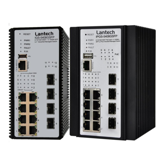
- Page 1 IPGS-3XXX IPGS-5XXX IGS-3XXX IGS-5XXX IP30-rated Series IP30-rated L2 Industrial Managed Switch w/Enhanced G.8032 Ring User Manual (Hardware) Jul. 2016...
- Page 2 Recommendation for Shielded network cables STP cables have additional shielding material that is used to reduce external interference. The shield also reduces the emission at any point in the path of the cable. Our recommendation is to deploy an STP network cable in demanding electrical environments. Examples of demanding indoor environments are where the network cable is located in parallel with electrical mains supply cables or where large inductive loads such as motors or contactors are in close vicinity to the camera or its cable.
- Page 3 Lantech Communications Global Inc. Products offered may contain software which is proprietary to Lantech Communications Global Inc. The offer or supply of these products and services does not include or infer any transfer of ownership.
- Page 4 FCC Warning This Equipment has been tested and found to comply with the limits for a Class-A digital device, pursuant to Part 15 of the FCC rules. These limits are designed to provide reasonable protection against harmful interference in a residential installation. This equipment generates, uses, and can radiate radio frequency energy.
-
Page 5: Table Of Contents
Content Chapter 1 Hardware Features ......... 1 Chapter 2 Hardware Description ......4 IP Protection ........... 4 LED Indicators..........7 Chapter 3 Hardware Installation ......9 3.1Hardware installation .......... 9 DIN-Rail Mounting ........10 Wall Mount Plate Mounting ......12 Wiring the Power Inputs ....... -
Page 6: Chapter 1 Hardware Features
Chapter 1 Hardware Features IEEE 802.3 10Base-T Ethernet IEEE 802.3u 100Base-TX IEEE802.3z Gigabit fiber IEEE802.3x Flow Control and Back Pressure IEEE802.3ad Port trunk with LACP IEEE802.1d Spanning Tree IEEE802.1w Rapid Spanning Tree Standard IEEE802.1s Multiple Spanning Tree IEEE 802.3ad Link Aggregation Control Protocol (LACP) IEEE 802.1AB Link Layer Discovery Protocol (LLDP) IEEE 802.1X User Authentication (Radius) IEEE802.1p Class of Service... - Page 7 10/100/1000T: 2-pair UTP/STP Cat. 5/ 5E / 6 cable Network Cable EIA/TIA-568 100-ohm (100m) Protocol CSMA/CD Per unit: Power 1 (Green), Power 2 (Green), P-Fail (Red) Ethernet port: Link/Activity (Green), Speed (Green); Giga-T: Link/Activity (Green) PoE FWD: Green( IPGS) 1 Digital Input(DI): Level 0: -30~2V/Level1: 10~30V DI/DO Max.
- Page 8 IEC60068-2-32 (Free fall), IEC60068-2-27 (Shock), Stability Testing IEC60068-2-6 (Vibration) *For detail specifications, please refer to product datasheet. **The revise authority rights of product specifications belong to Lantech Communications Global, Inc. Lantech may make changes to specification and product descriptions at anytime, without notice.
-
Page 9: Chapter 2 Hardware Description
Chapter 2 Hardware Description In this paragraph, it will describe the Industrial switch’s hardware spec, port, cabling information, and wiring installation. 2.1 IP Protection The IP Code, Ingress Protection Rating, sometimes also interpreted as International Protection Rating, classifies and rates the degree of protection provided against the intrusion (including body parts such as hands and fingers), dust, accidental contact, and water in mechanical casings and with electrical enclosures. - Page 10 protection against contact No ingress of dust; complete protection against Dust tight contact Liquid ingress protection The second digit indicates the level of protection that the enclosure provides against harmful ingress of water. Protected Level Testing for Details against — —...
- Page 11 Water jets Water projected by a Test duration: at least nozzle (6.3 mm) against 15 minutes enclosure from any Water volume: 12.5 litres per direction shall have no minute harmful effects. Pressure: 30 kPa at distance of 3 m Powerful Water projected in powerful Test duration: at least water jets...
-
Page 12: Led Indicators
it produces no harmful effects. — Powerful Protected against close- high range high pressure, high temperature temperature spray downs. water jets 2.2 LED Indicators The diagnostic LEDs that provide real-time information of system and optional status are located on the front panel of the industrial switch. The following table provides the description of the LED status and their meanings for the switch. - Page 13 (For PoE The port is operating in PoE mode. model) A network device is detected. The port is transmitting or receiving packets Blinking SFP Port from the TX device. No device attached.
-
Page 14: Chapter 3 Hardware Installation
Chapter 3 Hardware Installation 3.1Hardware installation 1. Unpack the Industrial switch 2. Check if the DIN-Rail is screwed on the Industrial switch or not. If the DIN-Rail is not screwed on the Industrial switch, please refer to DIN-Rail Mounting section for DIN- Rail installation. -
Page 15: Din-Rail Mounting
3.2 DIN-Rail Mounting The DIN-Rail is screwed on the industrial switch when out of factory. If the DIN-Rail is not screwed on the industrial switch, please see the following pictures to screw the DIN- Rail on the switch. Follow the steps below to hang the industrial switch. - Page 16 First, insert the top of DIN-Rail into the track. Then, lightly push the DIN-Rail into the track. Check if the DIN-Rail is tightened on the track or not. To remove the industrial switch from the track, reverse above steps.
-
Page 17: Wall Mount Plate Mounting
3.3 Wall Mount Plate Mounting Follow the steps below to mount the industrial switch with wall mount plate. 1. Remove the DIN-Rail from the industrial switch; loose the screws to remove the DIN- Rail. 2. Place the wall mount plate on the rear panel of the industrial switch. 3. -
Page 18: Wiring The Power Inputs
3.4 Wiring the Power Inputs Please follow the steps below to insert the power wire. 1. Insert AC or DC power wires into the contacts 1 and 2 for power 1, or 5 and 6 for power. 2. Tighten the wire-clamp screws for preventing the wires from loosing. [NOTE] The wire gauge for the terminal block should be in the range between 12 ~ 24 AWG. -
Page 19: Wiring The Fault Alarm Contact
3.5 Wiring the Fault Alarm Contact The fault alarm contacts are in the middle of the terminal block connector as the picture shows below. Inserting the wires, the switch will detect the fault status of the power failure, or port link failure (available for managed model) and then forms an open circuit. The following illustration shows an application example for wiring the fault alarm contacts. -
Page 20: Cabling
3.6 Cabling Use four twisted-pair, Category 5e or above cabling for RJ-45 port connection. The cable between the switch and the link partner (switch, hub, workstation, etc.) must be less than 100 meters (328 ft.) long. Fiber segment using single-mode connector type must use9/125 µm single-mode fiber cable. - Page 21 Transceiver Inserted Second, insert the fiber cable of LC connector into the transceiver. LC connector to the transceiver...
- Page 22 To remove the LC connector from the transceiver, please follow the steps shown below: First, press the upper side of the LC connector to release from the transceiver and pull it out. Remove LC connector Second, push down the metal loop and pull the transceiver out by the plastic handle. Pull out from the transceiver...
-
Page 23: Chapter 4 Network Application
Chapter 4 Network Application ITU G.8032 Scheme Lantech G.8032 protocol is following ITU (International Telecommunication Unit) G.8032 v2 draft. The benefits of G.8032 are: 1. <50ms recovery time when failover 2. G.8032 has defined the protocol scheme, parameters, functions, test measures to be unified that the users can evaluate the possible network infrastructure without literally testing each brand in large scale. -
Page 24: Multiple Rings
Multiple Rings... -
Page 25: Dual Homing
Dual Homing Chain... -
Page 27: Chapter 5 Console Management
Chapter 5 Console Management 5.1 Connecting to the Console Port The supplied cable which one end is RS-232 connector and the other end is RJ-45 connector. Attach the end of RS-232 connector to PC or terminal and the other end of RJ-45 connector to the console port of the switch. -
Page 28: Login In The Console Interface
5.2 Login in the Console Interface When the connection between Switch and PC is ready, turn on the PC and run a terminal emulation program or Hyper Terminal and configure its communication parameters to match the following default characteristics of the console port: Baud Rate:115200 bps Data Bits: 8 Parity: none... - Page 29 Console login interface ===============Notice=============== For web-based management, please refer to our “Software Management Manual” at http://www.lantechcom.tw/global/eng/support-downloads.html...
Need help?
Do you have a question about the IPGS-5 Series and is the answer not in the manual?
Questions and answers