
Related Manuals for Lantech IGS-0208GSFP


Summary of Contents for Lantech IGS-0208GSFP
- Page 1 Lantech I(P)GS-0208GSFP 8 10/100/1000T + 2 1G SFP (w/8 PoE at/af) Industrial Unmanaged Switch User Manual Aug 2021...
- Page 2 Recommendation for Shielded network cables STP cables have additional shielding material that is used to reduce external interference. The shield also reduces the emission at any point in the path of the cable. Our recommendation is to deploy an STP network cable in demanding electrical environments. Examples of demanding indoor environments are where the network cable is located in parallel with electrical mains supply cables or where large inductive loads such as motors or contactors are in close vicinity to the camera or its cable.
-
Page 3: Table Of Contents
Content Overview ............3 Introduction .............. 3 Packing List .............. 3 Safety Precaution ............. 3 Hardware Description ......... 4 Front Panel ............... 4 Top View ..............5 Dimensions .............. 5 Wiring the Power Inputs ........... 6 LED Indicators ............8 RJ-45 Pin Assignments .......... - Page 4 Troubleshooting ..........20...
-
Page 5: Overview
Overview Introduction Lantech I(P)GS-0208GSFP is a high performance all Gigabit switch with 8 10/100/1000T + 2x 1G SFP (w/8 PoE 802.3af/at Injectors.) For latest product specifications, please refer to Lantech official site. Packing List 1 x Industrial Ethernet Switch ... -
Page 6: Hardware Description
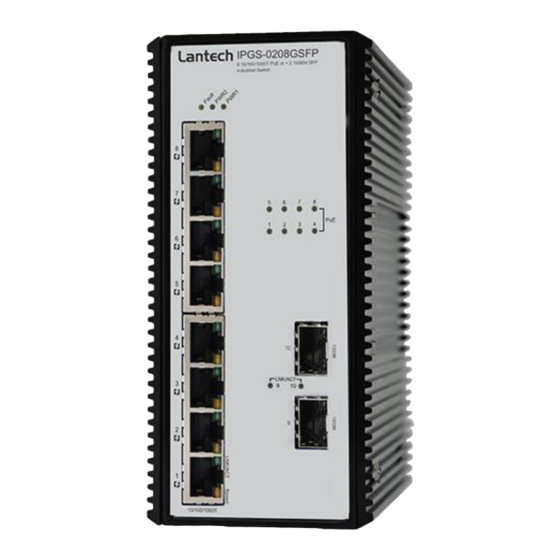
Hardware Description In this paragraph, we will introduce the Industrial switch’s dimensions, port, cabling information, and wiring installation. Front Panel The Front Panel of the switch is shown as below. Front Panel of the Industrial Switch... -
Page 7: Top View
Top View The top panel of the Industrial Switch is equipped one terminal block connector of two DC power inputs. Top panel of the Industrial Switch Converter Dimensions . The dimensions are 74 x 152 x 105 mm (W x H x D). The figure below gives the dimensions and views of each side of the Industrial Switch. -
Page 8: Wiring The Power Inputs
45V to 56VDC to feed power on both 802.3af/at standardized devices. The power input voltage can IGS-0208GSFP be from 9.5V to 60VDC Please make sure that the external power supply unit you use to provide the PoE voltage meet the following criteria: The power consumption can satisfy the total power request from all PD devices required. - Page 9 2. To tighten the wire-clamp screws for preventing the DC wires to loose. Note The wire gauge for the terminal block should be in the range between 12~ 24 AWG.
-
Page 10: Led Indicators
LED Indicators The LED indicators located on the front panel display the power status and network status of the Industrial switch; each has their own specific meaning as the table shown below. Color Description Power input 1 is active Green Power input 1 is inactive Power input 2 is active Green... -
Page 11: Rj-45 Pin Assignments
RJ-45 Pin Assignments The UTP/STP ports will automatically sense for Fast Ethernet (10Base-T/100Base-TX) or Gigabit Ethernet (10Base-T/100Base-TX/1000Base-T) connection. Auto MDI/MDIX means that the switch can connect to another switch or workstation without changing straight through or crossover cabling. See the figures below for straight through and crossover cable schema. - Page 12 10/100Base-TX Cable Schema Straight Through Cable Schema Crossover Cable Schema 10/100/1000Base-T Pinouts The table below describes the gigabit Ethernet RJ-45 pinouts. Signal name Description BI_DA+ Bi-directional pair A+ BI_DA- Bi-directional pair A- BI_DB+ Bi-directional pair B+ BI_DC+ Bi-directional pair C+ BI_DC- Bi-directional pair C- BI_DB-...
-
Page 13: Cabling
10/100/1000Base-T Cable Schema The following two figures illustrate the 10/100/1000Base-T cable schema. Straight Through Cable Schema Crossover Cable Schema Cabling Use unshielded twisted-pair (UTP) or shielded twisted-pair (STP) cable for RJ-45 connections: 100Ω Category 3, 4 or 5 cable for 10Mbps connections, 100Ω... - Page 14 up to 30km. Fiber segment using multi-mode connector type must use 50 or 62.5/125 µm multi-mode fiber cable. User can connect two devices up to 2kmdistances. Gigabit SFP port: The small form-factor pluggable (SFP) is a compact optical transceiver used in optical communications for both telecommunication and data communications.
- Page 15 Transceiver Inserted Second, insert the fiber cable of LC connector into the transceiver. LC connector to the transceiver...
- Page 16 To remove the LC connector from the transceiver, please follow the steps shown below: First, press the upper side of the LC connector to release from the transceiver and pull it out. Remove LC connector Second, push down the metal loop and pull the transceiver out by the plastic handle.
-
Page 17: Mounting Installation
Mounting Installation DIN-Rail Mounting The DIN-Rail is screwed on the industrial switch when out of factory. If the DIN-Rail is not screwed on the industrial switch, please see the following pictures to screw the DIN-Rail on the switch. Follow the steps below to hang the industrial switch. - Page 18 First, insert the top of DIN-Rail into the track. Then, lightly push the DIN-Rail into the track. Check if the DIN-Rail is tightened on the track or not. To remove the industrial switch from the track, reverse above steps.
-
Page 19: Wall-Mount Plate Mounting
Wall-Mount Plate Mounting *Optional Wall Mount Kit required Follow the steps below to mount the industrial switch with wall mount plate. 1. Remove the DIN-Rail from the industrial switch; loose the screws to remove the DIN-Rail. 2. Place the wall mount plate on the rear panel of the industrial switch. 3. -
Page 20: Hardware Installation
Hardware Installation In this paragraph, we will describe how to install the 8-port 10/100/1000Base-TX Industrial Switch and the installation points for the attention. -
Page 21: Installation Steps
Installation Steps Unpacked the Industrial switch. Check the DIN-Rail is screwed on the Industrial switch. If the DIN-Rail is not screwed on the Industrial switch. Please refer to DIN-Rail Mounting section for DIN-Rail installation. If you want to wall mount the Industrial switch, then please refer to Wall-Mount Plate Mounting section for wall mount plate installation. - Page 22 Troubleshooting Verify that you are using the included or appropriate power cord/adapter. Don’t use the power adapter with DC output higher than the power rating of the device. Otherwise, the device will burn down. Select the proper UTP/STP cable to construct your network. Please check that you are using the right cable.
Need help?
Do you have a question about the IGS-0208GSFP and is the answer not in the manual?
Questions and answers