
Related Manuals for Lantech IPGS-5008T Series


Summary of Contents for Lantech IPGS-5008T Series
- Page 1 IPGS/IGS-5008T-X Series 8 10/100/1000T X-coded L2 (w/8 PoE at/af) Industrial Managed Switch w/Enhanced G.8032 Ring User Manual (Hardware) IP-67 IP-54 Sept. 2017...
- Page 2 Recommendation for Shielded network cables STP cables have additional shielding material that is used to reduce external interference. The shield also reduces the emission at any point in the path of the cable. Our recommendation is to deploy an STP network cable in demanding electrical environments. Examples of demanding indoor environments are where the network cable is located in parallel with electrical mains supply cables or where large inductive loads such as motors or contactors are in close vicinity to the camera or its cable.
- Page 3 Lantech Communications Global Inc. Products offered may contain software which is proprietary to Lantech Communications Global Inc. The offer or supply of these products and services does not include or infer any transfer of ownership.
- Page 4 FCC Warning This Equipment has been tested and found to comply with the limits for a Class-A digital device, pursuant to Part 15 of the FCC rules. These limits are designed to provide reasonable protection against harmful interference in a residential installation. This equipment generates, uses, and can radiate radio frequency energy.
-
Page 5: Table Of Contents
Content Chapter 1 Introduction ..........5 Specification ............. 5 Chapter 2 Hardware Description ......10 Physical Dimension ........10 Package Content:......... 12 IP Protection ..........12 LED Indicators..........15 Chapter 3 Hardware Installation ......17 Chapter 4 Network Application ......21 4.1 ITU G.8032 Scheme ........ -
Page 6: Chapter 1 Introduction
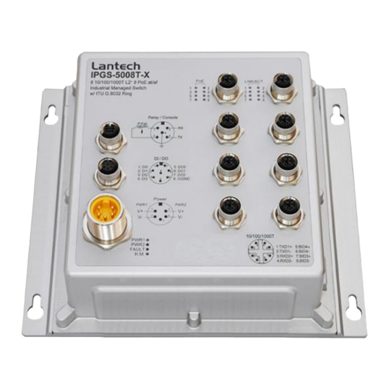
Chapter 1 Introduction Lantech IPGS-5008T-X (IP67/IP54) is a high performance L2+ All Gigabit switch with 8 10/100/1000T w/8 PoE at/af injectors at M12 X-coded providing L2 wire speed and advanced security function for network aggregation deployment. It houses in a IP67/IP54 aluminum compact enclosure that is waterproof and will prevent moisture ingress due to temperature fluctuations. - Page 7 Jumbo frame 10KB on all ports Connectors 10/100/1000T: 8 x ports M12 8-pole X-coded with Auto MDI/MDI-X function RS-232 connector: 1 x M12 5-pole A-coded Power Input connector : 1 x M12 5-pole A-coded Relay contact : 1 x M12 5-pole A-coded Network Cable 10Base-T: 2-pair UTP/STP Cat.
- Page 8 IP54 model: Aluminum case 194mm(W)x165mm(H)x82mm(D) Weight 1.4kgs(IP67); 980gs (IP54) Installation DIN Rail** and Wall Mount Design EMI & EMS FCC Class A, CE EN61000-6-2, CE EN61000-6-4, CE EN61000-4-2, CE EN61000-4-3, CE EN61000-4-4, CE EN61000-4-5, CE EN61000-4-6, CE N61000-4-8, EN61000-4-11 Stability Testing IEC60068-2-32 (Free fall), EN61373 (Shock and Vibration) Certifications&...
- Page 9 Architecture Packet throughput ability (Full-Duplex): 23.8Mpps @64bytes Transfer Rate 14,880pps for Ethernet port 148,800pps for Fast Ethernet port 1,488,000pps for Gigabit Ethernet port Marvell 800Mhz 256M Byte Flash 128M Byte Mac Address 16K MAC address table Jumbo frame 10KB on all ports Connectors 10/100/1000T: 8 x ports M12 8-pole X-coded with Auto MDI/MDI-X function...
- Page 10 Storage -40°C~85°C / -40°F~185°F Temperature Power Supply 24V model: 9.5~56VDC WV model: 9.5~137.5VDC Power Max. 25W Consumption PoE Budget PoE pin M12 port # 1~#8 support IEEE 802.3at/af End-point, assignment Alternative A mode. Per port provides 15W class 0-4. Case Dimension IP67 model: Aluminum case 215mm(W)x200mm(H)x84.4mm(D) IP54 model: Aluminum case...
-
Page 11: Chapter 2 Hardware Description
Chapter 2 Hardware Description In this paragraph, it will describe the Industrial switch’s hardware spec, port, cabling information, and wiring installation. 2.1 Physical Dimension Aluminum case. IP-67, 215 (W) x 200 (D) x 84.4 (H) mm... - Page 12 Port description of IP-67 series switch Aluminum case. IP-54, 194 (W) x 165 (D) x 82 (H) mm **The port description of IP-54 model is the same as of IP-67 one.
-
Page 13: Package Content
2.2 Package Content: Manual CD Product Console cable 2.3 IP Protection The IP Code, Ingress Protection Rating, sometimes also interpreted as International Protection Rating, classifies and rates the degree of protection provided against the intrusion (including body parts such as hands and fingers), dust, accidental contact, and water in mechanical casings and with electrical enclosures. - Page 14 Any large surface of the body, such as the back of a >50 mm hand, but no protection against deliberate contact with a body part >12.5 mm Fingers or similar objects >2.5 mm Tools, thick wires, etc. >1 mm Most wires, screws, etc. Ingress of dust is not entirely prevented, but it must not enter in sufficient quantity to interfere with the Dust protected...
- Page 15 Spraying Water falling as a spray at Test duration: 5 minutes water any angle up to 60° from Water volume: 0.7 litres per the vertical shall have no minute harmful effect. Pressure: 80–100 kPa Splashing Water splashing against Test duration: 5 minutes of water the enclosure from any Water volume: 10 litres per...
-
Page 16: Led Indicators
the manufacturer. Normally, this will mean that the equipment is hermetically sealed. However, with certain types of equipment, it can mean that water can enter but only in such a manner that it produces no harmful effects. — Powerful Protected against close- high range high pressure, high temperature... - Page 17 No failure A network device is detected. The port is transmitting or receiving packets Link/Ack Blinking from the TX device. P1 ~ P8 No device attached The port is operating in PoE mode.(IPES) PoE(1~8)(IP The port is not operating in PoE mode.(IPES)
-
Page 18: Chapter 3 Hardware Installation
Chapter 3 Hardware Installation 3.1Hardware installation 3.1.1Unpack switch and check the accessory with packing content list 3.1.2 Mount the switch on desired position. For the best ventilation, it is suggested to mount the switch on metallic surface. 3.1.3 Connect the M23/M12 connector of power input. ... - Page 19 PD devices required. Non-PoE model (M12) PoE model (M23) Pin assignment of Power input Dual Power Input The power input can be supported redundantly. The supply voltage is electrically isolated from the housing. Note: With single power supply of the mains voltage, the device will report a power failure.
- Page 20 3.1.4 Fitting the device, grounding Install the system in a dry and clean area to protect the switch to get exposed with dirt. Plug the connector to the power supply plug then turn on the power supply. Ground The chassis is grounded via a separate ground nut (M3). Use toothed locking washers for a good electrical connection.
- Page 21 Pin assignment of M12 10/100/1000T network connector 3.1.6 Check the status of LED, make sure the switch was in working status. Note: The protection class IP67/IP54 is only achieved when bolted together. The other components attaching to the system have to meet with the IP67/IP54 protection class in order to reach the whole system IP 67/IP54 protection.
-
Page 22: Chapter 4 Network Application
Chapter 4 Network Application 4.1 ITU G.8032 Scheme LANTECH G.8032 protocol is following ITU (International Telecommunication Unit) G.8032 v2 draft. The benefits of G.8032 are: 1. <50ms recovery time when failover 2. G.8032 has defined the protocol scheme, parameters, functions, test measures to be unified that the users can evaluate the possible network infrastructure without literally testing each brand in large scale. -
Page 23: Multiple Rings
4.3 Multiple Rings... -
Page 24: Dual Homing
4.4 Dual Homing 4.5 Chain... -
Page 26: Chapter 5 Console Management
Chapter 5 Console Management 5.1 Connecting to the Console Port The supplied cable which one end is M12 5-pole connector and the other end is RS-232 connector. Attach the end of RS-232 connector to PC or terminal and the other end of M12 connector to the console port of the switch. - Page 27 The settings of communication parameters Having finished the parameter settings, click ‘OK’. When the blank screen shows up, press Enter key to have the login prompt appears. Key in ‘admin’ (default value) for both User name and Password (use Enter key to switch), then press Enter and the Main Menu of console management appears.
Need help?
Do you have a question about the IPGS-5008T Series and is the answer not in the manual?
Questions and answers