Table of Contents
Advertisement
Quick Links
Copyright
This publication, including all photographs, illustrations and software,
is protected under international copyright laws, with all rights re-
served. Neither this manual, nor any of the material contained herein,
may be reproduced without written consent of the author.
Version 1.0
Disclaimer
The information in this document is subject to change without notice.
The manufacturer makes no representations or warranties with re-
spect to the contents hereof and specifically disclaims any implied
warranties of merchantability or fitness for any particular purpose.
The manufacturer reserves the right to revise this publication and to
make changes from time to time in the content hereof without obliga-
tion of the manufacturer to notify any person of such revision or
changes.
Trademark Recognition
Microsoft, MS-DOS and Windows are registered trademarks of Mi-
crosoft Corp.
MMX, Pentium, Pentium-II, Pentium-III, P4/Northwood, Celeron are
registered trademarks of Intel Corporation.
Other product names used in this manual are the properties of their
respective owners and are acknowledged.
Preface
Advertisement
Table of Contents

Subscribe to Our Youtube Channel
Related Manuals for ECS P4IBAS2


Summary of Contents for ECS P4IBAS2
- Page 1 Preface Copyright This publication, including all photographs, illustrations and software, is protected under international copyright laws, with all rights re- served. Neither this manual, nor any of the material contained herein, may be reproduced without written consent of the author. Version 1.0 Disclaimer The information in this document is subject to change without notice.
- Page 2 Federal Communications Commission (FCC) This equipment has been tested and found to comply with the limits for a Class B digital device, pursuant to Part 15 of the FCC Rules. These limits are designed to provide reasonable protection against harmful interference in a residential installation. This equipment gen- erates, uses, and can radiate radio frequency energy and, if not installed and used in accordance with the instructions, may cause harmful interference to radio communications.
- Page 3 Declaration of Conformity This device complies with part 15 of the FCC rules. Operation is sub- ject to the following conditions: − This device may not cause harmful interference, and − This device must accept any interference received, includ- ing interference that may cause undesired operation. Canadian Department of Communications This class B digital apparatus meets all requirements of the Cana- dian Interference-causing Equipment Regulations.
- Page 4 About the Manual The manual consists of the following: Chapter 1 Describes features of the main- board, and provides a shipping Introducing the Mainboard checklist. ⇒ Go to page 1 Chapter 2 Describes installation of main- board components. Installing the Mainboard ⇒...
-
Page 5: Table Of Contents
Preface CHAPTER 1 Introducing the Mainboard Introduction ................1 Checklist................... 1 Standard Items ....................1 Features ................... 2 Mainboard Components ............. 4 Choosing a Computer Case ............7 CHAPTER 2 Installing the Mainboard Safety Precautions ..............8 Quick Guide ................9 Checking Jumper Settings ............ - Page 6 Standard CMOS Features ................41 Advanced BIOS Setup Option..............44 Advanced Chipset Features Option............47 Integrated Peripherals Option ..............50 Power Management Setup Option............. 54 PNP/PCI Configuration Option ..............59 PCI Health Status Option................61 Frequency/Voltage Control................. 62 Load Fail-Safe Defaults Option..............64 Load Optimized Defaults Option ..............
-
Page 7: Introducing The Mainboard
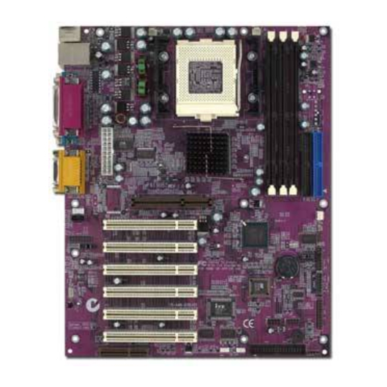
Introducing the Mainboard Congratulations on purchasing the P4IBAS2 mainboard. The P4IBAS2 mainboard is an ATX mainboard that uses a 4-layer printed circuit board and measures 305 mm x 244 mm. The mainboard features a Socket 423 that accommodates Intel Pentium 4 processors supporting system bus (FSB) speeds up to 400 MHz and data bus bandwidths up to 3.2 GB/s... -
Page 8: Features
The mainboard can accommodate 3.3V, un- buffered, 168 pin DIMM DRAM with a total capacity of 3 GB. The P4IBAS2 includes a 4xAGP slot that provides four times the bandwidth of the original AGP specifi- cation. AGP technology provides a direct connection... - Page 9 • One Onboard LAN chip and LAN port on top of the USB port (optional) The P4IBAS2 supports Ultra DMA bus mastering with transfer rates of 33/66/100 MB/sec. Integrated I/O The mainboard has a full set of I/O ports and con- nectors: •...
- Page 11 Table of Mainboard Components Label Component AGP1 Accelerated Graphics Port ATX1 Standard 20-pin ATX power connector ATX2 Aux Vcc and Vcc3 6-pin ATX power connector ATX3 +12 VDC 2 x 2 ATX power connector AUDIO1 Microphone and speaker-out header BAT1 Three volt realtime clock battery CASFAN1 Case Fan...
- Page 12 WOL1 Wake On LAN wakeup connector WOR1 Wake On Ring wakeup connector Note: LED1 – This red indicator warns you that the com- puter is still powered on and you should not install or uninstall memory modules.
-
Page 13: Choosing A Computer Case
There are many types of computer cases on the market. The mainboard complies with the specifications for the ATX sys- tem case. Some features on the mainboard are implemented by cabling connectors on the mainboard to indicators and switches on the system case. Ensure that your case supports all the features required. -
Page 14: Installing The Mainboard
Installing the Mainboard Follow these safety precautions when installing the mainboard: • Wear a grounding strap attached to a grounded device to avoid damage from static electricity. • Discharge static electricity by touching the metal case of a safely grounded object before working on the mainboard. -
Page 15: Quick Guide
This Quick Guide suggests the steps you can take to assem- ble your system with the mainboard. The following table provides a reference for installing specific components: Locating Mainboard Components Go to page 4 Setting Jumpers Go to page 10 Installing the Mainboard in a Case Go to page 13 Installing Case Components... -
Page 16: Checking Jumper Settings
This section explains how to set jumpers for correct configura- tion of the mainboard. Setting Jumpers Use the mainboard jumpers to set system configuration op- tions. Jumpers with more than one pin are numbered. When setting the jumpers, ensure that the jumper caps are placed on the correct pins. -
Page 17: Checking Jumper Settings
Checking Jumper Settings The following illustration shows the location of the mainboard jumpers. Pin 1 is labeled. Jumper Settings Jumper Type Description Setting (default) 3-pin Clear CMOS 1-2: Normal 2-3: Clear 2-pin BIOS Protect Open: Disable Short: Enable... - Page 18 JP1 – Enables you to clear the BIOS. Refer to the following instruc- tions: 1. Turn the system off. 2. Remove all ATX power connectors. 3. Short pins 2 and 3 on JP1. 4. Return the jumper to the normal setting. 5.
-
Page 19: Installing The Mainboard In A Case
Refer to the following illustration and instructions for installing the mainboard in a case: 2. Secure the mainboard with This illustration shows screws where appropriate. an example of a main- board being installed in a tower-type case: Note: Do not over- tighten the screws as this can stress the... -
Page 20: Connecting Case Components
After you have installed the mainboard into a case, you can begin connecting the mainboard components. 1. Supply power to the mainboard using the three ATX connectors. • Connect the 20-pin power supply connector to ATX1 (connection is required). Note: When the system is heavily loaded, you should install, at a minimum, an ATX power supply with a 300W capacity. -
Page 21: The Panel1 And Lpanel1 Connectors
4. Connect the auxiliary power supply cooling fan con- nector to PWRFAN1. 5. See below for PANEL1 and LPANEL 1 pin descriptions. The PANEL1 and LPANEL1 Connectors The panel connector provides a set of switch and LED con- nectors commonly found on ATX or Micro ATX cases. Select one from the two types of panel connector supported by this mainboard. - Page 22 LPANEL1 Device Pins Reset 13, 14 Empty Switch (Pin 7) Reset Switch (Pins 13, 14) Case 9 ~ 12 Speaker Power Switch (Pin 5, 6) Power 5, 6 Switch Power LED Power LED (Pin 4) Case Speaker Green (Pins 9 ~ 12) Green Power LED Power LED (Pin 3)
-
Page 23: Installing Hardware
Installing the Processor Caution: When installing a CPU heatsink and cooling fan make sure that you DO NOT scratch the mainboard or any of the surface-mount resistors with the clip of the cooling fan. If the clip of the cooling fan scrapes across the main- board, you may cause serious damage to both the mainboard or its components. - Page 24 This mainboard has a Socket 423 processor socket. When choosing a processor, consider the performance requirements of the system. Performance is based on the processor design, the clock speed and system bus frequency of the processor, and the quantity of internal cache memory and external cache memory.
- Page 25 4. Swing the locking lever down and hook it under the latch on the edge of the socket. 5. Apply thermal grease to the top of the CPU. 6. Insert the CPU cooling fan/heatsink assembly. 7. Plug the CPU fan cable connector into the CPU cool- ing fan power supply on the mainboard (CFAN1).
- Page 26 8. Insert the retention module clips over the edge of the CPU fan/heatsink assembly: Note: After you have assembled the system, you must set the correct clock speed and frontside bus (FSB) speed. Check the jumper section in Appendix A and refer to Chapter 3 “Frequency Voltage Control”...
-
Page 27: Installing Memory Modules
Installing Memory Modules For this mainboard, you must use 168-pin 3.3V non-buffered Dual In-line Memory Modules (DIMMs). The memory chips are standard SDRAM (Synchronous Dynamic Random Access Memory). The table below shows the supported frequencies. Frontside Bus System Memory (FSB) Bus (SMB) Frequency Frequency... - Page 28 Check that the cutouts on the DIMM module edge connector match the notches in the DIMM slot: Latch Cutouts Notches Latch 2. Push the latches on each side of the DIMM slot down. 3. Install the DIMM module into the slot and press it firmly down so that it seats correctly.
-
Page 29: Installing A Hard Disk Drive/Cd-Rom
Installing a Hard Disk Drive/CD-ROM This section describes how to install IDE devices such as a hard disk drive and a CD-ROM drive. About IDE Devices Your mainboard has a primary and secondary IDE channel inter- face (IDE1 and IDE2). An IDE ribbon cable supporting two IDE devices is bundled with the mainboard. - Page 30 Installing a Hard Disk Drive 1. Install the hard disk drive into the drive cage in your Micro ATX system case. 2. Plug the IDE cable into IDE1 (A): Note: The ribbon cable connectors are keyed so that they can only be installed correctly on the device connec- tor.
- Page 31 Installing a CD-ROM/DVD Drive 1. Install the CD-ROM/DVD drive into the drive cage in your Micro ATX system case. 2. Plug the IDE cable into IDE1 (A). If you have already installed an HDD, use the other connector on the IDE cable.
-
Page 32: Installing A Floppy Diskette Drive
When you first start up your system, the BIOS should auto- matically detect your CD-ROM/DVD drive. If it doesn’t, enter the Setup Utility and configure the CD-ROM/DVD drive that you have installed. See IDE Primary/Secondary Master/Slave (Auto)on page 43 for more information. Installing a Floppy Diskette Drive The mainboard has a floppy diskette drive (FDD) interface and ships with a diskette drive ribbon cable that supports one... -
Page 33: Installing Add-On Cards
Note: The ribbon cable connectors are keyed so that they can only be installed correctly on the device connec- tor. If the connector is not keyed, make sure that you match the pin-1 side of the cable connector with the pin-1 side of the device connector. - Page 34 Note: Before installing an add-on card, check the docu- mentation for the card carefully. If the card is not Plug and Play, you may have to manually configure the card before installation. 1. Remove a blanking plate from the system case corre- sponding to the slot you are going to use.
-
Page 35: Connecting Optional Devices
Connecting Optional Devices Refer to the following for information on connecting the main- board’s optional devices: AUDIO1: Front panel audio header This mainboard supports front panel microphone and speaker out ports. If your computer case has these ports, connect them to AUDIO1. Signal Name Signal Name MICIN... - Page 36 WOL1/WOR1: Wake On LAN/Wake On Modem If you have installed a LAN card, use the cable provided with the card to plug into the mainboard WOL1 connector. This en- ables the Wake On LAN (WOL) feature. When your system is in a power-saving mode, any LAN signal automatically r e- sumes the system.
- Page 37 USB2: On board USB port The mainboard has USB ports installed on the rear edge I/O port array (see page 34). However, some computer cases have a special module that mounts USB ports at the front of the case. If you have this kind of case, use auxiliary USB connector USB1 to connect the front-mounted ports to the mainboard.
- Page 38 J2: Smart I/O This connector is for use with media storage devices using the LPC interface. Signal Name Signal Name PCICLK VCC3 SERIRQ VCC3 LFRAME# LDRQ# LAD0 5VSB LAD1 LAD2 LAD3 RESERVED(GND) PCIRST# VCC5 PME# VCC5 LAUDIO1: Front Panel Audio header 2 This panel connector which is specially designed for OEM customers provides a set of front panel microphone &...
- Page 39 LUSB1: USB panel connector 2 This USB panel connector which is specially designed for OEM customers connects to the front panel or case USB ports that comply with the OEM specifications. Signal Name Signal Name USBPWR Ground USBPP2- Ground USBPP2+ USBPP3+ Ground USBPP3-...
-
Page 40: Connecting I/O Devices
The backplane of the mainboard has the following I/O ports: Parallel port (LPT1) Game port PS/2 port mouse PS/2 Serial port Serial port Microphone keyboard ports COM 1 COM 2 Line-in Line-out PS/2 Mouse Use the upper PS/2 port to connect a PS/2 pointing device. -
Page 41: External Connector Color Coding
External Connector Color Coding Many connectors now use standard colors as shown in the table below. Connector Color Analog VGA Blue Audio line-in Light blue Audio line-out Lime Digital monitor/flat panel White IEEE 1394 Grey Microphone Pink MIDI/game Gold Parallel Burgundy PS/2-compatible keyboard Purple... -
Page 42: Using Bios
Using BIOS The computer uses the latest Award BIOS with support for Windows Plug and Play. The CMOS chip on the mainboard contains the ROM setup instructions for configuring the main- board BIOS. The BIOS (Basic Input and Output System) Setup Utility dis- plays the system's configuration status and provides you with options to set system parameters. -
Page 43: The Standard Configuration
The Standard Configuration A standard configuration has already been set in the Setup Utility. However, we recommend that you read this chapter in case you need to make any changes in the future. This Setup Utility should be used: • when changing the system configuration •... -
Page 44: Entering The Setup Utility
Entering the Setup Utility When you power on the system, BIOS enters the Power-On Self Test (POST) routines. POST is a series of built-in diag- nostics performed by the BIOS. After the POST routines are completed, the following message appears: Press DEL to enter SETUP Pressing the delete key accesses the Award BIOS Setup... -
Page 45: Updating The Bios
Updating the BIOS You can download and install updated BIOS for this main- board from the manufacturer's Web site. New BIOS provides support for new peripherals, improvements in performance, or fixes for known bugs. Award Flash Memory Utility This utility lets you erase the system BIOS stored on a Flash Memory chip on the mainboard, and lets you copy an updated version of the BIOS to the chip. - Page 46 Install new BIOS as follows: 1. If your mainboard has a BIOS protection jumper, change the setting to allow BIOS flashing. (Refer to Appendix A for jumper settings.) 2. If your mainboard has an item called Firmware Write Pro- tect in Advanced BIOS features, disable it. (Firmware Write Protect prevents BIOS from being overwritten.) 3.
-
Page 47: Using Bios
When you start the Setup Utility, the main menu appears. The main menu of the Setup Utility displays a list of the options that are available. A highlight indicates which option is cur- rently selected. Use the cursor arrow keys to move the highlight to other options. - Page 48 Date and Time The Date and Time items show the current date and time on the computer. If you are running a Windows OS, these items are automatically updated whenever you make changes to the Windows Date and Time Properties utility. IDE Devices (None) Your computer has two IDE channels (Primary and Secondary) and each channel can be installed with one or two devices...
- Page 49 IDE Primary/Secondary Master/Slave (Auto) Leave this item at Auto to enable the system to automatically de- tect and configure IDE devices on the channel. If it fails to find a device, change the value to Manual and then manually configure the drive by entering the characteristics of the drive in the items described below.
-
Page 50: Advanced Bios Setup Option
Video (EGA/VGA) This item defines the video mode of the system. This main- board has a built-in VGA graphics system; you must leave this item at the default value. Halt On (All Errors) This item defines the operation of the system POST (Power On Self Test) routine. - Page 51 Anti-virus Protection (Disabled) When enabled, this item provides protection against viruses that try to write to the boot sector and partition table of your hard disk drive. You need to disable this item when installing an operating system. We recommend that you enable this item as soon as you have installed an operating system.
- Page 52 Boot Up Floppy Seek (Enabled) If this item is enabled, it checks the size of the floppy disk drives at start-up time. You don't need to enable this item un- less you have a legacy diskette drive with 360K capacity. Boot Up NumLock Status (On) This item defines if the keyboard Num Lock key is active when your system is started.
-
Page 53: Advanced Chipset Features Option
OS Select For DRAM > 64 MB (Non-OS2) This item is only required if you have installed more than 64 MB of memory and you are running the OS/2 operating sys- tem. Otherwise, leave this item at the default. HDD S.M.A.R.T Capability (Disabled) The S.M.A.R.T. - Page 54 DRAM Timing Selectable (By Manual) The value in this field depends on performance parameters of the installed memory chips (DRAM). Do not change the value from the factory setting unless you install new memory that has a different performance rating than the original DRAMs. CAS Latency Time: (3) When synchronous DRAM is installed, the number of clock c y- cles of CAS latency depends on the DRAM timing.
- Page 55 System BIOS Cacheable (Disabled) This item allows the system to be cached in memory for faster execution. Enable this item for better performance. Video RAM Cacheable (Disabled) These items allow the video BIOS and RAM to be cached in memory for faster execution. Enable these items for better performance.
-
Page 56: Integrated Peripherals Option
Integrated Peripherals Option These items define the operation of peripheral components on the system's input/output ports. CMOS Setup Utility – Copyright (C) 1984 – 2001 Award Software Integrated Peripherals Item Help On-Chip Primary PCI IDE [Enabled ] IDE Primary Master PIO [Auto] Menu Level IDE Primary Slave... - Page 57 USB Controller (Enabled) Enable this item if you plan to use the Universal Serial Bus ports on this mainboard. USB Keyboard Support (Disabled) Enable this item if you plan to use a keyboard connected through the USB port in a legacy operating system (such as DOS) that does not support Plug and Play.
- Page 58 POWER ON Function (Hot KEY) Enables you to set power on parameters. The default setting enables you to use a hot key to turn on the system. KB Power ON Password (Enter) When the POWER ON Function is set to Password, use this item to set the password.
- Page 59 UR2 Duplex Mode (Half) This field is available when UART 2 Mode is set to either ASKIR or IrDA. This item enables you to determine the infra- red function of the onboard infrared chip. The options are Full and Half (default). Full-duplex means that you can transmit and send information simultaneously.
-
Page 60: Power Management Setup Option
Power Management Setup Option This option lets you control system power management. The system has various power-saving modes including powering down the hard disk, turning off the video, suspending to RAM, and software power down that allows the system to be auto- matically resumed by certain events. - Page 61 ACPI Function (Enabled) This mainboard supports ACPI (Advanced Configuration and Power management Interface). Use this item to enable or dis- able the ACPI feature. Note: ACPI is a power management specification that makes hardware status information available to the operating system. ACPI enables a PC to turn its pe- ripherals on and off for improved power management.
- Page 62 Video Off In Suspend (Yes) This option defines if the video is powered down when the system is put into suspend mode. Suspend Type (Stop Grant) If this item is set to the default Stop Grant, the CPU will go into Idle Mode during power saving mode.
- Page 63 Wake-Up by PCI Card (Enable) When this item is enabled, the system power will be turned on if there is any PCI card activity. Power On by Ring (Enable) If this item is enabled, it allows the system to resume from a software power down or a power-saving mode whenever there is an incoming call to an installed fax/modem.
- Page 64 Primary/Secondary IDE 1/0 (Disabled) When these items are enabled, the system will restart the power-saving timeout counters when any activity is detected on any of the drives or devices on the primary or secondary IDE channels. FDD, COM, LPT Port (Disabled) When this item is enabled, the system will restart the power- saving timeout counters when any activity is detected on the floppy disk drive, serial ports, or the parallel port.
-
Page 65: Pnp/Pci Configuration Option
PNP/PCI Configuration Option This option configures how PnP (Plug and Play) and PCI ex- pansion cards operate in your system. Both the ISA and PCI buses on the Mainboard use system IRQs (Interrupt Re- Quests) and DMAs (Direct Memory Access). You must set up the IRQ and DMA assignments correctly through the PnP/PCI Configurations Setup utility for the mainboard to work properly. - Page 66 Resources Controlled By (Auto(ESCD)) You should leave this item at the default Auto(ESCD). Under this setting, the system dynamically allocates resources to Plug and Play devices as they are required. If you cannot get a legacy ISA (Industry Standard Architecture) expansion card to work properly, you might be able to solve the problem by changing this item to Manual, and then open- ing up the IRQ Resources and Memory Resources submenus.
-
Page 67: Pci Health Status Option
PCI Health Status Option On mainboards that support hardware monitoring, this item lets you monitor the parameters for critical voltages, critical temperatures, and fan speeds. CMOS Setup Utility – Copyright (C) 1984 – 2001 Award Software PC Health Status Item Help Shutdown Temperature [70°C/158°F] CPU Vcore... -
Page 68: Frequency/Voltage Control
Frequency/Voltage Control This item enables you to set the clock speed and system bus for your system. The clock speed and system bus are deter- mined by the kind of processor you have installed in your system. CMOS Setup Utility – Copyright (C) 1984 – 2001 Award Software Frequency/Voltage Control Item Help CPU Voltage... - Page 69 CPU Host/3V66/PCI Clock (Default) Use the CPU Host Clock to set the frontside bus frequency for the installed processor (usually 133 MHz, 100 MHz or 66 MHz).
-
Page 70: Load Fail-Safe Defaults Option
Load Fail-Safe Defaults Option This option opens a dialog box that lets you install fail-safe de- faults for all appropriate items in the Setup Utility: Press <Y> and then <Enter> to install the defaults. Press <N> and then <Enter> to not install the defaults. The fail-safe de- faults place no great demands on the system and are generally stable. -
Page 71: Save & Exit Setup Option
4. Press <Enter> after you have typed in the password. If you are deleting a password that is already installed, press <Enter> when the password dialog box appears. You see a message that indicates that the password has been disabled. PASSWORD DISABLED !!! Press any key to continue . -
Page 72: Using The Mainboard Software
Using the Mainboard Software The support software CD-ROM that is included in the main- board package contains all the drivers and utility programs needed to properly run the bundled products. Below you can find a brief description of each software program, and the lo- cation for your mainboard version. -
Page 73: Auto-Installing Under Windows 98
The Auto-install CD-ROM makes it easy for you to install the drivers and software for your mainboard. Note: If the Auto-install CD-ROM does not work on your system, you can still install drivers through the file manager for your OS (for example, Windows Ex- plorer). -
Page 74: Running Setup
Browse CD The Browse CD button is the standard Windows command that allows you to open Windows Explorer and show the con- tents of the support CD. Before installing the software from Windows Explorer, look for a file named README.TXT, INSTALL.TXT or something simi- lar. - Page 75 Note: The following screens are examples only. The screens and driver lists will be different according to the mainboard you are installing. The mainboard identification is located in the upper left-hand corner. 2. Click Next. The following screen appears: 3. Check the box next to the items you want to install. The default options are recommended.
-
Page 76: Drivers Installation
Audio Drivers and Software Most of the sub-folders in this folder are empty, with a short README file giving directions to alternate folders for the ap- propriate software. Installation for Windows 2000/98/98SE/ME/95 To install the audio drivers, go the directory \INTEL\ REALTEK- CODEC\;... - Page 77 LAN Software (optional) The enhanced LAN drivers for this mainboard are in the \PERIPHERAL\LAN\Realtek folder. Drivers are supplied for Windows 2000/98/95/NT. Installation for Windows 2000/98/98SE/ME/95/NT Go to the \PERIPHERAL\LAN\Realtek folder and run RSET8139.EXE to install the LAN driver for your operating system.
-
Page 78: Utility Software Reference
All the utility software available from this page is Windows compliant. They are provided only for the convenience of the users. The following software is furnished under l i cense and may only be used or copied in accordance with the terms of the license. - Page 79 CD Ghost The CD Ghost software enables you to create a virtual cabinet of CD-ROM drives on your system to help you categorize and organize your CD collection. A user-friendly interface assists you in quickly creating images of both CDs and DVDs onto your system.
-
Page 80: Setting Jumpers
Setting Jumpers Jumper Settings Jumper Type Description Setting (default) 3-pin Clear CMOS 1-2: Normal 2-3: Clear 2-pin BIOS Protect Open: Disable Short: Enable JP1 – Enables you to clear the BIOS. Refer to the following instruc- tions: 1. Turn the system off. 2. -
Page 81: The Panel1 And Lpanel1 Connectors
The PANEL1 and LPANEL1 Connectors The panel connector provides a set of switch and LED con- nectors commonly found on ATX or Micro ATX cases. Select one from the two types of panel connector supported by this mainboard. PANEL1 Device Pins Empty HDD LED...
Need help?
Do you have a question about the P4IBAS2 and is the answer not in the manual?
Questions and answers