Table of Contents
Advertisement
Advertisement
Table of Contents

Related Manuals for ECS P4M890T-M2


Summary of Contents for ECS P4M890T-M2
- Page 3 Preface Copyright This publication, including all photographs, illustrations and software, is protected under international copyright laws, with all rights reserved. Neither this manual, nor any of the material contained herein, may be reproduced without written consent of the author. Version 1.0B Disclaimer The information in this document is subject to change without notice.
- Page 4 Declaration of Conformity This device complies with part 15 of the FCC rules. Operation is subject to the following conditions: • This device may not cause harmful interference, and • This device must accept any interference received, including interference that may cause undesired operation Canadian Department of Communications This class B digital apparatus meets all requirements of the Canadian Interference-causing Equipment Regulations.
-
Page 5: Table Of Contents
T T T T T ABLE OF CONTENTS ABLE OF CONTENTS ABLE OF CONTENTS ABLE OF CONTENTS ABLE OF CONTENTS Preface Chapter 1 Introducing the Motherboard Introduction....................1 Feature......................2 Motherboard Components................4 7 7 7 7 7 Chapter 2 Installing the Motherboard Safety Precautions..................7 Choosing a Computer Case...............7 Installing the Motherboard in a Case............7... - Page 6 Power Management Setup............36 PCI/Plug and Play Setup.............37 BIOS Security Features..............38 CPU PnP Setup................39 Hardware Monitor...............40 Load Optimal Defaults..............41 Save Changes and Exit..............41 Discard Changes and Exit............41 Chapter 4 43 43 43 43 Using the Motherboard Software About the Software CD-ROM..............43 Auto-installing under Windows 2000/XP..........43 Running Setup................43 Manual Installation..................46...
-
Page 7: Introducing The Motherboard
Chapter 1 Introducing the Motherboard Introduction Thank you for choosing the P4M890T-M2 motherboard. This motherboard is a high performance, enhanced function motherboard that supports LGA775 Pentium 4/Celeron D/Pentium D processors for high-end business or personal desktop markets. The motherboard incorporates the P4M890 Northbridge (NB) and VT8237R+/VT8237A Southbridge (SB) chipsets. -
Page 8: Feature
Feature Processor This motherboard uses an LGA775 type of Pentium 4/Celeron D/Pentium D that carries the following features: • Accommodates Intel Pentium 4/Celeron D/Pentium D processors • Supports a system bus (FSB) of 1066/800/533 MHz • Supports “Hyper-Threading” technology CPU “Hyper-Threading”... - Page 9 Onboard LAN (Optional) The onboard LAN controller provides any of the following features: • MII Interface to Ethernet Controller (MAC) • Compliant with IEEE 802.3/802.3u, 10Base-T and 100Base-TX standards • Serial MI Interface for Configuration & Status • Supports 10/100 Mb/s N-way Auto negotiation operation •...
-
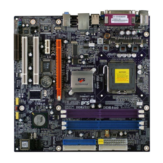
Page 10: Motherboard Components
Motherboard Components Introducing the Motherboard... - Page 11 Table of Motherboard Components LABEL COMPONENT 1 CPU Socket LGA775 socket for Pentium 4/Celeron D/ Pentium D CPUs 2 CPU_FAN CPU cooling fan connector 3 DDRII1~2 240-pin DDR2 SDRAM slots 4 DDR1~2 184-pin DDR SDRAM slots 5 ATX1 Standard 24-pin ATX power connector 6 FDD Floppy disk drive connector 7 IDE2...
- Page 12 Memo Introducing the Motherboard...
-
Page 14: Checking Jumper Settings
Checking Jumper Settings The following illustration shows the location of the motherboard jumpers. Pin 1 is labeled. Jumper Settings Jumper Type Description Setting (default) 1-2: NORMAL 2-3: CLEAR CLR_CMOS 3-pin Clear CMOS Before clearing the CMOS, make sure to CLR_CMOS turn off the system. -
Page 15: Connecting Case Components
Connecting Case Components After you have installed the motherboard into a case, you can begin con- necting the motherboard components. Refer to the following: Connect the CPU cooling fan cable to CPU_FAN. Connect the system cooling fan connector to SYS_FAN. Connect the case switches and indicator LEDs to the PANEL1. - Page 16 CPU_FAN/SYS_FAN: Cooling FAN Power Connectors Signal Name Function System Ground Power +12V +12V Sense Sensor CPU FAN control Users please note that the fan connector supports the CPU cooling fan of 1.1A~2.2A (26.4W max.) at +12V. ATX_12V1: ATX 12V Power Connector Signal Name Ground Ground...
- Page 17 Table A: DDR2 (memory module) QVL (Qualified Vendor List) The following DDR2 memory modules have been tested and qualified for use with this motherboard. Type Size Vendor Model Name Hynix HYMP532U646-E3 AA DDR2 256 MB NANYA NT256T64UH4A0F-5A SAMSUNG M378T3253FG0-GCCC A-DATA M2OHY2F3G3110A1B0Z Elixir M2U25664TUH4A0F-37B...
-
Page 18: Installing A Hard Disk Drive/Cd-Rom/Sata Hard Drive
Installing a Hard Dish Drive/CD-ROM/SATA Hard Drive This section describes how to install IDE devices such as a hard disk drive and a CD-ROM drive. About IDE Devices Your motherboard has two IDE channels interface. An IDE ribbon cable supporting two IDE devices is bundled with the motherboard. - Page 19 About SATA Connectors Your motherboard features two SATA connectors supporting a total of two drives. SATA , or Serial ATA (Advanced Technology Attachment) is the standard interface for the IDE hard drives which are currently used in most PCs. These connectors are well designed and will only fit in one orientation.
-
Page 20: Installing A Floppy Diskette Drive
Installing a Floppy Diskette Drive The motherboard has a floppy diskette drive (FDD) interface and ships with a diskette drive ribbon cable that supports one or two floppy diskette drives. You can install a 5.25-inch drive and a 3.5-inch drive with various capacities. The floppy diskette drive cable has one type of connector for a 5.25-inch drive and another type of connector for a 3.5-inch drive. -
Page 21: Installing Add-On Cards
Installing Add-on Cards The slots on this motherboard are designed to hold expansion cards and connect them to the system bus. Expansion slots are a means of adding or enhancing the motherboard’s features and capabilities. With these efficient facilities, you can increase the motherboard’s capabili- ties by adding hardware that performs tasks that are not part of the basic system. - Page 22 Follow these instructions to install an add-on card: Remove a blanking plate from the system case corresponding to the slot you are going to use. Install the edge connector of the add-on card into the expansion slot. Ensure that the edge connector is correctly seated in the slot. Secure the metal bracket of the card to the system case with a screw.
-
Page 23: Connecting Optional Devices
Connecting Optional Devices Refer to the following for information on connecting the motherboard’s optional devices: USB3~4: Front Panel USB headers The motherboard has four USB ports installed on the rear edge I/O port array. Additionally, some computer cases have USB ports at the front of the case. If you have this kind of case, use auxiliary USB connector to connect the front-mounted ports to the motherboard. - Page 24 AUDIO1: Front Panel Audio header This header allows the user to install auxiliary front-oriented microphone and line-out ports for easier access. Signal Name Function AUD_MIC Front Panel Microphone input signal AUD_GND Ground used by Analog Audio Circuits AUD_MIC_BIAS Microphone Power AUD_VCC Filtered +5V used by Analog Audio Circuits AUD_F_R...
- Page 25 SATA1~2: Serial ATA connectors These connectors are use to support the new Serial ATA devices for the highest date transfer rates (1.5 Gb/s), simpler disk drive cabling and easier PC assembly. It eliminates limitations of the current Parallel ATA interface. But maintains register compatibility and software compatibility with Parallel ATA.
-
Page 26: Connecting I/O Devices
Connecting I/O Devices The backplane of the motherboard has the following I/O ports: PS2 Mouse Use the upper PS/2 port to connect a PS/2 pointing device. PS2 Keyboard Use the lower PS/2 port to connect a PS/2 keyboard. Parallel Port (LPT1) Use LPT1 to connect printers or other parallel communications devices.
Need help?
Do you have a question about the P4M890T-M2 and is the answer not in the manual?
Questions and answers