Table of Contents
Advertisement
Copyright
This publication, including all photographs, illustrations and software, is protected un-
der international copyright laws, with all rights reserved. Neither this manual, nor any
of the material contained herein, may be reproduced without written consent of the au-
thor.
Version 1.0a
Disclaimer
The information in this document is subject to change without notice. The manufac-
turer makes no representations or warranties with respect to the contents hereof and
specifically disclaim any implied warranties of merchantability or fitness for any
particular purpose. The manufacturer reserves the right to revise this publication and
to make changes from time to time in the content hereof without obligation of the
manufacturer to notify any person of such revision or changes.
Trademark Recognition
Microsoft, MS-DOS and Windows are registered trademarks of Microsoft Corp.
MMX, Pentium, Pentium-II, Pentium-III, Celeron are registered trademarks of Intel
Corporation.
Other product names used in this manual are the properties of their respective owners
and are acknowledged.
Federal Communications Commission (FCC)
This equipment has been tested and found to comply with the limits for a Class B digi-
tal device, pursuant to Part 15 of the FCC Rules. These limits are designed to provide
reasonable protection against harmful interference in a residential installation. This
equipment generates, uses, and can radiate radio frequency energy and, if not in-
stalled and used in accordance with the instructions, may cause harmful interference
to radio communications. However, there is no guarantee that interference will not oc-
cur in a particular installation. If this equipment does cause harmful interference to
radio or television reception, which can be determined by turning the equipment off
and on, the user is encouraged to try to correct the interference by one or more of the
following measures:
−
Reorient or relocate the receiving antenna.
−
Increase the separation between the equipment and the receiver.
−
Connect the equipment onto an outlet on a circuit different from that to which
the receiver is connected.
−
Consult the dealer or an experienced radio/TV technician for help.
Shielded interconnect cables and a shielded AC power cable must be employed with
this equipment to ensure compliance with the pertinent RF emission limits governing
this device. Changes or modifications not expressly approved by the system's manu-
facturer could void the user's authority to operate the equipment.
i
Preface
Advertisement
Table of Contents

Related Manuals for ECS P4VXAD+


Summary of Contents for ECS P4VXAD+
- Page 1 Preface Copyright This publication, including all photographs, illustrations and software, is protected un- der international copyright laws, with all rights reserved. Neither this manual, nor any of the material contained herein, may be reproduced without written consent of the au- thor.
- Page 2 Declaration of Conformity This device complies with part 15 of the FCC rules. Operation is subject to the follow- ing conditions: − This device may not cause harmful interference, and − This device must accept any interference received, including interference that may cause undesired operation.
-
Page 3: Table Of Contents
Preface Features and Packing List Translations ¿ ù » ~ ! © | ¥ ¼ © w ¸ q ® Ñ Å Ò ¡ C CHAPTER 1 Introducing the Mainboard Introduction....................1 Checklist ....................1 Standard Items ....................1 Features ....................2 Choosing a Computer Case............... - Page 4 Advanced Chipset Features Option ............... 35 Integrated Peripherals Option ................ 40 Power Management Setup Option ..............44 PNP/PCI Configurations................48 PC Health Status Option................50 Frequency/Voltage Control................50 Load Fail-Safe Defaults Option..............51 Load Optimized Defaults Option..............51 Set Password Option..................52 Save &...
-
Page 5: Introducing The Mainboard
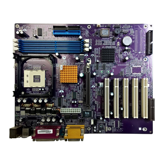
Introducing the Mainboard Thank you for choosing the P4VXAD+ mainboard. The P4VXAD+ mainboard is an ATX mainboard that uses a 4-layer printed circuit board and measures 305 mm x 244 mm. The mainboard features a Socket 478 that accommodates Intel Pentium 4 processors supporting front side bus (FSB) speeds of 400/533 MHz (133 MHz QDR). -
Page 6: Features
Processor The P4VXAD+ mainboard includes a mPGA Socket 478 that has the following features: • Supports up to a 400/533 MHz (133 MHz QDR) front side bus (FSB) • Accommodates Intel Pentium 4 processors Chipset The chipset on P4VXAD+ includes the P4X333 Northbridge and VT8235 Southbridge which are based on an innovative and scal- able architecture with proven reliability and performance. - Page 7 Expansion The mainboard comes with the following expansion options: Options • Five 32-bit PCI slots • One 4xAGP slot • A Communications Network Riser (CNR) slot (AC97 inter- face only) • Two IDE connectors which support four IDE channels and a floppy disk drive interface •...
-
Page 8: Choosing A Computer Case
There are many types of computer cases on the market. The mainboard com- plies with the specifications for the ATX system case. Some features on the mainboard are implemented by cabling connectors on the mainboard to indi- cators and switches on the system case. Ensure that your case supports all the features required. - Page 10 Table of Mainboard Components Label Component AGP1 Accelerated Graphics Port ATX1 Power connector AUDIO Mic/speaker-out connector Three volt realtime clock battery CASFAN Auxiliary case cooling fan Primary CD-in connector (Sony) Secondary CD-in connector (Panasonic) CNR1 Communications Networking Riser slot CPU SOCKET CPU Socket (mPGA478) CPUFAN Cooling fan for CPU...
-
Page 11: Installing The Mainboard
Installing the Mainboard Follow these safety precautions when installing the mainboard: • Wear a grounding strap attached to a grounded device to avoid damage from static electricity. • Discharge static electricity by touching the metal case of a safely grounded object before working on the mainboard. •... -
Page 12: Installing The Mainboard In A Case
Refer to the following illustration and instructions for installing the mainboard in a case: This illustration shows an ex- 2. Secure the mainboard with ample of a mainboard being screws where appropriate. installed in a tower-type case: Note: Do not overtighten the screws as this can stress the main- board. -
Page 13: Checking Jumper Settings
Checking Jumper Settings The following illustration shows the location of the mainboard jumpers. Pin 1 is labeled. Jumper Settings Jumper Type Description Setting (default) 3 pin Clear CMOS 1-2: Normal jumper 2-3: Clear CMOS 3 pin BIOS flash pro- 1-2: Unprotected tection jumper 2-3: Protected 3 pin... - Page 14 Turn the system on. The BIOS is returned to the de- fault settings. JP2 -This jumper is use to protect the BIOS from being unintentionally flashed. JP3 - This jumper enables to set the CPU frequency. JP4 - The CPU voltage is defined according to the VID table. VID4 and VID 3 are derived from the CPU only and cannot be changed.
-
Page 15: Connecting Case Components
After you have installed the mainboard into a case, you can begin connecting the mainboard components. Refer to the following: Connect the case power supply connector to ATX1. Connect the CPU cooling fan cable to CPUFAN. Connect the case cooling fan connector to CASFAN. - Page 16 SJI: Single-color LED header Signal Name ACPI LED ACPI LED 5VSB ACPI LED function: S4/S5 Light Blinking Blinking Dark J3: Single-color LED header Signal Name LED+ Ground...
-
Page 17: Front Panel Connector
Front Panel Connector The front panel connector (PANEL1) provides a standard set of switch and LED connectors commonly found on ATX or micro-ATX cases. Refer to the table below for information: PANEL1 Signal Function Signal Function Hard disk LED MSG LED [dual color HD_LED_P FP PWR/SLP (positive) -
Page 18: Installing Hardware
Installing the Processor Caution: When installing a CPU heatsink and cooling fan make sure that you DO NOT scratch the mainboard or any of the surface-mount resistors with the clip of the cooling fan. If the clip of the cooling fan scrapes across the mainboard, you may cause serious damage to the mainboard or its components. -
Page 19: Cpu Installation Procedure
CPU Installation Procedure The following illustration shows CPU installation components: Note: The pin-1 corner is marked with an arrow Follow these instructions to install the Retention Module and CPU: Remove the existing retention module (if applicable). Position the backplate against the underside of the mainboard;... - Page 20 Locate the CPU cut edge (the corner with the pinhole noticeably miss- ing). Align and insert the CPU correctly. Press the lever down. Apply thermal grease on top of the CPU. Put the CPU Fan down on the retention module and snap the four reten- tion legs of the cooling fan into place.
-
Page 21: Installing Memory Modules
Installing Memory Modules This mainboard accommodates 184-pin 2.5V unbuffered Double Data Rate (DDR) SDRAM memory modules. The memory chips must be standard or registered SDRAM (Synchronous Dynamic Random Access Memory). The memory bus can run at 100 MHz or 133 MHz or 166 MHz. If your proces- sor operates over a 100 MHz system bus, you can install DDR200 or DDR266 or DDR333 memory modules that operate over a 100 MHz or 133 MHz or 166 MHz memory bus respectively. -
Page 22: Installing A Hard Disk Drive/Cd-Rom
Installing a Hard Disk Drive/CD-ROM This section describes how to install IDE devices such as a hard disk drive and a CD-ROM drive. About IDE1 and IDE2 Devices Your mainboard has a primary and secondary IDE channel interface (IDE1 and IDE2). -
Page 23: Installing A Hard Disk Drive
Installing a Hard Disk Drive Install the hard disk drive into the drive cage in your system case. Plug the IDE cable into IDE1 (A): Note: Ribbon cable connectors are usually keyed so that they can only be installed correctly on the device connector. -
Page 24: Installing A Floppy Diskette Drive
Installing a Floppy Diskette Drive The mainboard has a floppy diskette drive (FDD) interface and ships with a diskette drive ribbon cable that supports one or two floppy diskette drives. You can install a 5.25-inch drive and a 3.5-inch drive with various capacities. The floppy diskette drive cable has one type of connector for a 5.25-inch drive and another type of connector for a 3.5-inch drive. - Page 25 PCI Slots PCI slots are used to install expansion cards that have the 32-bit PCI interface. 4xAGP Slot The AGP slot is used to install a graphics adapter that supports the 4xAGP specification and has a 4xAGP edge connector. Note: The layout is for reference only. The AGP slot may be different from your mainboard.
-
Page 26: Connecting Optional Devices
Connecting Optional Devices Refer to the following for information on connecting the mainboard’s optional devices: AUDIO1: Front Panel Audio header This header allows the user to install auxiliary front-oriented microphone and line-out ports for easier access. Signal Name Function AUD_MIC Front Panel Microphone input signal AUD_GND Ground used by Analog Audio Circuits... - Page 27 USB2/USB3: Front Panel USB connector The mainboard has two USB ports installed on the rear edge I/O port array. Additionally, some computer cases have USB ports at the front of the case. If you have this kind of case, use auxiliary USB connector USB2/USB3 to con- nect the front-mounted ports to the mainboard.
- Page 28 RAIDLED: IDE3/IDE4 array controller active LED This connector is used to show the activity of the IDE3/IDE4 HDD. The IDE LED is located on pins 1-2 of RAIDLED. You can attach the hard drive LED cable to pins 1-2. Signal Name IDE active...
- Page 29 IDE3/IDE4: Third/Fourth IDE connector These connectors are for Promise PDC20265R controller only. Connect one cable to each of the IDE connectors of the mainboard (IDE3 & IDE4 connec- tor). Please note the color orientation of the cable before attaching it to the mainboard.
-
Page 30: Connecting I/O Devices
The backplane of the mainboard has the following I/O ports: Parallel port (LPT1) Game port PS/2 mouse PS/2 Serial port Serial port Microphone keyboard ports COM 1 COM 2 Line-in Line-out PS/2 Mouse Use the upper PS/2 port to connect a PS/2 pointing device. PS/2 Keyboard Use the lower PS/2 port to connect a PS/2 keyboard. -
Page 31: External Connector Color Coding
External Connector Color Coding Many connectors now use standard colors as shown in the table below. Connector Color Analog VGA Blue Audio line-in Light blue Audio line-out Lime Digital monitor/flat panel White IEEE 1394 Grey Microphone Pink MIDI/game Gold Parallel Burgundy PS/2-compatible keyboard Purple... -
Page 32: Using Bios
Using BIOS The computer uses the latest Award BIOS with support for Windows Plug and Play. The CMOS chip on the mainboard contains the ROM setup instructions for configuring the mainboard BIOS. The BIOS (Basic Input and Output System) Setup Utility displays the system's configuration status and provides you with options to set system parameters. -
Page 33: Entering The Setup Utility
Entering the Setup Utility When you power on the system, BIOS enters the Power-On Self Test (POST) routines. POST is a series of built-in diagnostics performed by the BIOS. After the POST routines are completed, the following message appears: Press DEL to enter SETUP Pressing the delete key accesses the BIOS Setup Utility: Phoenix –... -
Page 34: Using Bios
If your mainboard has an item called Firmware Write Protect in Advanced BIOS features, disable it. (Firmware Write Protect prevents BIOS from being overwritten.) Create a bootable system disk. (Refer to Windows online help for infor- mation on creating a bootable system disk.) Download the Flash Utility and new BIOS file from the manufacturer's Web site. -
Page 35: Standard Cmos Features
Standard CMOS Features This option displays basic information about your system. Phoenix – AwardBIOS CMOS Setup Utility Standard CMOS Features Item Help Date (mm:dd:yy) Tue, July 11 2001 Time (hh:mm:ss) 12 : 8 : 59 Menu Level IDE Primary Master Change the day, month, IDE Primary Slave year and century. - Page 36 IDE HDD Auto-Detection Press <Enter> while this item is highlighted to prompt the Setup Utility to automatically detect and configure an IDE device on the IDE channel. Note: If you are setting up a new hard disk drive that supports LBA mode, more than one line will appear in the parameter box.
-
Page 37: Advanced Bios Setup Option
Advanced BIOS Setup Option This option defines advanced information about your system. Phoenix – AwardBIOS CMOS Setup Utility Advanced BIOS Features Item Help Anti-Virus Protection [Disabled] CPU L1 & L2 Cache [Enabled] Menu Level CPU L2 Cache ECC Checking [Enabled] Quick Power On Self Test [Enabled] Allows you to choose... - Page 38 First/Second/Third Boot Device (Floppy/HDD-0/CD-ROM) Use these three items to select the priority and order of the devices that your system searches for an operating system at start-up time. Boot Other Device (Enabled) When enabled, the system searches all other possible locations for an operat- ing system if it fails to find one in the devices specified under the First, Second, and Third boot devices.
-
Page 39: Advanced Chipset Features Option
condition and advises appropriate action to protect the data. Report No FDD for WIN95 (Yes) Select Yes to release IRQ6 when the system contains no floppy drive, for compatibility with Windows 95 logo certification. Video BIOS Shadow (Enabled) This function, when enabled allows VGA BIOS to be copied to the system DRAM for enhanced performance. - Page 40 DRAM Clock/Drive Control Scroll to this item and press <Enter> to view the following screen: Phoenix – AwardBIOS CMOS Setup Utility DRAM Clock/Drive Control Item Help Current FSB Frequency Current DRAM Frequency Menu Level DRAM Clock [By SPD] DRAM Timing [Manual] SDRAM CAS Latency Bank Interleave...
- Page 41 Precharge to Active (3T) This item is used to designate the minimum Row Precharge time of the SDRAM devices on the module. DRAM must continually be refreshed or it will lose its data. Normally, DRAM is refreshed entirely as the result of a single request. This option allows you to de- termine the number of CPU clocks allocated for the Row Address Strobe (RAS) to accumulate its charge before the DRAM is refreshed.
- Page 42 for graphics memory. We recommend that you leave this item at the default value. AGP Mode (4X) This item allows you to enable or disable the caching of display data for the processor video memory. Enabling AGP-4X Mode can greatly improve the display speed.
- Page 43 CPU & PCI Bus Control Scroll to this item and press <Enter> to view the following screen: Phoenix – AwardBIOS CMOS Setup Utility CPU & PCI Bridge Control Item Help CPU to PCI Write Buffer [Enabled] PCI Master 0 WS Write [Enabled] Menu Level PCI Delay Transaction...
-
Page 44: Integrated Peripherals Option
Integrated Peripherals Option These options display items that define the operation of peripheral compo- nents on the system's input/output ports. Phoenix – AwardBIOS CMOS Setup Utility Integrated Peripherals Item Help VIA OnChip IDE Device [Press Enter] VIA On Chip PCI Device [Press Enter] Menu Level Super I/O Device... - Page 45 field to Disabled if the interface does not support prefetching. IDE Primary/Secondary Master/Slave PIO (Auto) Each IDE channel supports a master device and a slave device. These four items let you assign which kind of PIO (Programmed Input/Output) is used by IDE devices.
- Page 46 Onboard RAID ROM (Disabled) This item allows you to enable or disable the onboard RAID ROM function. Press <Esc> to return to the Integrated Peripherals screen. SuperIO Device Scroll to this item and press <Enter> to view the following screen: Phoenix –...
- Page 47 tion at a time. Onboard Parallel Port (378/IRQ7) This option is used to assign the I/O address and interrupt request (IRQ) for the onboard parallel port. Parallel Port Mode (ECP) Enables you to set the data transfer protocol for your parallel port. There are four options: SPP (Standard Parallel Port), EPP (Enhanced Parallel Port), ECP (Extended Capabilities Port) and ECP+EPP.
-
Page 48: Power Management Setup Option
Power Management Setup Option This option lets you control system power management. The system has vari- ous power-saving modes including powering down the hard disk, turning off the video, suspending to RAM, and software power down that allows the sys- tem to be automatically resumed by certain events. - Page 49 the suspend mode is equivalent to a software power down. If you select S3 (STR), the suspend mode is a suspend to RAM - the system shuts down with the exception of a refresh current to the system memory. *This item is only available when the mainboard supports the S3 feature. Power Management Option (User Define) This item acts like a master switch for the power-saving modes and hard disk timeouts.
- Page 50 IRQ/Event Activity Detect Scroll to this item and press <Enter> to view the following screen: Phoenix – AwardBIOS CMOS Setup Utility IRQ/Event Activity Detect Item Help PS/2 KB /WakeUp from S3/S4/S5 [Disabled] USB Resume from S3 [Enabled] Menu Level [OFF] LPT &...
- Page 51 ing mode. Wake Up On LAN/Ring (Disabled) Use this item to enable LAN or modem activity to wakeup the system from a power saving mode. RTC Alarm Resume (Disabled) When set to Enabled, the following two fields become available and you can set the date (day of the month), hour, minute and second to turn on your sys- tem.
-
Page 52: Pnp/Pci Configurations
PNP/PCI Configurations These options configure how PnP (Plug and Play) and PCI expansion cards oper- ate in your system. Both the ISA and PCI buses on the Mainboard use system IRQs (Interrupt ReQuests) and DMAs (Direct Memory Access). You must set up the IRQ and DMA assignments correctly through the PnP/PCI Configurations Setup utility for the mainboard to work properly. - Page 53 IRQ Resources The submenu allows you to individually assign an interrupt type for interrupts IRQ-3 to IRQ-15. Phoenix – AwardBIOS CMOS Setup Utility PnP/PCI Configurations Item IRQ-3 assigned to [PCI Device] IRQ-4 assigned to [PCI Device] Menu Level IRQ-5 assigned to [PCI Device] IRQ-7 assigned to [PCI Device]...
-
Page 54: Pc Health Status Option
PC Health Status Option On mainboards that support hardware monitoring, this item lets you monitor the parameters for critical voltages, critical temperatures, and fan speeds: Phoenix – AwardBIOS CMOS Setup Utility PC Health Status Item Help Shutdown Temperature [Disabled] CPU VCORE Menu Level 2.50V 3.30V... -
Page 55: Load Fail-Safe Defaults Option
CPU Ratio (Auto) Use this item to select a multiplier for the system frontside bus (FSB) fre- quency. The value of the multiplier must be set so that: Multiplier x Frontside Bus Frequency = CPU Clock Speed For example, if you have a processor that is rated to run at 450 MHz and the system is running a frontside bus frequency of 100 MHz, you should select a multiplier of 4.5 so that: 4.5 (Multiplier) x 100 MHz (frontside bus) = 450 MHz (CPU clock) -
Page 56: Set Password Option
Set Password Option This item can be used to install a password. To install a password, follow these steps: Highlight the item Set Password on the main menu and press <Enter>. The password dialog box appears. Enter Password: If you are installing a new password, type in the password. You cannot use more than eight characters or numbers. -
Page 57: Using The Mainboard Software
Using the Mainboard Software The support software CD-ROM that is included in the mainboard package contains all the drivers and utility programs needed to properly run the bun- dled products. Below you can find a brief description of each software program, and the location for your mainboard version. -
Page 58: Running Setup
Setup Tab Setup Click the Setup button to run the software installation program. Select from the menu which software you want to install. Browse The Browse CD button is the standard Windows command that allows you to open Windows Explorer and show the contents of the support CD. - Page 59 Note: The following screens are examples only. The screens and driver lists will be different according to the mainboard you are installing. The mainboard identification is located in the upper left-hand corner. Click Next. The following screen appears: Check the box next to the items you want to install. The default options are recommended.
-
Page 60: Manual Installation
Insert the CD in the CD-ROM drive and locate the PATH.DOC file in the root directory. This file contains the information needed to locate the drivers for your mainboard. Look for the chipset and mainboard model; then browse to the directory and path to begin installing the drivers. - Page 61 We strongly recommend users to install this free anti-virus software to help protect your system against viruses. MediaRing Talk – Telephony Software To install the MediaRing Talk voice modem software for the built-in modem, go directory \UTILITY\MEDIARING TALK, then MRTALK- SETUP72.EXE to install the application software.
Need help?
Do you have a question about the P4VXAD+ and is the answer not in the manual?
Questions and answers