Table of Contents
Advertisement
Quick Links
Copyright
This publication, including all photographs, illustrations and software,
is protected under international copyright laws, with all rights re-
served. Neither this manual, nor any of the material contained herein,
may be reproduced without written consent of the author.
Version 1.0b
Disclaimer
The information in this document is subject to change without notice.
The manufacturer makes no representations or warranties with re-
spect to the contents hereof and specifically disclaims any implied
warranties of merchantability or fitness for any particular purpose.
The manufacturer reserves the right to revise this publication and to
make changes from time to time in the content hereof without obliga-
tion of the manufacturer to notify any person of such revision or
changes.
Trademark Recognition
Microsoft, MS-DOS and Windows are registered trademarks of Mi-
crosoft Corp.
MMX, Pentium, Pentium-II, Pentium-III, Pentium 4, Celeron are reg-
istered trademarks of Intel Corporation.
Other product names used in this manual are the properties of their
respective owners and are acknowledged.
Preface
Copyright © 2001
All Rights Reserved
P4VXASD, V1.0b
Advertisement
Table of Contents

Related Manuals for ECS P4VXASD


Summary of Contents for ECS P4VXASD
- Page 1 Corp. MMX, Pentium, Pentium-II, Pentium-III, Pentium 4, Celeron are reg- istered trademarks of Intel Corporation. Other product names used in this manual are the properties of their respective owners and are acknowledged. Copyright © 2001 All Rights Reserved P4VXASD, V1.0b...
- Page 2 Federal Communications Commission (FCC) This equipment has been tested and found to comply with the limits for a Class B digital device, pursuant to Part 15 of the FCC Rules. These limits are designed to provide reasonable protection against harmful interference in a residential installation. This equipment gen- erates, uses, and can radiate radio frequency energy and, if not installed and used in accordance with the instructions, may cause harmful interference to radio communications.
- Page 3 Declaration of Conformity This device complies with part 15 of the FCC rules. Operation is sub- ject to the following conditions: − This device may not cause harmful interference, and − This device must accept any interference received, includ- ing interference that may cause undesired operation. Canadian Department of Communications This class B digital apparatus meets all requirements of the Cana- dian Interference-causing Equipment Regulations.
- Page 4 About the Manual The manual consists of the following: Chapter 1 Describes features of the main- board, and provides a shipping Introducing the Mainboard checklist. ⇒ Go to page 1 Chapter 2 Describes installation of main- board components. Installing the Mainboard ⇒...
-
Page 5: Table Of Contents
Preface CHAPTER 1 Introducing the Mainboard Introduction ..................1 Checklist ..................2 Standard Items ..................2 Optional Accessories ................2 Features...................3 Mainboard Components ..............5 Choosing a Computer Case ............6 CHAPTER 2 Installing the Mainboard Safety Precautions................7 Quick Guide ..................8 Checking Jumper Settings...............9 Setting Jumpers ................... - Page 6 Standard CMOS Setup Page.............. 37 Advanced Setup Page ................ 39 Power Management Setup Page ............42 PCI / Plug and Play Setup Page............44 Load Optimal Settings............... 45 Load Best Performance Settings............45 Features Setup Page................45 CPU PnP Setup Page ................. 47 Hardware Monitor Page ..............
-
Page 7: Introducing The Mainboard
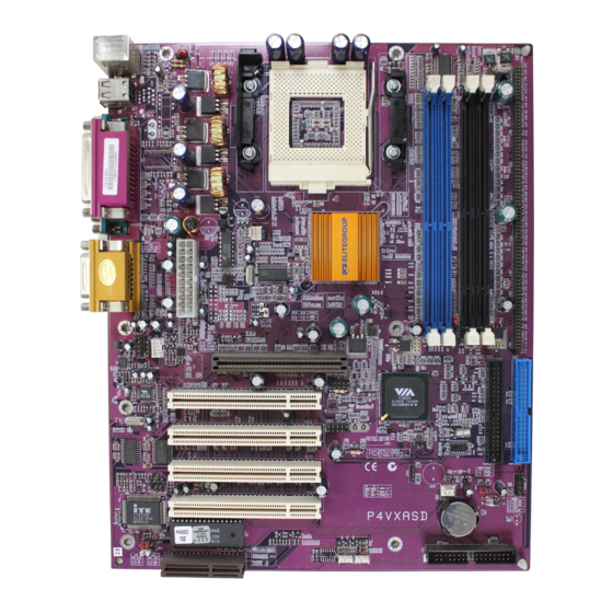
Introducing the Mainboard This mainboard has a Socket 423 for the Intel Pentium 4 type processors supporting front side bus (FSB) speeds up to 400 MHz. This mainboard has the VIA VT8753 (P4X266) Northbridge and VT8233 Southbridge chipsets that support AC’97 audio codec, and provide Ultra DMA 33/66/100 function. -
Page 8: Checklist
Compare the mainboard’s package contents with the following checklist: Standard Items • One mainboard • The User’s Manual • One diskette drive ribbon cable • One IDE drive ribbon cable • Software support CD • One Retention Module Optional Accessories You can purchase the following optional accessories for this mainboard. -
Page 9: Features
• The PGA Socket 423 Processor • Accommodates Intel Pentium 4 CPUs • Supports a front-side bus (FSB) of 400 MHz Chipset There are VT8753 Northbridge and VT8233 Southbridge in this chipset in accordance with an innovative and scalable architecture with proven reliability and performance. - Page 10 AC 97 Audio The AC’97 Audio codec is compliant with the AC’ Codec 97 2.1 specification, and supports 18-bit ADC (Analog Digital Converter) and DAC (Digital Ana- log Converter) resolution as well as 18-bit stereo full-duplex codec with independent and variable sampling rates.
-
Page 12: Choosing A Computer Case
There are many types of computer cases on the market. The mainboard complies with the specifications for the ATX sys- tem case. Some features on the mainboard are implemented by cabling connectors on the mainboard to indicators and switches on the system case. Ensure that your case supports all the features required. -
Page 13: Installing The Mainboard
Installing the Mainboard Follow these safety precautions when installing the mainboard: • Wear a grounding strap attached to a grounded device to avoid damage from static electricity. • Discharge static electricity by touching the metal case of a safely grounded object before working on the mainboard. -
Page 14: Quick Guide
This Quick Guide suggests the steps you can take to assem- ble your system with the mainboard. The following table provides a reference for installing specific components: Locating Mainboard Components Go to page 5 Setting Jumpers Go to page 9 Installing the Mainboard in a Case Go to page 14 Installing Case Components... -
Page 15: Setting Jumpers
This section explains how to set jumpers for correct configura- tion of the mainboard. Setting Jumpers Use the mainboard jumpers to set system configuration op- tions. Jumpers with more than one pin are numbered. When setting the jumpers, ensure that the jumper caps are placed on the correct pins. -
Page 16: Checking Jumper Settings
Checking Jumper Settings The following illustration shows the location of the mainboard jumpers. Pin 1 is labeled. -
Page 17: Jumper Settings
Jumper Settings Jumper Description Setting (default) JBAT1 Clear CMOS 1-2: Normal JBAT1 jumper 2-3: Clear CMOS JP1A1 CPU Clock Short 1-2: 100M JP1A1 Open 2-3: 133M JP1B1 CPU Clock Short 2-3: 100M JP1B1 Open 1-2: 133M DRAM Volt- Short 1-2: 3.3V Open 1-2: 2.5V DDR/SDR Short all J2A/B/C/D:... - Page 18 Wake on 1-2: 5V Keyboard/ 2-3: 5VSB USB activity Flash ROM 1-2: 5V Voltage 2-3: 3.3V (VCC) Flash ROM 1-2: 2M Size 2-3: 4M JBAT1: Clear CMOS Jumper Use this jumper to clear the contents of the CMOS memory. You may need to clear the CMOS memory if the settings in the Setup Utility are incorrect and prevent your mainboard from operating.
- Page 19 JP3: Flash ROM Voltage (VCC) This jumper enables to select voltage for Flash ROM. JP4: Flash ROM Size This jumper enables to select size for Flash ROM.
-
Page 20: Installing The Mainboard In A Case
Refer to the following illustration and instructions for installing the mainboard in a case: This illustration shows 2. Secure the mainboard with an example of a main- screws where appropriate. board being installed in a tower-type case: Note: Do not over- tighten the screws as this can stress the... -
Page 21: Connecting Case Components
After you have installed the mainboard into a case, you can begin connecting the mainboard components. Refer to the fol- lowing: 1. Connect the case power supply connector to CN5. 2. Connect the CPU cooling fan cable to CPU_FAN. 3. Connect the case cooling fan connector to SYS- TEM_FAN. -
Page 22: The Panel1 And Panel2 Connectors
The Panel1 and Panel2 Connectors PANEL1 If there is a headphone jack or/and a microphone jack on the front panel, connect the cables to the PANEL1 on the mainboard. Device Pins Line Out (L) 9,10 Line Out(L) (Pin 9,10) Line Out (R) 5, 6 MIC In 1, 2... -
Page 23: Installing Hardware
Installing the Processor Caution: When installing a CPU heatsink and cooling fan make sure that you DO NOT scratch the mainboard or any of the surface-mount resistors with the clip of the cooling fan. If the clip of the cooling fan scrapes across the main- board, you may cause serious damage to the mainboard or its components. - Page 24 CPU Installation Procedure The following illustration shows CPU installation components: Note: The pin-1 corner on the CPU and socket is empty. Follow these instructions to install the CPU: 1. Pull the CPU socket locking lever away from the socket to unhook it and raise the locking lever to the upright position.
- Page 25 3. Swing the locking lever down and hook it under the latch on the edge of the socket. 4. Apply thermal grease to the top of the CPU. Lower the CPU fan/heatsink unit onto the CPU and CPU socket and then use the retention module clamps to snap the fan/heatsink into place (refer to diagram below).
- Page 26 6. Plug the CPU fan power cable into the CPU cooling fan power supply (CPU_FAN) on the mainboard.
-
Page 27: Installing Memory Modules
Installing Memory Modules This mainboard accommodates 168-pin 3.3V/184-pin 2.5V unbuffered SDRAM memory modules. The memory chips must be standard or registered SDRAM (Synchronous Dy- namic Random Access Memory). The CPU supports 100MHz system bus. The SDRAM DIMMs and DDRs can synchronously work with 100 MHz or operates over a 133 MHz system bus. - Page 28 The mainboard accommodates two memory modules. You must install at least one module in any of the three slots. Each module can be installed with up to 1 GB of memory; total memory capacity is 2 GB. Refer to the following to install the memory modules. 1.
-
Page 29: Installing A Hard Disk Drive/Cd-Rom
Installing a Hard Disk Drive/CD-ROM This section describes how to install IDE devices such as a hard disk drive and a CD-ROM drive. About IDE Devices Your mainboard has a primary and secondary IDE channel in- terface (IDE1 and IDE2). An IDE ribbon cable supporting two IDE devices is bundled with the mainboard. - Page 30 Installing a Hard Disk Drive 1. Install the hard disk drive into the drive cage in your system case. 2. Plug the IDE cable into IDE1 (A). Note: Ribbon cable connectors are usually keyed so that they can only be installed correctly on the device connector.
- Page 31 Installing a CD-ROM/DVD Drive 1. Install the CD-ROM/DVD drive into the drive cage in your system case. 2. Plug the IDE cable into IDE1 (A). If you have already installed an HDD, use the other connector on the IDE cable. Note: Ribbon cable connectors are usually keyed so that they can only be installed correctly on the device connector.
-
Page 32: Installing A Floppy Diskette Drive
Installing a Floppy Diskette Drive The mainboard has a floppy diskette drive (FDD) interface and ships with a diskette drive ribbon cable that supports one or two floppy diskette drives. You can install a 5.25-inch drive and a 3.5-inch drive with various capacities. The floppy disk- ette drive cable has one type of connector for a 5.25-inch drive and another type of connector for a 3.5-inch drive. -
Page 33: Installing Add-On Cards
Installing Add-on Cards This mainboard has four 32-bit PCI (Peripheral Components Interconnect) expansion slots, one 4xAGP slot, and one CNR slot. 4xAGP Slot The 4xAGP slot is used to install a graphics adapter that supports the 4xAGP specifica- tions and has a 4xAGP edge connector. PCI Slots PCI slots are used to install expansion cards that have the 32-bit PCI interface. - Page 34 1. Remove a blanking plate from the system case corre- sponding to the slot you are going to use. 2. Install the edge connector of the add-on card into the expansion slot. Ensure that the edge connector is cor- rectly seated in the slot. 3.
-
Page 35: Connecting Optional Devices
Connecting Optional Devices Refer to the following for information on connecting the main- board’s optional devices:... - Page 36 J12: Sleep Switch This header is connected to the sleep button for suspending the computer’s activity if pushing the button. Or, the computer is automatically suspended after passing a period of time. SPK1: Speaker Connector Connect the cable from the PC speaker to the SPK1 header on the mainboard.
- Page 37 matically resumes the system. You must enable this item us- ing the Power Management page of the Setup Utility. See Chapter 3 for more information. J16: LAN LED Indicator This connector is attached to LAN device that needs a LED indicator.
-
Page 38: Connecting I/O Devices
The backplane of the mainboard has the following I/O ports: Parallel port (LPT1) Game port PS/2 port mouse PS/2 Serial port Serial port Microphone keyboard ports COM 1 COM 2 Line-in Line-out PS/2 Mouse Use the upper PS/2 port to connect a PS/2 pointing device. -
Page 39: External Connector Color Coding
External Connector Color Coding Many connectors now use standard colors as shown in the table below. Connector Color Analog VGA Blue Audio line-in Light blue Audio line-out Lime Digital monitor/flat panel White IEEE 1394 Grey Microphone Pink MIDI/Game Gold Parallel Burgundy PS/2-compatible keyboard Purple... -
Page 40: Using Bios
Using BIOS The BIOS Setup Utility records computer’s settings and infor- mation, such as date and time, type of installed hardware, and various configuration settings. Your computer applies the in- formation to initialize all the components when booting up, and basic functions of overall coordination between system components. -
Page 41: The Standard Configuration
The Standard Configuration A standard configuration has already been set in the Setup Utility. However, we recommend that you read this chapter in case you need to make any changes in the future. This Setup Utility should be used: • when changing the system configuration •... -
Page 42: Entering The Setup Utility
Entering the Setup Utility When you power on the system, BIOS enters the Power-On Self Test (POST) routines. POST is a series of built-in diag- nostics performed by the BIOS. After the POST routines are completed, the following message appears: Press DEL to enter SETUP Pressing the delete key accesses the AMI BIOS Setup Util-... -
Page 43: Using Bios
When you start the Setup Utility, the main menu appears. The main menu of the Setup Utility displays a list of the options that are available. A highlight indicates which option is cur- rently selected. Use the cursor arrow keys to move the highlight to other options. - Page 44 Date and Time The Date and Time items show the current date and time on the computer. If you are running a Windows OS, these items are automatically updated whenever you make changes to the Windows Date and Time Properties utility. IDE Pri Master/Slave and IDE Sec Master/Slave Use these items to configure devices connected to the Pri- mary and Secondary IDE channels.
-
Page 45: Advanced Setup Page
Advanced Setup Page This page sets up more advanced information about your sys- tem. Be more careful to this page. Any changes can affect the operation of your computer. AMIBIOS SETUP – ADVANCED SETUP (C) 2000 American Megatrends, Inc. All Rights Reserved Quick Boot Enabled AGP Comp. - Page 46 at system start-up time. Floppy Drive Swap If you have two diskette drives installed and you enable this item, drive A becomes drive B and drive B becomes drive A. Floppy Drive Seek If you enable this item, your system will check all floppy disk drives at start up.
- Page 47 (column address strobe). It is recommended that you leave this item at the default value. The 2T setting requires faster memory that specifically supports this mode. SDRAM Bank Interleave Enable this item to increase SDRAM memory speed. When enabled, separate memory banks are set for odd and even addresses and the next byte of memory can be accessed while the current byte is being refreshed.
-
Page 48: Power Management Setup Page
Power Management Setup Page This page sets some of the parameters for system power management operation. AMIBIOS SETUP – POWER MANAGEMENT SETUP (C) 2000 American Megatrends, Inc. All Rights Reserved ACPI Aware O/S Power Management/APM Enabled Video Power Down Mode Suspend Hard Disk Power Down Mode Standby... - Page 49 Standby Time Out (Minute) This sets the timeout for Standby mode in minutes. If the time selected passes without any system activity, the computer will enter power-saving Standby mode. Suspend Time Out (Minute) This sets the timeout for Suspend mode in minutes. If the time selected passes without any system activity, the computer will enter power-saving Suspend mode.
-
Page 50: Pci / Plug And Play Setup Page
PCI / Plug and Play Setup Page This page sets some of the parameters for devices installed on the PCI bus and devices that use the system plug and play capability. AMIBIOS SETUP – PCI / PLUG AND PLAY SETUP (C) 2000 American Megatrends, Inc. -
Page 51: Load Optimal Settings
Load Optimal Settings If you select this item and press Enter a dialog box appears. If you press Y, and then Enter, the Setup Utility loads a set of fail-safe default values. These default values are not very de- manding and they should allow your system to function with most kinds of hardware and memory chips. - Page 52 OnBoard Serial Port A/B Use these items to enable or disable the onboard COM1/2 se- rial port, and to assign a port address. OnBoard Parallel Port Use this item to enable or disable the onboard LPT1 parallel port, and to assign a port address. The Auto setting will detect and available address.
-
Page 53: Cpu Pnp Setup Page
This item enables or disables the MC’97 modem chip. USB Controller Use this item to select the USB ports or disabled. USB Device Legacy Support This item allows you to enable the USB device, if you have in- stalled a USB device on the system board. CPU PnP Setup Page This page helps you manually configure the mainboard for the CPU. -
Page 54: Hardware Monitor Page
Hardware Monitor Page This page sets some of the parameters for the hardware monitoring function of this mainboard. AMIBIOS SETUP – HARDWARE MONITOR (C) 2000 American Megatrends, Inc. All Rights Reserved *** System Hardware *** Vocore 1.632V Vcc 2.5V 2.496V Vcc 3.3V 3.392V Vcc 5V... -
Page 55: Change Password
Change Password If you highlight this item and press Enter, a dialog box appears that you can enter a Supervisor password. You can enter no more than six letters or numbers. Press Enter after you have typed in the password. There will be the second dialog box asking you to retype the password for confirmation. -
Page 56: Using The Mainboard Software
Using the Mainboard Software The support software CD-ROM that is included in the main- board package contains all the drivers and utility programs needed to properly run the bundled products. Below you can find a brief description of each software program, and the lo- cation for your mainboard version. -
Page 57: Auto-Installing Under Windows 98
The Auto-install CD-ROM makes it easy for you to install the drivers and software for your mainboard. Note: If the Auto-install CD-ROM does not work on your system, you can still install drivers through the file manager for your OS (for example, Windows Ex- plorer). - Page 58 Follow these instructions to install device drivers and software for the mainboard: 1. Click Setup. The installation program begins: Mainboard ID Note: The following screens are examples only. The screens and driver lists will be different according to the mainboard you are installing. The mainboard identification is located in the upper left-hand corner.
- Page 59 5. Follow the instructions on the screen to install the items. Drivers and software are automatically installed in sequence. Follow the onscreen instructions, confirm commands, and al- low the computer to restart after each installation. Browse CD The Browse CD button is the standard Windows command that allows you to open Windows Explorer and show the con- tents of the support CD.
-
Page 60: Manual Installation
Insert the CD in the CD-ROM drive and locate the PATH.DOC file in the root directory. This file contains the information needed to locate the drivers for your mainboard. Look for the chipset and mainboard model; then browse to the directory and path to begin installing the drivers. - Page 61 2000/ME/98SE and Windows NT. Check the readme.txt and install the appropriate anti-virus software for your operating system. We strongly recommend users to install this free anti-virus software to help protect your system against viruses. Note: Update your virus software regularly to protect against new viruses.
- Page 62 Language Genius The Language Genius is a software–based product that helps you to learn new languages. To install the Language Genius software program run SETUP.EXE from the following directory: \UTILITY\LANGUAGE GENIUS\ENG\LANGUAGEGENIUS PageABC The PageABC application software enables you to create your own home page.
-
Page 63: Setting Jumpers
Setting Jumpers Jumper Settings Jumper Description Setting (default) JBAT1 Clear CMOS 1-2: Normal JBAT1 jumper 2-3: Clear CMOS JP1A1 CPU Clock Short 1-2: 100M JP1A1 Open 2-3: 133M JP1B1 CPU Clock Short 2-3: 100M JP1B1 Open 1-2: 133M DRAM Volt- Short 1-2: 3.3V Open 1-2: 2.5V DDR/SDR... - Page 64 DDR/SDR Short all J3A/B/C/D: J3A/B/C/D DRAM Type DDR1, DDR2 Selector Open all J3A/B/C/D: DIMM1, DIMM2 Wake on 1-2: 5V Keyboard/ 2-3: 5VSB USB activity Flash ROM 1-2: 5V Voltage 2-3: 3.3V (VCC) Flash ROM 1-2: 2M Size 2-3: 4M JBAT1: Clear CMOS Jumper Use this jumper to clear the contents of the CMOS memory.
- Page 65 J2A/J2B/J2C/J2D: DDR/SDR DRAM Type Selec- This jumper enables to select the type of DDR or SDR DRAM. J3A/J3B/J3C/J3D: DDR/SDR DRAM Type Selec- This jumper enables to select the type of DDR or SDR DRAM. JP2: Wake on Keyboard/USB activity This jumper enables any USB keyboard activity to power up a system previously in a standby or sleep state.
-
Page 66: The Panel1 And Panel2 Connectors
The Panel1 and Panel2 Connectors PANEL1 If there is a headphone jack or/and a microphone jack on the front panel, connect the cables to the PANEL1 on the mainboard. Device Pins Line Out (L) 9,10 Line Out(L) (Pin 9,10) Line Out (R) 5, 6 MIC In 1, 2...
Need help?
Do you have a question about the P4VXASD and is the answer not in the manual?
Questions and answers