Table of Contents
Advertisement
Copyright
This publication, including all photographs, illustrations and software, is protected un-
der international copyright laws, with all rights reserved. Neither this manual, nor any
of the material contained herein, may be reproduced without written consent of the au-
thor.
Version 5.0a
Disclaimer
The information in this document is subject to change without notice. The manufac-
turer makes no representations or warranties with respect to the contents hereof and
specifically disclaims any implied warranties of merchantability or fitness for any par-
ticular purpose. The manufacturer reserves the right to revise this publication and to
make changes from time to time in the content hereof without obligation of the manu-
facturer to notify any person of such revision or changes.
Trademark Recognition
Microsoft, MS-DOS and Windows are registered trademarks of Microsoft Corp.
MMX, Pentium, Pentium-II, Pentium-III, Celeron are registered trademarks of Intel
Corporation.
Other product names used in this manual are the properties of their respective owners
and are acknowledged.
Federal Communications Commission (FCC)
This equipment has been tested and found to comply with the limits for a Class B digi-
tal device, pursuant to Part 15 of the FCC Rules. These limits are designed to provide
reasonable protection against harmful interference in a residential installation. This
equipment generates, uses, and can radiate radio frequency energy and, if not in-
stalled and used in accordance with the instructions, may cause harmful interference
to radio communications. However, there is no guarantee that interference will not oc-
cur in a particular installation. If this equipment does cause harmful interference to
radio or television reception, which can be determined by turning the equipment off
and on, the user is encouraged to try to correct the interference by one or more of the
following measures:
Reorient or relocate the receiving antenna.
Increase the separation between the equipment and the receiver.
Connect the equipment onto an outlet on a circuit different from that to which the
receiver is connected.
Consult the dealer or an experienced radio/TV technician for help.
Shielded interconnect cables and a shielded AC power cable must be employed with
this equipment to ensure compliance with the pertinent RF emission limits governing
this device. Changes or modifications not expressly approved by the system's manu-
facturer could void the user's authority to operate the equipment.
Preface
Advertisement
Table of Contents

Related Manuals for ECS P4VXASD2


Summary of Contents for ECS P4VXASD2
- Page 1 Preface Copyright This publication, including all photographs, illustrations and software, is protected un- der international copyright laws, with all rights reserved. Neither this manual, nor any of the material contained herein, may be reproduced without written consent of the au- thor.
- Page 2 Declaration of Conformity This device complies with part 15 of the FCC rules. Operation is subject to the follow- ing conditions: This device may not cause harmful interference, and This device must accept any interference received, including interference that may cause undesired operation. Canadian Department of Communications This class B digital apparatus meets all requirements of the Canadian Interference- causing Equipment Regulations.
-
Page 3: Table Of Contents
Preface CHAPTER 1 Introducing the Mainboard Introduction....................1 Checklist ....................1 Standard Items ....................1 Features ....................2 Choosing a Computer Case............... 3 Mainboard Components ................4 CHAPTER 2 Installing the Mainboard Safety Precautions..................5 Quick Guide....................5 Installing the Mainboard in a Case............. 6 Checking Jumper Settings ................. - Page 4 Load Best Performance Settings..............32 Features Setup Page..................32 CPU PnP Setup Page ..................34 Hardware Monitor Page................. 34 Change Password................... 35 Exit ........................ 35 錯誤! 尚未定義書籤。 CHAPTER 4 錯誤! 尚未定義書籤。 Using the Mainboard Software 錯誤 尚未定義書籤。 About the Software CD-ROM........錯誤...
-
Page 5: Introducing The Mainboard
Introducing the Mainboard Thank you for choosing this mainboard. This mainboard has a Socket-478 processor socket for Intel Pentium 4 type of processors supporting front side bus (FSB) speeds up to 533 MHz. This mainboard incorporates P4X333 Northbridge VT8235/8233A(CE) Southbridge chipsets that support AC 97 audio codec, and provide Ultra DMA 33/66/100/133 function. -
Page 6: Features
• The PGA Socket 478 Processor • Supports Intel Pentium 4 series CPUs • Supports up to 533 MHz Front-Side Bus Chipset The P4X333 Northbridge and VT8235 / 8233A(CE) Southbridge in this chipset are in accordance with an innova- tive and scalable architecture with proven reliability and performance. -
Page 7: Choosing A Computer Case
• One MIDI/game port • Six USB ports (two back-panel ports, onboard USB headers providing maximum four extra ports: headers USB1 & USB2) • Audio jacks for microphone, line-in and line-out • Built-in 10BaseT/100BaseTX Ethernet LAN Fast Ethernet • VT8235 integrates Fast Ethernet MAC and VT6103 LAN PHY in compliance with IEEE802.3u 100BASE-TX, (for VT8235 SB 10BASE-T and ANSI X3.263 TP-PMD standards... -
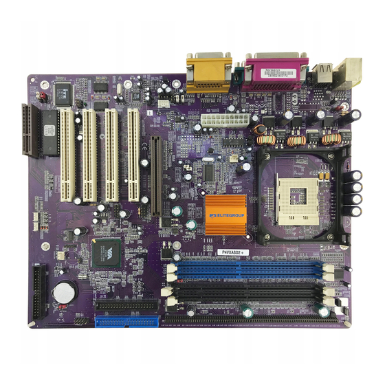
Page 8: Mainboard Components
Note: Any jumpers or connectors on your mainboard that cannot be found on the layout are for manufacturing test only. -
Page 9: Installing The Mainboard
Installing the Mainboard Follow these safety precautions when installing the mainboard: • Wear a grounding strap attached to a grounded device to avoid damage from static electricity. • Discharge static electricity by touching the metal case of a safely grounded object before working on the mainboard. •... -
Page 10: Installing The Mainboard In A Case
Refer to the following illustration and instructions for installing the mainboard in a case: This illustration shows an ex- 2. Secure the mainboard with ample of a mainboard being screws where appropriate. installed in a tower-type case: Note: Do not overtighten the screws as this can stress the main- board. -
Page 11: Checking Jumper Settings
Checking Jumper Settings The following illustration shows the location of the mainboard jumpers. Pin 1 is labeled. Jumper Settings Jumper Description Setting (default) JBAT1 Clear CMOS 1-2: Normal JBAT1 jumper 2-3: Clear CMOS JP1A1 CPU Clock Short 1-2: 100M JP1A1 Open 2-3: 133M JP1B1 CPU Clock... - Page 12 DDR/SDR Short all J2A/B/C/D: J2A/B/C/D DRAM Type DDR1, DDR2 Selector Open all J2A/B/C/D: DIMM1, DIMM2 DDR/SDR Short all J3A/B/C/D: J3A/B/C/D DRAM Type DDR1, DDR2 Selector Open all J3A/B/C/D: DIMM1, DIMM2 Wake on Short 1-2: 5V Keyboard/ Short 2-3: 5VSB USB activity Flash ROM Volt- Short 1-2: 5V age (VCC)
-
Page 13: Connecting Case Components
J3A/J3B/J3C/J3D: DDR/SDR DRAM Type Selector This jumper enables to select the type of DDR or SDR DRAM. JP2: Wake on Keyboard/USB activity This jumper enables any USB keyboard activity to power up a system previ- ously in a standby or sleep state. J13: Flash ROM Voltage (VCC) This jumper enables to select voltage for Flash ROM. -
Page 14: The Panel Connectors
CN5: ATX 20-pin Power Connector Signal Name Signal Name +3.3V +3.3V +3.3V -12V Ground Ground PS ON# Ground Ground Ground Ground Ground PWRGD +5VSB +12V SPEAKER1: Internal speaker Signal Name SPKR J12: Sleep Switch Signal Name -EXTSMI The Panel Connectors PANEL1 If there is a headphone jack or a microphone jack on the front panel, connect the cables to the PANEL1 on the mainboard. - Page 15 PANEL2 This panel connector provides a set of switch and LED connectors found on ATX case. Refer to the table below for information. Empty Signal Name Signal Name (Pin 10) (Pin 9) SPD-LED SPD-LED Reset Switch Power Switch (Pins 5, 7) (Pins 6, 8) RESET POWER ON/OFF...
-
Page 16: Installing Hardware
Installing the Processor Caution: When installing a CPU heatsink and cooling fan make sure that you DO NOT scratch the mainboard or any of the surface-mount resistors with the clip of the cooling fan. If the clip of the cooling fan scrapes across the mainboard, you may cause serious damage to the mainboard or its components. -
Page 17: Cpu Installation Procedure
CPU Installation Procedure The following illustration shows CPU installation components: Note: The pin-1 corner is marked with an arrow Follow these instructions to install the Retention Module and CPU: Remove the existing retention module (if applicable). Position the backplate against the underside of the mainboard, secure the 4 screws firmly on the retention module. - Page 18 Locate the CPU cut edge (the corner with the pinhole noticeably miss- ing). Align and insert the CPU correctly. Press the lever down. Apply thermal grease on top of the CPU. Put the CPU Fan down on the retention module and snap the four reten- tion legs of the cooling fan into place.
-
Page 19: Installing Memory Modules
Installing Memory Modules This mainboard accommodates 168-pin 3.3V/184-pin 2.5V unbuffered SDRAM memory modules. The CPU supports 100MHz system bus. The SDRAM DIMMs and DDRs can synchronously work with 100 MHz or operates over a 133 MHz system bus. DDR SDRAM provides 800 MBps or 1 GBps data transfer depending on whether the bus is 100 MHz or 133 MHz. -
Page 20: Installing A Hard Disk Drive/Cd-Rom
Latch Latch Cutout Cutouts Notch Notches Latch Latch DDR SDRAM Module SDRAM Module Install the DIMM module into the slot and press it firmly down until it seats correctly. The slot latches are levered upwards and latch on to the edges of the DIMM. Install any remaining DIMM modules. -
Page 21: Installing A Hard Disk Drive
Installing a Hard Disk Drive Install the hard disk drive into the drive cage in your system case. Plug the IDE cable into IDE1 (A): Note: Ribbon cable connectors are usually keyed so that they can only be installed correctly on the device connector. -
Page 22: Installing A Floppy Diskette Drive
Installing a Floppy Diskette Drive The mainboard has a floppy diskette drive (FDD) interface and ships with a diskette drive ribbon cable that supports one or two floppy diskette drives. You can install a 5.25-inch drive and a 3.5-inch drive with various capacities. The floppy diskette drive cable has one type of connector for a 5.25-inch drive and another type of connector for a 3.5-inch drive. - Page 23 PCI Slots PCI slots are used to install expansion cards that have the 32-bit PCI interface. 4xAGP Slot The 4xAGP slot is used to install a graphics adapter that supports the 4xAGP specification and has a 4xAGP edge connector. Note: The above layout is for reference only. The AGP slot may be different from your mainboard.
-
Page 24: Connecting Optional Devices
Connecting Optional Devices Refer to the following for information on connecting the mainboard’s optional devices: USB1/USB2: Front panel USB ports The mainboard has two USB ports installed on the rear edge I/O port array. Additionally, some computer cases have USB ports at the front of the case. If you have this kind of case, use auxiliary USB connectors USB1 and USB2 to connect the front-mounted ports to the mainboard. - Page 25 Notes: Please make sure that the USB cable has the same pin assignment as indi- cated above. A different pin assignment may cause damage or system hang- P4X333 NB + VT8233ACE SB does not support the USB 2.0. Therefore, if your mainboard incorporates P4X333 NB + VT8233A(CE), the USB1/USB2 header will not exist on the mainboard.
-
Page 26: Connecting I/O Devices
The backplane of the mainboard has the following I/O ports: Parallel port (LPT1) Game port PS/2 port mouse PS/2 Serial port Serial port Microphone keyboard ports COM 1 COM 2 Line-in Line-out PS/2 Mouse Use the upper PS/2 port to connect a PS/2 pointing device. Use the lower PS/2 port to connect a PS/2 keyboard. -
Page 27: External Connector Color Coding
External Connector Color Coding Many connectors now use standard colors as shown in the table below. Connector Color Analog VGA Blue Audio line-in Light blue Audio line-out Lime Digital monitor/flat panel White IEEE 1394 Grey Microphone Pink MIDI/game Gold Parallel Burgundy PS/2-compatible keyboard Purple... -
Page 28: Using Bios
Using BIOS The computer uses the latest AMI BIOS with support for Windows Plug and Play. The CMOS chip on the mainboard contains the ROM setup instructions for configuring the mainboard BIOS. The BIOS (Basic Input and Output System) Setup Utility displays the system's configuration status and provides you with options to set system parameters. -
Page 29: Entering The Setup Utility
Entering the Setup Utility When you power on the system, BIOS enters the Power-On Self Test (POST) routines. POST is a series of built-in diagnostics performed by the BIOS. After the POST routines are completed, the following message appears: Press DEL to enter SETUP Pressing the delete key accesses the BIOS Setup Utility: AMIBIOS SIMPLE SETUP UTILITY –... -
Page 30: Using Bios
When you start the Setup Utility, the main menu appears. The main menu of the Setup Utility displays a list of the options that are available. A highlight indicates which option is currently selected. Use the cursor arrow keys to move the highlight to other options. -
Page 31: Advanced Setup Page
drive, select the setting CDROM. If you have an ATAPI device with removable media (e.g. a ZIP drive or an LS-120), select Floptical. Floppy Drive A and Floppy Drive B Use these items to set up size and capacity of the floppy diskette drive(s) in- stalled in the system. - Page 32 Floppy Drive Swap If you have two diskette drives installed and you enable this item, drive A be- comes drive B and drive B becomes drive A. Floppy Drive Seek If you enable this item, your system will check all floppy disk drives at start up. Disable this item unless you are using an old 360KB drive.
-
Page 33: Power Management Setup Page
Manual AGP Comp. Driving When AGP Driving is set to Manual, use this item to set the AGP current driv- ing value. AGP Mode This item provides the OnBoard VGA mode with three options of 1,2, 4 multi- plied frequency. AGP Aperture Size This item defines an AGP for the graphics. - Page 34 Video Power Down Mode Use this item to determine which power-saving mode is required to power down the graphics sub-system. You can force the graphics to power down in Stand By or Suspend modes, or you can disable the power down. Hard Disk Power Down Mode Use this item to determine which power-saving mode is required to power down the hard disk drive(s).
-
Page 35: Pci/Plug And Play Setup Page
PCI/Plug and Play Setup Page This page sets some of the parameters for devices installed on the PCI bus and devices that use the system plug and play capability. AMIBIOS SETUP – PCI / PLUG AND PLAY SETUP (C) 2000 American Megatrends, Inc. All Rights Reserved Plug and Play Aware O/S Primary Graphics Adapter Allocate IRQ for PCI VGA... -
Page 36: Load Optimal Settings
Load Optimal Settings If you select this item and press Enter a dialog box appears. If you press Y, and then Enter, the Setup Utility loads a set of fail-safe default values. These default values are not very demanding and they should allow your system to function with most kinds of hardware and memory chips. - Page 37 Parallel Port Mode Use this item to set the parallel port mode. You can select SPP (Standard Parallel Port), ECP (Extended Capabilities Port), EPP (Enhanced Parallel Port), or ECP + EPP. Parallel Port IRQ Use this item to assign IRQ to the parallel port. Parallel Port DMA Use this item to assign a DMA channel to the parallel port.
-
Page 38: Cpu Pnp Setup Page
CPU PnP Setup Page This page helps you manually configure the mainboard for the CPU. The sys- tem will automatically detect the type of installed CPU and make the appropriate adjustments to the items on this page. AMIBIOS SETUP – CPU PnP SETUP (C) 2000 American Megatrends, Inc. -
Page 39: Change Password
CPU/System Temperature These items display CPU and system temperature measurement. FANs & Voltage Measurements These items indicate cooling fan speeds in RPM and the various system volt- age measurements. Change Password If you highlight this item and press Enter, a dialog box appears that you can enter a Supervisor password. -
Page 40: Using The Mainboard Software
Using the Mainboard Software The support software CD-ROM that is included in the mainboard package contains all the drivers and utility programs needed to properly run the bun- dled products. Below you can find a brief description of each software program, and the location for your mainboard version. -
Page 41: Setup Tab
Setup Tab Setup Click the Setup button to run the software installation program. Select from the menu which software you want to install. Browse The Browse CD button is the standard Windows command that allows you to open Windows Explorer and show the contents of the support CD. - Page 42 Note: The following screens are examples only. The screens and driver lists will be different according to the mainboard you are installing. The mainboard identification is located in the upper left-hand corner. Click Next. The following screen appears: Check the box next to the items you want to install. The default options are recommended.
-
Page 43: Award Flash Memory Utility
Insert the CD in the CD-ROM drive and locate the PATH.DOC file in the root directory. This file contains the information needed to locate the drivers for your mainboard. Look for the chipset and mainboard model; then browse to the directory and path to begin installing the drivers. -
Page 44: Recovery Genius
MediaRing Talk – Telephony Software To install the MediaRing Talk voice modem software for the built-in modem, go directory \UTILITY\MEDIARING TALK, then MRTALK- SETUP72.EXE to install the application software. Super Voice – Fax/Modem Software To install the Super Voice voice, fax, data communication application for use with the built-in fax/modem, go the directory \UTILITY\SUPER_VOICE, then run PICSHELL.EXE to install the application software.
Need help?
Do you have a question about the P4VXASD2 and is the answer not in the manual?
Questions and answers