Table of Contents
Advertisement
Quick Links
Video-inserter
VL2-UCON8-AO
Compatible with
Dodge and Jeep vehicles
with Uconnect 8.4AN/RA4 und 8.4A/RA3 Systems
Video-inserter with 2 video + rear-view camera input and CAN control
Product features
Video-inserter for factory-infotainment systems
1 CVBS rear-view camera video-input
2 CVBS video-inputs for after-market devices (e.g. USB-Player, DVB-T2 tuner, ...)
Automatic switching to rear-view camera input on engagement of reverse gear
Activatable parking guidelines for rear-view camera (not available for all vehicles)
Video-in-motion (ONLY for connected video-sources)
Video-inputs NTSC compatible
Version 04.07.2023
HW: 32
VL2-UCON8-AO
Advertisement
Table of Contents

Related Manuals for NavLinkz VL2-UCON8-AO


Summary of Contents for NavLinkz VL2-UCON8-AO
- Page 1 Video-inserter VL2-UCON8-AO Compatible with Dodge and Jeep vehicles with Uconnect 8.4AN/RA4 und 8.4A/RA3 Systems Video-inserter with 2 video + rear-view camera input and CAN control Product features Video-inserter for factory-infotainment systems 1 CVBS rear-view camera video-input 2 CVBS video-inputs for after-market devices (e.g. USB-Player, DVB-T2 tuner, ...) ...
-
Page 2: Table Of Contents
Connecting video-interface and external keypad 2.7. Picture settings and guide lines 3. Interface operation 3.1. By voice key button 3.2. By external keypad 4. Specifications 5. FAQ – Trouble shooting VL-2 functions 6. Technical support Version 04.07.2023 HW: 32 VL2-UCON8-AO... -
Page 3: Prior To Installation
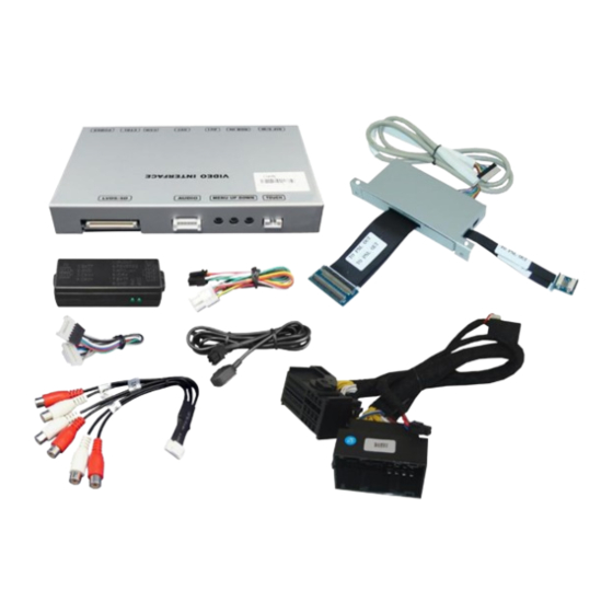
Read the manual prior to installation. Technical knowledge is necessary for installation. The place of installation must be free of moisture and away from heat sources. 1.1. Delivery contents Take down the serial number of the interface and store this manual for support purposes: ____________________ Version 04.07.2023 HW: 32 VL2-UCON8-AO... -
Page 4: Checking The Compatibility Of Vehicle And Accessories
To delay the switch-back, an additional electronic part is required. Guidelines Displayed guidelines are not available in all vehicles. Video input signal NTSC video sources compatible only. Version 04.07.2023 HW: 32 VL2-UCON8-AO... -
Page 5: Settings Of The 8 Dip Switches (Black)
RGB-input resolution 800x480 1080p H+V sync Rear-view cam type after-market factory or none No function set to OFF No function set to OFF No function Set to OFF See the following chapters for detailed information. Version 04.07.2023 HW: 32 VL2-UCON8-AO... -
Page 6: Enabling The Interface's Video Inputs (Dip 1-3)
If set to ON, the interface switches to its rear-view camera input “Camera-IN” while the reverse gear is engaged. Note: Dip 6, 7 and 8 are out of function and have to be set to OFF. Version 04.07.2023 HW: 32 VL2-UCON8-AO... -
Page 7: Installation
2.1.1. Place of installation - daugter PCB-box The daughter PCB is performed to be installed on the rearside of the head unit. The connection has to be done between the monitor panel and the head unit’s motherboard. Version 04.07.2023 HW: 32 VL2-UCON8-AO... -
Page 8: Connection Schema
2.2. Connection schema Version 04.07.2023 HW: 32 VL2-UCON8-AO... -
Page 9: Connection To The Head-Unit - Lvds
Carefully clip out the kopper coulored 60pin ribbon cable at the monitor panel’s ribbon cable base and lead it out. Note: The connected ribbon cables have to be handled with care to avoid each damage of the sensitive electrical inducters. Version 04.07.2023 HW: 32 VL2-UCON8-AO... - Page 10 After a check of the perfect ribbon cable connection, in reverse order fold back and clip in the monitor panel to the head unit housing, connect the head unit mainboard and fix it to the head unit’s rearside, before screwing on the head units frame again. Version 04.07.2023 HW: 32 VL2-UCON8-AO...
-
Page 11: Warning Notes, Concerning The Installation Of Ribbon Cables
2) The ribbon cable’s contacting side always has to correspond to the contacting side of the connector, concerning the mounting position. 3) Avoid cable contusion or cable injury caused by sharp-edged metal. Version 04.07.2023 HW: 32 VL2-UCON8-AO... -
Page 12: Connection To The Head-Unit - Quadlock
Connect the opposite female Quadlock connector of the Quadlock harness to the male Quadlock connector of the head-unit. Connect the femal 6pin connector of the Power /CAN cable to the 6pin connector of the video interface. Version 04.07.2023 HW: 32 VL2-UCON8-AO... -
Page 13: Connecting Video Sources
Connect the video RCA of the AV-source 1 to the female RCA connector “AV1” of the video interface. Connect the video RCA of the AV-source 2 to the female RCA connector “AV2” of the video interface. Version 04.07.2023 HW: 32 VL2-UCON8-AO... -
Page 14: Audio-Insertion
The inserted video-signal can be activated simultaneously to each audio-mode of the factory infotainment. The audio switching of the connected AV sources is performed by the video interface’s audio switch. 2.5.2.1. Audio connection of the AV sources AV1 and AV2 Version 04.07.2023 HW: 32 VL2-UCON8-AO... -
Page 15: After-Market Rear-View Camera
The 12 V power supply for the rear-view camera (max 3A) has to be taken from the green wire of the 20pin cable to avoid an unnecessary permanent power supply to the camera electronic. Version 04.07.2023 HW: 32 VL2-UCON8-AO... - Page 16 Additionally connect the output connector (87) of the relay to the rear-view camera’s power-cable, like you did it to the green “Reverse-IN” cable before. Connect permanent power / 12V to the relay’s input connector (30). Version 04.07.2023 HW: 32 VL2-UCON8-AO...
-
Page 17: Video Signal Connection For The Rear-View Camera
Connect the external keypad’s female 4pin connector to the video-interface’s male 4pin connector. Note: Even if the switching through several video sources by the keypad mightn’t be required, the invisible connection and availability is strongly recommended. Version 04.07.2023 HW: 32 VL2-UCON8-AO... -
Page 18: Picture Settings And Guide Lines
IR-AV1 out of function IR-AV2 out of function Guide lines (ON/OFF) Note: If the CAN-box does not support the vehicle’s CAN, the guide-lines cannot be used, even if they appeared once after connecting the system. Version 04.07.2023 HW: 32 VL2-UCON8-AO... -
Page 19: Interface Operation
Switchover by vehicle buttons isn’t possible in all vehicles. In some vehicles the external keypad has to be used. 3.2. By external keypad Alternatively or additionally to the steering wheel’s volume button, the interface’s enabled inputs are also switchable by the external keypad. Version 04.07.2023 HW: 32 VL2-UCON8-AO... -
Page 20: Specifications
0.7V with 75 Ohm impedance Temperature range -40°C to +85°C Dimensions Video-Box 159 x 22 x 98 mm (W x H x D) Dimensions Video-Box 114 x 52 x 15 mm (W x H x D) Version 04.07.2023 HW: 32 VL2-UCON8-AO... -
Page 21: Faq - Trouble Shooting Vl-2 Functions
Camera input picture fluorescent light which shines Test camera under natural light outside the garage. flickers. directly into the camera. Camera input picture is Protection sticker not Remove protection sticker from lens. bluish. removed from camera lens. Version 04.07.2023 HW: 32 VL2-UCON8-AO... -
Page 22: Technical Support
6pin to 8pin cable and isolate both ends. Technical Support Please note that direct technical support is only available for products purchased directly from NavLinkz GmbH. For products bought from other sources, contact your vendor for technical support. NavLinkz GmbH...
Need help?
Do you have a question about the VL2-UCON8-AO and is the answer not in the manual?
Questions and answers