biodex 058-840 Quick Start Manual
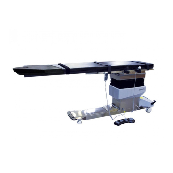
Surgical c-arm table
Hide thumbs
Also See for 058-840:
- Installation and operation manual (28 pages) ,
- Unpacking instructions and assembly (4 pages)

Related Manuals for biodex 058-840


Summary of Contents for biodex 058-840
- Page 1 SURGICAL C-ARM TABLE SERVICE MANUAL 058-840 058-845 058-840 IODEX Biodex Medical Systems, Inc. FN: 10-218 11/10...
- Page 2 SURGICAL C-ARM TABLE 058-840 This manual covers installation and operation procedures for the following product: #058-840 Table, Surgical C-Arm - 840, 115 VAC #058-845 Table, Surgical C-Arm - 840, 230 VAC — II —...
- Page 3 6. HEAD-TO-TOE TILT ACTUATOR REPLACEMENT, 058-840 7. TABLETOP REPLACEMENT, 058-840 8. CONTROLLER BOX REPLACEABLE COMPONENT PROCEDURE, 058-840 9. TILT SENSOR BOARD REMOVAL AND REPLACEMENT, 058-840 10. POSITION SENSING STRIP REPLACEMENT PROCEDURE, 058-840 11. TABLE CALIBRATION PROCEDURE, 058-840 12. OPERATION/CALIBRATION VERIFICATION, 058-840 13.
- Page 4 1. CONTROL MODULE REPLACEMENT, 058-840 Tools Required: Phillips screwdriver The control module is located on the lower back panel. To access the control module, remove the four larger Phillips screws securing the lower por- tion of the bellows to the clamshell covers. Each side has two screws located near the center of the clamshell.
- Page 5 CONTENTS Six Phillips screws securing side cover/control box Figure 1.2. The Control box is secured with six nuts Calibration port LCD display cable X, Y, tilt position sense Hand/Foot control cable Main power coiled cable for X and Y, roll actuator Trendelenburg actuator Figure 1.3.
- Page 6 2. X MOVEMENT SOLENOID REPLACEMENT, 058-840 (HEAD-TO-TOE) Tools Required: Allen keys Wire cutters Socket set, standard Phillips screwdriver REMOVAL Make sure the table is level before removing the solenoid assembly. The table may abruptly move when the solenoid assembly is disconnected.
- Page 7 CONTENTS Figure 2.1. Figure 2.2. X MOVEMENT SOLENOID REPLACEMENT — 4 —...
- Page 8 3. Y MOVEMENT SOLENOID REPLACEMENT, 058-840 (LATERAL) X-MECHLOCK (058-840-A040) AND Y-MECHLOCK (058-840-A030) REPLACEMENT AND CLEANING Model 058-840 Series Tables Tools Required: Medium Phillips screwdriver 9/16-inch Wrench 3/8-inch Wrench 1/2-inch Wrench 7/16-inch Wrench 5/32-inch Allen Key 3/16-inch Allen Key Wire Cutter C13349 Lubrication for Piston Level and raise the tabletop to position 10 (the highest point).
- Page 9 CONTENTS Underneath Head End of Table Remove four -inch 9/16 bolts w/Washers b. Move the tabletop all the way to position 20 (foot end of the table) to access the four bolts. Underneath Foot End of Table Remove two -inch 9/16 bolts w/o washers...
- Page 10 CONTENTS To change out the X-Mechlock unplug the wire harness connector. Remove the 5/32-inch bolts and washers with a 5/32-inch Allen Key. They are located on the outside of the foot end of the table by the handle. Remove two -inch 5/32 Allen Head Bolts...
- Page 11 CONTENTS You should now be able to remove the broken X-Mechlock and replace it with the new one. After you have put the bolts back into place reconnect the Mechlock. Turn on the power and test for correct operation. (You shouldn’t have to recalibrate the table for the X direction because the pot that measures the location was not removed from the table.) 10.
- Page 12 CONTENTS 12. Remove the 3/16-inch Allen Head Bolt that holds the solenoid to the bracket. Remove -inch 3/16 Allen Head Bolt 13. Loosen the 3/16-inch hex nut on the other side. You will have to use a short length Allen key to reach the nut.
- Page 13 CONTENTS 15. To clean the piston on a Mechlock you must use either a contact cleaner or alcohol. Shoot the solenoid a couple times after you apply the cleaner. This will help get any dirt inside the solenoid. After you have the solenoid completely cleaned apply the C13349 Lubrication to the piston and again shoot the piston.
- Page 14 4. LIFT ACTUATOR REPLACEMENT, 058-840 Tools Required Phillips screwdriver 5 mm Allen key 8 mm wrench PROCEDURE If the lift actuator is operational, the table should be brought down to its lowest position. If the actuator is not operational, the tabletop must be supported to prevent it from falling once the actuator is removed.
- Page 15 CONTENTS Lift actuator lower bolt and nut Figure 4.1 Lift actuator upper bolt and nut Figure 4.2. Control box is secured with six nuts Calibration port LCD display cable X, Y, tilt position sense Hand/Foot control cable Main power coiled cable for X and Y, roll actuator Trendelenburg actuator Figure 4.3.
- Page 16 5. LATERAL TILT ACTUATOR REPLACEMENT, 058-840 PROCEDURE If the lateral tilt actuator is operational, tilt it down on the patient right side. The table should be brought head down to its lowest position. If the actuator is not operational, the tabletop must be supported to prevent the tabletop from suddenly tilting once the actuator is removed.
- Page 17 CONTENTS Securing bolt and nut. Figure 5.1 3/16" Allen head bolts Figure 5.2. The control box is secured with six nuts Calibration port LCD display cable X, Y, tilt position sense Hand/Foot control cable Main power coiled cable for X and Y, roll actuator Trendelenburg actuator...
- Page 18 6. HEAD-TO-TOE TILT ACTUATOR REPLACEMENT, 058-840 PROCEDURE If the tilt actuator is operational, the table should be brought head down to its lowest posi- tion. If the actuator is not operational, the tabletop must be supported to prevent the top from suddenly tilting once the actuator is removed.
- Page 19 CONTENTS Actuator lower securing pin and clip Figure 6.1. Actuator upper securing pin and clip Figure 6.2. Trendelenburg actuator Figure 6.3. HEAD-TO-TOE TILT ACTUATOR REPLACEMENT — 16 —...
- Page 20 7. TABLETOP REPLACEMENT, 058-840 Activate the X motor and move the tabletop all the way towards the back. Remove the four 9/16-inch bolts, which are now accessible from the underside of the table- top (see Figure 9.1). Activate the X motor and move the tabletop all the way forward.
-
Page 21: Replaceable Components
8. CONTROLLER BOX REPLACEABLE COMPONENT PROCEDURE, 058-840 H-bridge motor controller boards 5v logic supply fuse Fowler back 24v Power supply fuses for motors Power supply board UP/Down Pitch Figure 8.1. Front/Back Roll Side to Side Figure 8.1 shows the control board layout. There are six board slots, which are labeled to desig- nate their function. - Page 22 9. TILT SENSOR BOARD REMOVAL AND REPLACEMENT, 058-840 Connector Tilt Sensor Board Figure 9.1. PROCEDURE The tilt sensor is under the tabletop, on the patient left side next to lateral tilt actuator. Raise table to maximum height, for better accessibility.
- Page 23 10. POSITION SENSING STRIP REPLACEMENT, PROCEDURE 058-840 PROCEDURE The table utilizes three precision resistor strips to sense the table’s height and X, Y tabletop posi- tion. Figure 10.1 shows the resistor strip installed on the table. The wiper/roller move along the resistor strip as the position of the table changes.
- Page 24 CONTENTS Resistor strip wiper Y position resister strip Y-motor Wiper bracket securing screws Figure 10.3. Y position sensing resistor strip (actuator assembly, tabletop removed) Resistor strip Resistor wipes Figure 10.4. X position sensing resistor strip (tabletop removed for viewing) Figure 10.5. Resistor strip not installed. Note that the strip is secured with adhesive to a thin metal mounting plate.
- Page 25 CONTENTS REPLACING THE RESISTOR STRIP To replace the resistor strip, remove the two securing screws. Next, lift wiper/roller and remove the strip (strip may also be secured with adhesive). When any sensor is replaced a table calibra- tion is required. Refer to Chapter 11, Calibration Procedure, for instructions. —...
- Page 26 11. TABLE CALIBRATION PROCEDURE, 058-840 Required Equipment PC with latest table calibration software installed PROCEDURE Connect COMM PORT 1 of the PC to the 9 pin male "D" connector of the table’s control box, using a 9 pin female to 9 pin female RS-232 cable.
- Page 27 CONTENTS 14. Calibrate FORWARD/BACK: Use Release Handle so that "+ +" is displayed in the utility's receive window. b. When the MAX Position is reached, reverse direction momentarily to back away from the MAX Position slightly, then press any key to set position. Use Release Handle to move tabletop so that "- -"...
- Page 28 12. OPERATION/CALIBRATION VERIFICATION, 058-840 PROCEDURE AC Powered MAIN LCD CONTROL Verify scaling on all axes. Pitch -1 to –20, 0, 1 to 20 b. Roll R1-20, 0, L1-20 Vertical 0 - 10 Verify that the commanded direction matches the actual direction for all axes.
- Page 29 CONTENTS FOOTSWITCH CONTROL Verify scaling on all axes. Pitch -1 to –20, 0, 1 to 20 b. Roll R1-20, 0, L1-20 Vertical 0 - 10 Verify that the commanded direction matches the actual direction for all axes. Verify that the footswitch operates in both ports. BATTERY Powered MAIN LCD CONTROL Verify scaling on all axes.
- Page 30 13. DISPLAY LCD PENDANT REPLACEMENT, 058-840 HAND PENDANT CONTROL Verify scaling on all axes. Pitch -1 to –20, 0, 1 to 20 b. Roll R1-20, 0, L1-20 Vertical 0 - 10 Verify that the commanded direction matches the actual direction for all axes.
-
Page 31: Removal Of Display
CONTENTS The LCD Pendant displays and stores position information and controls all the motor move- ments, up/down, Trendelenburg /rev, lateral roll, head to toe actuator (X) and side-to-side actu- ator (Y). The Release Handle releases the X and Y solenoids simultaneously, which allows the top to float. - Page 32 14. TABLE FIRMWARE UPDATE, 058-840 Connect the PC to the 9 pin female "D" connector of the control box, using the special 9 pin female to 9 pin male DSP programming cable. Turn the computer and monitor on. Turn the table on.
- Page 33 15. PART AND ASSEMBLY ILLUSTRATIONS, 058-840 — 35 — 058-840 PART AND ASSEMBLY ILLUSTRATIONS...
- Page 34 058-840 PART AND ASSEMBLY ILLUSTRATIONS — 36 —...
- Page 35 — 37 — 058-840 PART AND ASSEMBLY ILLUSTRATIONS...
- Page 36 058-840 PART AND ASSEMBLY ILLUSTRATIONS — 38 —...
- Page 37 — 39 — 058-840 PART AND ASSEMBLY ILLUSTRATIONS...
- Page 38 058-840 PART AND ASSEMBLY ILLUSTRATIONS — 40 —...
- Page 39 — 41 — 058-840 PART AND ASSEMBLY ILLUSTRATIONS...
- Page 40 058-840 PART AND ASSEMBLY ILLUSTRATIONS — 42 —...
- Page 41 — 43 — 058-840 PART AND ASSEMBLY ILLUSTRATIONS...
- Page 42 058-840 PART AND ASSEMBLY ILLUSTRATIONS — 44 —...
- Page 43 — 45 — 058-840 PART AND ASSEMBLY ILLUSTRATIONS...
- Page 44 058-840 PART AND ASSEMBLY ILLUSTRATIONS — 46 —...
- Page 45 — 47 — 058-840 PART AND ASSEMBLY ILLUSTRATIONS...
- Page 46 058-840 PART AND ASSEMBLY ILLUSTRATIONS — 48 —...
- Page 47 — 49 — 058-840 PART AND ASSEMBLY ILLUSTRATIONS...
- Page 48 058-840 PART AND ASSEMBLY ILLUSTRATIONS — 50 —...
- Page 49 — 51 — 058-840 PART AND ASSEMBLY ILLUSTRATIONS...
- Page 50 058-840 PART AND ASSEMBLY ILLUSTRATIONS — 52 —...
- Page 51 — 53 — 058-840 PART AND ASSEMBLY ILLUSTRATIONS...
- Page 52 058-840 PART AND ASSEMBLY ILLUSTRATIONS — 54 —...
- Page 53 NOTES — 55 — NOTES...
- Page 54 Certified Quality Management System IODEX Biodex Medical Systems, Inc.
Need help?
Do you have a question about the 058-840 and is the answer not in the manual?
Questions and answers