Table of Contents
Advertisement
Quick Links
Advertisement
Table of Contents

Related Manuals for Maxtang BYT-60


Summary of Contents for Maxtang BYT-60
- Page 1 BYT-60 Mini ITX Motherboard...
- Page 2 Copyright © 2022 Shenzhen Maxtang Computer Co., Ltd. All rights reserved. No part of this publication may be reproduced, copied, stored in a retrieval system, translated into any language, or transmitted in any form or by any means, electronic, mechanical, photocopying, or otherwise, without the prior written consent of Shenzhen Maxtang Computer Co., Ltd (hereinafter referred to as “Maxtang”).
-
Page 3: Byt-60 Mini Itx Motherboard
Shenzhen Maxtang Computer Co., Ltd BYT-60 Mini ITX Motherboard User Manual (Version 5.1) -
Page 4: Table Of Contents
Shenzhen Maxtang Computer Co., Ltd Contents BYT-60 Mini ITX Motherboard ......................1 Chapter 1 Product Introduction ...................... 3 1.1 Parameters ..........................3 Chapter 2 Hardware ........................4 2.1 Connector Diagram ........................4 2.2 Jumper Setting .......................... 5 2.3 Memory Slots ..........................5 2.4 Internal Display Interface (JHDMI, JVGA) ................. -
Page 5: Chapter 1 Product Introduction
Shenzhen Maxtang Computer Co., Ltd Chapter 1 Product Introduction 1.1 Parameters Processor: Intel Bay Trail-D Celeron J1900(2.0GHz, quad-core, TDP10W) Intel Bay Trail-D Celeron J1800(2.41GHz, dual-core, TDP10W) Intel Bay Trail-D Atom-E3845(1.91GHz, quad-core, TDP10W) Memory: 1x Single Channel DDR3L 1333MHz slot, up to 8GB... -
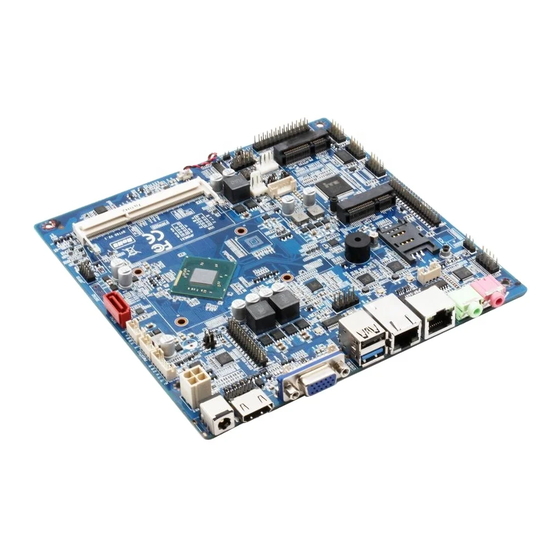
Page 6: Chapter 2 Hardware
Shenzhen Maxtang Computer Co., Ltd Chapter 2 Hardware 2.1 Connector Diagram F-AUDIO JHDMI USB2.0 Speaker SIM CARD PS/2 COM2 eDP/LVDS Mini-PCIE LVDS_ADJ COM3-6 GPIO mSATA DIMM USB2.0 BKLADJ_C JPOWER PSATA COM1 CLR_CMOS SATA2.0 Please read the user manual carefully, before you connect to an external connector, in case of board damage. -
Page 7: Jumper Setting
Shenzhen Maxtang Computer Co., Ltd 2.2 Jumper Setting Please configure the jumpers according to your needs before installing the hardware. How to identify the first header of jumpers and pins: Observe the mark beside the jumper or pins and find the header marked by “1”... - Page 8 Shenzhen Maxtang Computer Co., Ltd LVDS data pin (screen printing: EDP/LVDS) Signal Signal A_DATA0_DN A_DATA0_DP A_DATA1_DN A_DATA1_DP A_DATA2_DN A_DATA2_DP A_CLK_DN A_CLK_DP A_DATA3_DN A_DATA3_DP B_DATA0_DN B_DATA0_DP B_DATA1_DN B_DATA1_DP B_DATA2_DN B_DATA2_DP B_CLK_DN B_CLK_DP B_DATA3_DN B_DATA3_DP LVDS backlight (screen printing: LVDS_ADJ) Signal LCD_BKL_ADJ...
-
Page 9: Edp (Optional)
Shenzhen Maxtang Computer Co., Ltd LVDS screen voltage jumper (screen printing: J3) Setting Function Close VCC(+3.3V) Close VCC(+5V) Close VCC(+12V) Note: The LVDS display power supply can be adjusted among 12V/5V/3.3V via jumper setting. Users can connect the VCC with a jumper cap by 2pin according to their LVDS screen’s voltage (Short-circuiting two or more interfaces via jumper cap at the same time is strictly forbidden). -
Page 10: Internal Pwr2
Shenzhen Maxtang Computer Co., Ltd eDP voltage pin (Screen printing: J3) Interface Settings Function Close VCC(+3.3V) Close VCC(+5V) Close VCC(+12V) Note: The eDP display power is controlled by jumpers. The voltage can be adjusted between 12V/5V/3.3V. Don't short-circuit two or more interfaces with a jumper cap. -
Page 11: Audio (Fp_Audio, Jaud, Jspif)
Shenzhen Maxtang Computer Co., Ltd RJ45 LAN LED Description: LILED (Orange)Status Function ACTLED (Green) Status Function Always on Connected Blink Data transmission 2.10 Audio (FP_AUDIO, JAUD, JSPIF) Features the ALC662 audio codec, the green interface is Speaker-out and the pink interface is Mic-in; the JAUD is amplifier output;... -
Page 12: Com (Jcom1, Jcom2, Jcom36, Jcom2/4_P)
Shenzhen Maxtang Computer Co., Ltd 2.11 COM (JCOM1, JCOM2, JCOM36, JCOM2/4_P) Supports 6 x RS232, and COM6 can be set as RS485. COM1 and COM2 are industrial definitions. COM2 and COM4 come with power and can set up a different voltage through jumper COM2/4_P. - Page 13 Shenzhen Maxtang Computer Co., Ltd Signal Signal RI#_3 (NC) DCD#_4 RXD_4 TXD_4 DTR#_4 DSR#_4 RTS#_4 CTS#_4 (NC) / VCC(5V/12V) (NC) DCD#_5 RXD_5 TXD_5 DTR#_5 DSR#_5 RTS#_5 CTS#_5 RI#_5 (NC) DCD#_6 RXD_6 TXD_6 DTR#_6 DSR#_6 RTS#_6 CTS#_6 RI#_6 (NC) When COM6 is set as RS232 and RS485, the header definition is as follows:...
-
Page 14: Lpt (Jlpt, J4)
Shenzhen Maxtang Computer Co., Ltd 2.12 LPT (JLPT, J4) The board provides a set of 2x13pin LPT header (space in between: 2.0mm). Users can use it to connect to other equipment like a printer. Users need to disable the LPT function in the BIOS to set the LPT as 16 lanes GIPO. -
Page 15: Gpio
Shenzhen Maxtang Computer Co., Ltd GPIO_76 GPIO_77 GPIO_83 GPIO_82 GPIO_81 GPIO_80 (NC) J4 (Voltage setting): Function Setting GPIO short-circuit 1-2 Printing short-circuit 2-3 Do not short-circuit three sets of pins same time in case of board damages. 2.13 GPIO(JGPIO) A set of 2×5Pin (connected from CPU) JGPI0 header, 8 programmable I/O interfaces in total. -
Page 16: Mini-Pcie (Mini-Pcie, Sim1)
Shenzhen Maxtang Computer Co., Ltd +12V 2.15 Mini-PCIe (Mini-PCIe, SIM1) Supports Wi-Fi card with standard SIM card slot for 3G/4G module expansions. 2.16 PS/2 (PS2) The board offers a 6Pin PS/2 socket. Signal KB_DATA KB_CLK MS_ DATA MS_CLK 2.17 CPU FAN (CPU_FAN1) The board offers a 4Pin CPU smart fan socket. -
Page 17: Front Panel Control Interface (Jpower1)
Shenzhen Maxtang Computer Co., Ltd 2.19 Front Panel Control Interface (JPOWER1) The front panel control interface is intended to connect the function buttons and the light indicator on the front panel. JPOWER1: Signal Signal HDD_LED+ PWR_LED+ HDD_LED- PWR_LED- RST_BTN- PWR_ON+...
Need help?
Do you have a question about the BYT-60 and is the answer not in the manual?
Questions and answers