Table of Contents
Advertisement
Quick Links
Advertisement
Table of Contents

Related Manuals for Maxtang DTJ6412-A


Summary of Contents for Maxtang DTJ6412-A
- Page 1 DTJ6412-A Mini-ITX Motherboard User Manual...
-
Page 2: Table Of Contents
Contents Chapter 1 Product Introduction ......................3 Brief Introduction ......................3 Parameters ........................3 Connector Diagram ......................4 Chapter 2 Hardware ................6 Installations ........................6 Jumper Setting ........................6 Memory Slots ........................6 Display Interfaces ......................7 Storage ............................9 Expansion Slot ..........................9 USB Interface ..........................9 LAN ...............................9 COM .............................9 LPT 11 GPIO ............................ -
Page 3: Chapter 1 Product Introduction
Chapter 1 Product Introduction Brief Introduction The EHL-10 is a mini ITX motherboard based on the Intel Elkhart Lake platform; features a small form factor, low power consumption, and high performance. Parameters CPU: Intel Celeron J6412——4Cores 4Threads, Base Frequency 2.00GHz, Burst Frequency 2.60 GHz, TDP 10W Intel Pentium J6426——4Cores 4Threads, Base Frequency 2.00GHz, Burst Frequency 3.00 GHz, TDP 10W Intel Atom x6425RE——4Cores 4Threads, Base Frequency 1.9GHz, TDP 12W Intel Atom x6427FE——4Cores 4Threads, Base Frequency 1.9GHz, TDP 12W... -
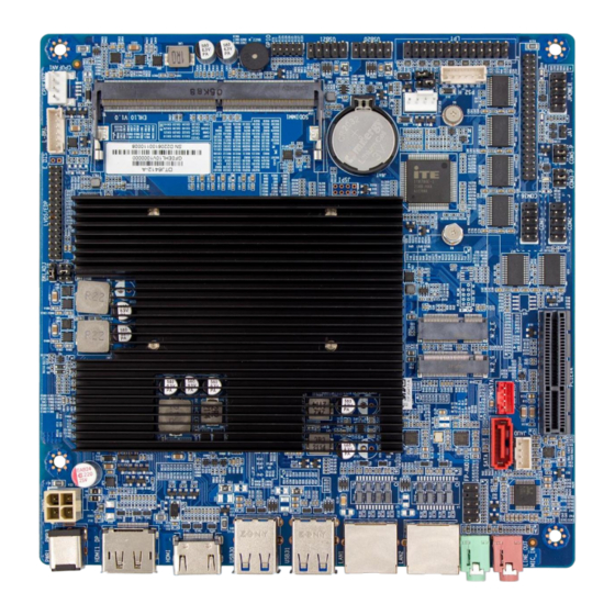
Page 4: Connector Diagram
Connector Diagram HDMI DP/HDMI 2*USB3.2 2*USB3.2 LAN23 LAN1 LINE_OUT MIC_IN DC_IN FP-AUDIO PWR2 SATA JAUD PWSATA M.2_S L-VCC PCIEX4 M.2_E BKLADJ COM2 JSPI LVDS/EDP COM1 SO-DIMM E_DIS SYSFAN JSYSFAN L-BKL JPOWER GPIO COM36 CPUFAN2 PS2_H 2*USB2.0 2*USB2.0 CPUFAN1... -
Page 6: Chapter 2 Hardware
Chapter 2 Hardware Installations Please refer to the following steps for installations: Read the user manual carefully to make sure all the adjustments on the EHL10 are correct. Installing the Memory: Press the ejector tab of the memory slot outwards with your fingertips. ... -
Page 7: Display Interfaces
Display Interfaces The board features Integrated Intel UHD graphics through 1xHDMI2.0 standard interface, 1xDP1.4(optional HDMI), 1xLVDS (optional eDP) for trio 4K displays. LVDS The board supports a dual channel 24bit LVDS interface, the "L_VCC" pin is the display working voltage adjustment jumper, and the "... - Page 8 Backlight Standard/Reverse adjustment jumper (Screen Printing: BKLADJ) Setting Function Close REV (Backlight Control Reverse) Close STD (Backlight Control Standard) eDP (Optional) Optional function, the board supports 2LANE eDP1.3 interface. When it is set as eDP functions, the pin transmits the eDP signal and disables the LVDS function. The screen power supply controls by the “L_VCC” jumper, the “L_BKL”...
-
Page 9: Storage
Close VCC 5V Close VCC 12V Backlight Standard/Reverse adjustment jumper (Screen Printing: BKADJ) Setting Function Close REV (Backlight Control Reverse) Close STD (Backlight Control Standard) Storage The board features 1x SATA3.0 standard interface, transmission rate at 6GB/s, a disk power supply socket; 1 x M.2 Key B slot for 2242/2280 SATA SSD. - Page 10 COM1, COM2 pin definition (Screen Printing: COM1, COM2) Signal Signal DCD# DTR# DSR# RTS# CTS# (NC) COM36 (Screen: COM36) Signal Signal DCD# DTR# DSR# RTS# CTS# (NC) DCD# DTR# DSR# RTS# CTS# (NC) DCD# DTR# DSR# RTS# CTS# (NC) DCD# DTR# DSR# RTS#...
-
Page 11: Lpt
DSR# (NC) RTS# (NC) CTS# (NC) (NC) A set of 2x13 Pin LPT interfaces onboard. Please use an adapter to convert the LPT interface to a standard parallel port for use. Users can connect it to a printer or other devices according to the needs. LPT (Screen Printing: LPT) Signal Signal... -
Page 12: Panel Switch Pin
PWR3: ATX12V supplementary power supply socket (2x2PIN) Panel Switch Pin The front control panel interfaces are to connect the functional buttons and indicators on the front panel. JPOWER (Screen Printing: JPOWER) Signal Signal HDD_LED+ PWR_LED+ HDD_LED- PWR_LED- RSTBTN- PWR_ON+ RSTBTN+ PWR_ON- (NC) PS/2 Socket... -
Page 13: Cpu Fan Socket
CPU FAN Socket The board provides a CPU Fan socket for cooling. The default power supply is 5V, 12V optional. CPU_FAN (Screen Printing: CPU_FAN) Signal System Fan Socket The board provides one system fan socket, default 5V for power supply (optional 12V through JSYSFAN). SYSFAN (Screen Printing: SYSFAN) Signal System Fan Voltage Setting (Screen Printing: JSYSFAN)
Need help?
Do you have a question about the DTJ6412-A and is the answer not in the manual?
Questions and answers