Advertisement
Quick Links
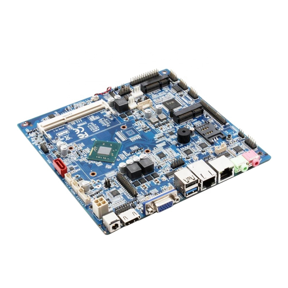
BYT60 Motherboard User's Manual Version 2.0
1.1 Motherboard Specification
Platform: Onboard Intel BayTrail-D Celeron Processor J1800, Core Frequency 2.41Ghz,
power consumption 10W
Onboard Intel Bay Trail-D Celeron Processor J1900, Core Frequency 2.00Ghz,
power consumption 10W
Memory: Single Channel DDR3L 1333Mhz, Up to 8GB system memory
Graphic: Integrated graphic processor - Intel HD graphic support
Storage: 2X SATA2.0, 1X mSATA via mini PCIe slot, SATA2 and mSATA either one, 1X
eMMC(optional)
USB: Maximum 8X USB ports with 1x USB3.0 included.
Display: 1x HDMI, 1x VGA, 1x dual-channel 24bit LVDS and dual display support
Ethernet: Onboard 2x Gigabyte internet controller RTL8111F, 1x RJ45 and 2x USB2.0
co-layout
Sound: Onboard integrated HD audio chipset ALC662 supports Speaker-out, MIC-in and
S/PDIF and amplifier
I/O: IT8786E support 6x serial COM, 1x LPT, COM2 can do eitherRS232 or RS485. IT8772E
support COM1 only.
Other I/O: 2x mini PCIe slots with either 1x mSATA and 1 slot for wifi, 3G/4G or 2x Mini
PCie/USB slots support WIFI plus 3G/4G module.
1x LPT; GPIO and 1x PS/2 for keyboard and mouse
Form Factor: 170mm x 170mm
Power supply: DC-IN 12V Power, and 1x 4pin ATX
Chapter 1 Product Introduction
1
Advertisement

Related Manuals for Maxtang BYT60


Summary of Contents for Maxtang BYT60
-
Page 1: Chapter 1 Product Introduction
BYT60 Motherboard User’s Manual Version 2.0 Chapter 1 Product Introduction 1.1 Motherboard Specification Platform: Onboard Intel BayTrail-D Celeron Processor J1800, Core Frequency 2.41Ghz, power consumption 10W Onboard Intel Bay Trail-D Celeron Processor J1900, Core Frequency 2.00Ghz, power consumption 10W Memory: Single Channel DDR3L 1333Mhz, Up to 8GB system memory Graphic: Integrated graphic processor - Intel HD graphic support Storage: 2X SATA2.0, 1X mSATA via mini PCIe slot, SATA2 and mSATA either one, 1X... -
Page 2: Chapter 2 Hardware Function
BYT60 Motherboard User’s Manual Version 1.3 Chapter 2 Hardware Function 2.1 Board Placement F-AUDIO Speaker JHDMI USB2.0 LVDS_ADJ LVDS EdDP COM3-6 SIM CARD 2*PWSATA Mini-PCIE 2*SATA PS/2 eMMC 2*COM mSATA DIMM JGPIO USB2.0 JPOWER Please take care to connect external devices for as not to damage the board! CLR_MOS 2.1.1 Jumper Function Setting... - Page 3 BYT60 Motherboard User’s Manual Version 1.3 shows 1 white arrow sign 2.1.2 Memory Slot Onboard 1x DDR3L 1333MHz SO-DIMM memory slot, memory capacity up to 8GB 2.1.3 Internal display Header (JHDMI, JVGA) One 14pin JHDMI and one 12 pin JVGA pin JHDMI:...
- Page 4 BYT60 Motherboard User’s Manual Version 1.3 2.1.4 Internal Power Supply (PWR2) Pin No Definition +12V +12V 2.1.5 Internal USB pin (USB1, USB2) Onboard USB header for USB2.0 port USB1、USB2: Definition Pin No. Definition USB DATA- USB DATA- USB DATA+ USB DATA+ 2.1.6 LAN...
- Page 5 BYT60 Motherboard User’s Manual Version 1.3 2.1.7(FP_AUDIO, JAUD,JSPIF)Audio Header Realtek ALC662 audio controller chipset, Green is the audio output port (Speaker-Out), Pink is MIC-in audio input port; JAUD is audio amplifier and JSPIF is fiber digital audio signal. FP_AUDIO: Front Panel Audio (FP-Audio)
- Page 6 BYT60 Motherboard User’s Manual Version 1.3 2.1.8 LVDS ( JLVDS,LVDS_ADJ & J2 ) Dual-channel 24bit LVDS header, VCC of LVDS power cable supply can be choose by J2 control, LVDS_ADJ use for LVDS back-light power control. JLVDS1: Definition Pin No...
- Page 7 BYT60 Motherboard User’s Manual Version 1.3 J2:LVDS Power Pin No Setting Function Close VCC(+3.3V) Close VCC(+5V) Close VCC(+12V) Attention: You can choose 12V/5V/3.3V between the three flexible adjustments. Customer according to the LVDS voltage specification, use the jumper cap to meet the...
- Page 8 BYT60 Motherboard User’s Manual Version 1.3 LCD_BKL_ON LCD_BKL_ADJ eDP Power(丝印:J2): Close VCC(+3.3V) Close VCC(+5V) Close VCC(+12V) Serial COM(JCOM1 ,JCOM2,JCOM36,JCOM2_P,JCOM4_P) Provides 6x COM supports RS232. COM1 and COM2 defines as industrial definition; JCOM2 and JCOM4 provides 5V/12V by jumper. JCOM1: Definition...
- Page 9 BYT60 Motherboard User’s Manual Version 1.3 Definition Pin No Definition DCD# DTR# DSR# RTS# CTS# DCD# DTR# DSR# RTS# CTS# DCD# DTR# DSR# RTS# CTS# DCD# DTR# DSR# RTS# CTS# JCOM2 ; JCOM4: PIN No Setting Function Close Close Close 2.1.10 Parallel Port (LPT)
- Page 10 BYT60 Motherboard User’s Manual Version 1.3 LPT: Definition Pin No Definition LPT_ PPD0 ERROR LPT_ PPD1 INIT LPT_ PPD2 SLIN LPT_ PPD3 LPT_ PPD4 LPT_ PPD5 LPT_ PPD6 LPT_ PPD7 BUSY SLCT 2.1.11 JGPIO 4 input and 4 Output Definition...
- Page 11 BYT60 Motherboard User’s Manual Version 1.3 +12V 2.1.13 eMMC (Optional) eMMC support UEFI operation system such as Windows 10 64bit, Windows 8 64bit and Linux 64bit. 2.1.14(MINI-PCIE,SIM1)Mini-PCIe One mini PCI-e slot support WIFI module or 3G/4G Module with 1x SIM card slot.
- Page 12 BYT60 Motherboard User’s Manual Version 1.3 2.1.18 CMOS Clear / Default as Setting CMOS powered by the onboard button cell battery, clearing CMOS will lead to the permanent elimination of system setup (Default as factory setting) Steps: Turn off your computer, disconnect the power supply Use a jumper CAP shorts circuit function on JCOMS socket, holds for 3 to 5 seconds, then disconnect.
Need help?
Do you have a question about the BYT60 and is the answer not in the manual?
Questions and answers