
Related Manuals for Hydrotechnik MultiControl 4070


Summary of Contents for Hydrotechnik MultiControl 4070
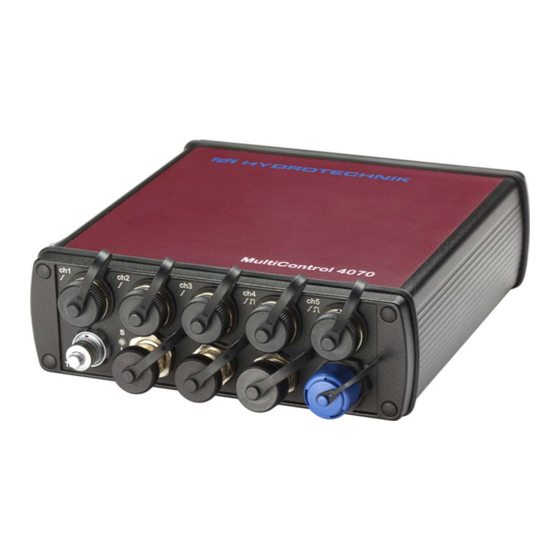
- Page 1 MultiControl 4070 Universal Portable Measuring System Operating Instructions Firmware Version 1.2 Manual Version 1.0...
-
Page 2: Table Of Contents
Internal data memory........32 Description of the measuring instru- DATA-VOL partition directories ....33 ment Reset device ............. 35 Properties of the MultiControl 4070 ....10 Cleaning and maintenance Connections ............11 Cleaning............36 Analog inputs ..........12 Maintenance ............. 37 Frequency/analog inputs...... -
Page 3: General Safety And Warning Information
Safety Safety The following safety notices for MultiControl 4070 are grouped by topic. Read the safety notices before commissioning the instrument. General safety and warning information • Never cut, damage or modify the connecting cables for the power pack. •... -
Page 4: Handling Information For The Multicontrol 4070
Safety Handling information for the MultiControl 4070 • Never expose the instrument to excessive heat, cold, or humidity. Technical data on page 22 • Do not store the instrument in a humid or dusty location. • Never submerge the instrument into water or other liquids. Never let liquids come into the instrument. -
Page 5: Information About Handling Batteries
Never disassemble, repair or modify the batteries. • Never short-circuit the contacts of batteries. • Use only batteries that are installed or delivered by HYDROTECHNIK. • Only charge the battery while it is mounted in the instrument. • Charge the battery for 3 hours before you commission the instrument. The battery will be charged as soon as the instrument is supplied by a HYDROTECHNIK power pack. -
Page 6: Introduction
Scope The manual on hand is valid for measuring instruments named MultiControl 4070. It is intended for operators of the instrument, i.e. persons who work with the instrument. This is not a technical manual. Please contact our customer service for questions that go beyond the contents of this manual. -
Page 7: Limitation Of Liability
HYDROTECHNIK. The products of HYDROTECHNIK GmbH are designed for a long life. They re- present the state of the art and their functions have been individually checked before delivery. -
Page 8: Intended Use
Introduction Intended use The MultiControl 4070 instrument is a portable measuring system for the re- cording and storage of measurement data from sensors connected to the measuring instrument. The measurement data can then be read and evalua- ted using the HYDROcom6 software. -
Page 9: Customer Obligations
Persons who operate this instrument must • obey all regulations on occupational safety and accident prevention • have read and understood the MultiControl 4070 operating instructions in full, especially the safety instructions Safety on page 3. • have read and understood the HYDROlink6 software operating instructi- ons in full •... -
Page 10: Description Of The Measuring Instrument
HYDROlink6 software. The software is in- cluded in the scope of delivery and is used to configure and control MultiControl 4070. The software operating instructions can be found in the download area of our website at www.hydrotechnik.com. -
Page 11: Connections
LED (L) for Ethernet connection status Analog input ch3 Ethernet connection Frequency/analog input ch4 Combi jack CAN / RS232 Frequency/analog input ch5 Combi jack CAN / Power Digital input/output trigger signal USB-C interface Picture 5-1: Back of MultiControl 4070 Firmware Version 1.2 MultiControl 4070... -
Page 12: Analog Inputs
5 V (DC) Transil diode Ground 100 mA Current limiting Signal U [V] 88 kΩ 4.7 nF ±15 V (DC) Transil diode Shield ISDS Table: Pin assignment for analog inputs Power supply during mains operation 15 V Firmware Version 1.2 MultiControl 4070... -
Page 13: Frequency/Analog Inputs
VDR Transile diode Ground 100 mA Signal direction 100 kΩ 33 nF 15 V (DC) VDR Transile diode Shield ISDS Table: Pin assignment for frequency/analog inputs in frequency mode Power supply during mains operation 15 V Firmware Version 1.2 MultiControl 4070... - Page 14 Ground 100 mA Current limiting Signal U [V] 8.8 kΩ 100 nF ±15 V (DC) Transil diode Shield ISDS Table: Pin assignment for frequency/analog inputs in analog mode Power supply during mains operation 15 V Firmware Version 1.2 MultiControl 4070...
-
Page 15: Digital Signal Input
The digital signal output is connected to the jacks (pins 1 and 2) of the digital input/output (trigger). Function Limitation Protection type Ground Signal Ub/10 mA VDR Transile diode Table: Pin assignment for digital signal output Firmware Version 1.2 MultiControl 4070... -
Page 16: Ethernet Connection
Reserved for bootloader CAN L CAN Low RS232 signal RXD Table: Pin assignment for combi jack CAN / RS 232 ~14.6 to 15 V, max. 800 mA (power supply) / ~13 V (DC), 180 mA (battery) Firmware Version 1.2 MultiControl 4070... -
Page 17: Combi Jack Can / Power
CAN Low Table: Pin assignment for combi jack CAN / Power USB-C interface The USB-C interface facilitates communication with a PC/laptop. HYDROTECHNIK recommends this connection for commissioning and confi- guring the sensors with the HYDROlink6 software. Firmware Version 1.2 MultiControl 4070... -
Page 18: Led Status Indicators
Description of the measuring instru- LED status indicators ON/OFF button status indicator ON/OFF button Picture 5-2: Front of MultiControl 4070 The illuminated ON/OFF button on the front of MultiControl 4070 displays the following instrument statuses: LED code Status Description Operation The instrument is ready for opera- tion. -
Page 19: Status Indicator On The Back Of Instrument - Led (S)
LED is off and flashes 10 times every 1.5 seconds brated. Error code 11 No battery detected. LED is off and flashes 11 times every 1.5 seconds Table: Status indicator on the back of instrument – LED (S) Firmware Version 1.2 MultiControl 4070... -
Page 20: Status Indicator On The Back Of Instrument - Led (L)
Description of the measuring instru- Status indicator on the back of instrument – LED (L) The bottom LED (L) on the back of MultiControl 4070 indicates the status of the Ethernet connection. The following statuses are possible. LED code Description LED flashes orange Ethernet connection detected. -
Page 21: Software
HYDROlink6 and HYDROcom6 software. The HYDROTECHNIK customer center is in the download area of our website at www.hydrotechnik.com. It informs you automatically of firmware updates and requests that you install these updates. -
Page 22: Technical Data
Frequency inputs 0.25 Hz … 20 kHz Measured value memory 4 GB SD card, max. 100 measurement series, max. 8 MB per measurement series (2 million values) Tolerances Analog ±0.1% of final value Digital ±0.02% from measurement value (resolution: 20 ns) Firmware Version 1.2 MultiControl 4070... -
Page 23: Commissioning
To maintain all claims against the shipping company you should document all possible transportation damage (e.g. by taking photos and signing a written protocol), before you unpack the measuring instrument. HYDROTECHNIK is not responsible for transportation damage and will assu- me no liability. Firmware Version 1.2... -
Page 24: Check The Scope Of Delivery
• Serial number key for HYDROlink6 Advanced software Check the scope of delivery against the delivery note and the order docu- ments. Please report any discrepancies immediately to HYDROTECHNIK. Subsequent claims about incomplete delivery cannot be accepted. Charge batteries Note... -
Page 25: Display Operating Instructions
Commissioning Display operating instructions The operating instructions are available in PDF format in the download area of our website at www.hydrotechnik.com and on the measuring instrument. Displaying the operating instructions on the measuring instrument 1 Switch on the measuring instrument and PC/laptop. -
Page 26: Operation
Reset device The HYDROlink6 and HYDROcom6 software, which are needed for some of these operations, are not described here. For more information, consult the separate software documentation in the download area of our website at www.hydrotechnik.com. Firmware Version 1.2 MultiControl 4070... -
Page 27: Switch The Instrument On And Off
Switch the instrument on and off Picture 7-1: Front of MultiControl 4070 – illuminated ON/OFF button If you are using ISDS sensors, the sensor parameters will be read in automa- tically. If you use other sensors, you must first enter the sensor parameters in the HYDROlink6 software before you switch on the instrument. -
Page 28: Connect Sensors
Operation Connect sensors Connecting sensors 1 Switch the instrument off. 2 Connect the desired sensors to the appropriate inputs. Connections on page 11 3 Switch the instrument on. Firmware Version 1.2 MultiControl 4070... -
Page 29: Configure And Operate The Instrument
Configuration tasks in HYDROlink6 on page 29 Configuration tasks in HYDROlink6 Before you can begin measuring with MultiControl 4070, you must configure the instrument with the HYDROlink6 software. Depending on the measuring task, it may be necessary to carry out other con- figuration tasks, for example: •... -
Page 30: Coupling Of Several Instruments
Operation Coupling of several instruments You can couple several MultiControl 4070 measuring instruments and in- crease the number of available input channels with almost no limitations. Note, however, that the following parameters must be programmed identically for all participating measuring instruments. -
Page 31: Connect Multixtend
Thermocouples or Bluetooth items can also be connected. The signals are di- gitized in MultiXtend, transmitted to the measuring instrument via the CAN bus, and stored on the measuring instrument. To use MultiXtend with MultiControl 4070, you must first make the following settings with the HYDROlink6 software: •... -
Page 32: Read And Evaluate The Data
The measuring instrument’s internal memory (SD card) has two partitions: • DATA-VOL General data memory, e.g. for sensor databases, measurement series and test sequence files. • DOCU-VOL This is where you will find the operating instructions and data sheets for the instrument. Firmware Version 1.2 MultiControl 4070... -
Page 33: Data-Vol Partition Directories
History files read from oil condition sensors: • History file of a Patrick sensor (*.PHIS) • History file of a viscosity sensor (*.VHIS) • History file of a moisture sensor (*.HHIS) • History file of a filling level sensor (*.LHIS) Firmware Version 1.2 MultiControl 4070... - Page 34 Oil condition diagnosis file from CL1xx filling level sensor (*.OCDL) • Oil condition diagnosis file from CW100 contamination sensor (*.OCDW) Test sequence files and test sequences (*.PAD) Stored sensor settings (*.SDB) Stored TRACE files (CAN traces) (*.TRC) Stored text files (*.TXT) Firmware Version 1.2 MultiControl 4070...
-
Page 35: Reset Device
After another 4 seconds, the green LED extinguishes and the red LED starts flashing. 2 Release the button and then press the button 5 times. Each time the button is pressed, the green LED flashes to confirm the action. The instrument is then reset. Firmware Version 1.2 MultiControl 4070... -
Page 36: Cleaning And Maintenance
Regulation 188 (ADR, RID, ADN, IMDG) and Packaging Instruction 965/968, Part 2 and Part 1B (IATA) apply. When shipping the measuring instrument, observe the respective hazardous goods transport regulations applicable for your country. You can also send the measuring instrument without the battery. Firmware Version 1.2 MultiControl 4070... -
Page 37: Maintenance
– Leave the settings on the measuring instrument as they were at the time the fault occurred. – Briefly describe the measuring task. – List the sensors used. – Describe the instrument settings, e.g. the recording parameters, trig- gers, measuring rate, etc. Firmware Version 1.2 MultiControl 4070... -
Page 38: Customer Service
Cleaning and maintenance Customer service Please contact the HYDROTECHNIK customer service department: HYDROTECHNIK GmbH Holzheimer Strasse 94-96 65549 Limburg, Germany Tel.: +49 6431 4004 555 E-mail: service@hydrotechnik.com Website: www.hydrotechnik.com Firmware Version 1.2 MultiControl 4070...
Need help?
Do you have a question about the MultiControl 4070 and is the answer not in the manual?
Questions and answers