
Related Manuals for Hydrotechnik HySense CX 197


Summary of Contents for Hydrotechnik HySense CX 197
- Page 1 ® HySense CX 197 Service-Measuring-Kit Operating Instructions Version 1.5 ENG 02/2020...
-
Page 2: Table Of Contents
Ventilating the service measuring kit ..................16 Connecting the sensors ......................17 USE WITH A MULTISYSTEM MEASUREMENT INSTRUMENT ........19 Use with the MultiSystem 5070/4070 ..................20 Opening the “HySense CX 197” function ................20 5.1.1 Operating the “HySense CX 197” function ............... 21 5.1.2 5.1.3... - Page 3 Operating the “Measuring section CX 197” function ............32 5.2.2 Measurement menu “Measuring section CX 197” ............34 5.2.3 5.2.4 Selection of the metering point ..................34 5.2.5 Display of the measurement values .................. 37 5.2.6 Exporting the measurement data ..................38 5.2.7 Evaluation of the measurements - Condition menu ............
-
Page 4: Safety
• You may only start the product up if it has been determined that the end product (for example, a machine or system) in which the HYDROTECHNIK GmbH products are installed complies with the country-specific provisions, safety regulations, and standards of the application. -
Page 5: Notes On Handling The Service Measuring Kit
SAFETY Caution Dangerous electrical voltage • Never cut, damage or modify the power pack cables or place things on • Never touch the power pack with wet or moist hands. • Only connect the power pack to power supplies for which it is suited, •... -
Page 6: Information About The Handling Of Sensors And Cables
SAFETY • When ventilating, note that skin contact with hot oil can cause burns. Adjust the oil pressure so that only a little oil escapes. • The service measuring kit should be fastened securely in a suitable location so that falling or damage to the sensors is avoided. •... -
Page 7: Basics
HYDROTECHNIK GmbH is not responsible for the violation of patents and/or other rights of third persons outside the Federal Republic of Germany. -
Page 8: Intended Use
Please send the instruments for which you are making warranty claims postage-paid and with a copy of the invoice or the delivery slip to HYDROTECHNIK GmbH customer service. You can find the address at the end of this manual. -
Page 9: Authorized Personnel
BASICS 2.7 Authorized personnel People are considered to be authorized if they have a professional education, technical experience, and knowledge of the relevant standards and regulations and if they are able to assess their duties and recognize possible dangers early Operator of the CX 197 People are considered to be authorized if they have been instructed in the operation of the instrument and have read and understood this manual... -
Page 10: Description Of The Service Measuring Kit
Furthermore, the instrument is also equipped with a power pack, CAN data cable, and three connection lines. In connection with the HYDROTECHNIK MultiSystem 5060Plus, MultiSystem5070 or MultiSystem4070 measurement instrument, the CX 197 handles the diagnosis and monitoring of changes to the hydraulic and lubrication media. -
Page 11: Dimensions Of The Service Measuring Kit
DESCRIPTION OF THE SERVICE MEASURING KIT 3.2 Dimensions of the service measuring kit For the dimensions of the CX 197, see the following technical drawing: Figure 1: Technical drawing CX 197 Table 1 CX 197 components Component Number Function Part number Measuring block Holder for the sensors 3402-CX10-D100-200... -
Page 12: Scope Of Delivery Of The Service Measuring Kit
DESCRIPTION OF THE SERVICE MEASURING KIT 3.3 Scope of delivery of the service measuring kit In this section, the scope of delivery of the products is depicted and labeled: Figure 2: CX 197 scope of delivery A: CAN connection cable D: Power pack with connection to measurement instrument and CAN cable B: CX 197... -
Page 13: Start-Up Of The Service Measuring Kit
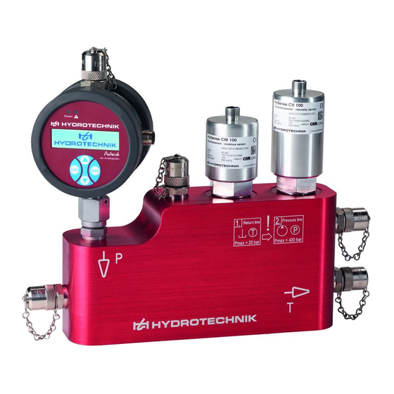
START-UP OF THE SERVICE MEASURING KIT 4. START-UP OF THE SERVICE MEASURING KIT Figure 3 depicts the connected CX 197. The next section describes the start-up in more detail. Figure 3: Connections to the CX 197 A: Supply line (pressure connection) D: Connection for ventilation B: Connection to sensors E: Drain (tank connection) -
Page 14: Installation In The Pressure Line
START-UP OF THE SERVICE MEASURING KIT • For the pressure connection, use the hose line with the check valve on one side. First connect the simple side (without check valve) to the CX 197 on the input side (point A, Figure 3) •... -
Page 15: Installation In The Return Line
START-UP OF THE SERVICE MEASURING KIT Alternative: Figure 5: Installation situation of the CX 197; left: recommended installation; right: alternative installation 4.1.2 Installation in the return line If it is possible to establish pressure in the return line that generates a necessary flow (e.g. -
Page 16: Setting The Flow
START-UP OF THE SERVICE MEASURING KIT Caution Danger of contamination with other oil Since the CX 197 could still be filled with incompatible oil from the last measurement, empty or flush the CX 197 with at least 200 ml of oil. 4.1.3 Setting the flow Since the Patrick particle monitor requires a constant flow between 50 and 400 ml/min, attention should be paid to the appropriate flow. -
Page 17: Connecting The Sensors
START-UP OF THE SERVICE MEASURING KIT Warning Risk of burns When ventilating, note that skin contact with hot oil can cause burns. Adjust the oil pressure so that only a little oil escapes. 4.3 Connecting the sensors Figure 7 shows the CAN data line together with the power pack and the data line. - Page 18 START-UP OF THE SERVICE MEASURING KIT Note Power supply The measurement instrument's rechargeable battery is only sufficient for a limited time. For longer supply of the sensors, either connect the power pack of the measurement instrument or operate the sensors with the included power pack. For this, connect the power pack to the three-way CAN cable.
-
Page 19: Use With A Multisystem Measurement Instrument
MultiSystem 5060Plus, MultiSystem 5070 or MultiSystem 4070. If your measurement instrument has earlier firmware, it's easy to update the instrument via the HYDROTECHNIK software “hydrocenter” (can be downloaded from the homepage HYDROTECHNIK.com). Connect the data cable to the 8-pin CAN connection on the measurement instrument as described in Chapter 4.3. -
Page 20: Use With The Multisystem 5070/4070
Furthermore, you can also select the unit system that should be used to display the units. These include the metric system and the US measurement system. 5.1.1 Opening the “HySense CX 197” function Use the menu key to reach the main menu (home). By selecting the folder “Extras / Special applications / Oil condition”... -
Page 21: Operating The "Hysense Cx 197" Function
USE WITH A MULTISYSTEM MEASUREMENT INSTRUMENT Figure 10: Main menu of the user function “HySense CX 197” for the MultiSystem 5070/4070 5.1.2 Operating the “HySense CX 197” function If you start the “HySense CX 197” function, there is an automatic search for connected oil condition sensors. -
Page 22: Selection Of The Metering Point
USE WITH A MULTISYSTEM MEASUREMENT INSTRUMENT ONLINE/OFFLINE mode ONLINE mode means that the sensors (at least partially) were detected and the evaluation of currently measured measurement values is correct. You are in a position to save measurements or perform an interval measurement. The measurement values and evaluation are updated every three seconds. - Page 23 USE WITH A MULTISYSTEM MEASUREMENT INSTRUMENT If you create or edit a metering point, the menu depicted on the left in Figure 12 appears. Here, you can use the ENT key to reach the field to be edited. In the two upper entries, the name and the oil are defined.
- Page 24 USE WITH A MULTISYSTEM MEASUREMENT INSTRUMENT Figure 14: Creating an oil in the oil database An oil is defined with the following characteristic values: • Viscosity at 40°C (ν • Viscosity at 100°C (ν • Density at 15°C • Pour point •...
-
Page 25: Evaluation Of The Measurements - Condition Menu
USE WITH A MULTISYSTEM MEASUREMENT INSTRUMENT Table 4: Order of magnitude of the permittivity for oil types: Permittivity ε Oil type Descriptions HL, HLP, HLPD, HVLP, Mineral oil 2.0– 2.4 HVLPD Polyalphaolephine HEPR 2.3– 2.9 (PAO) Synthetic ester/ Native HEES / HETG 2.9–... - Page 26 USE WITH A MULTISYSTEM MEASUREMENT INSTRUMENT displayed at the left bottom. With the F4 and F5 keys, you can select the measurement series. Figure 15 depicts the ONLINE mode on the right. Here, the measurement values are read from the sensors automatically and evaluated in color. With the F3 color: OFFL.
- Page 27 USE WITH A MULTISYSTEM MEASUREMENT INSTRUMENT Figure 16: Oil condition on the “Oil condition menu” Oil humidity: If you select the “Oil humidity” element from the condition menu, a window opens (Figure 17), on which the measurement value of the relative humidity is depicted, Here too, you can adjust the warning limit with the F2: EDIT key.
- Page 28 USE WITH A MULTISYSTEM MEASUREMENT INSTRUMENT Particle contamination: In the particle analysis, on the one hand the particle classes are displayed with the limits to be edited; and on the other, the current flow. The flow has to be provided with warning limits to warn if the flow is at its limits. Figure 18: Particle contamination on the “Oil condition”...
-
Page 29: Display Of The Measurement Values
USE WITH A MULTISYSTEM MEASUREMENT INSTRUMENT 5.1.5 Display of the measurement values If you are on the condition menu (Figure 15), you can use the F2 key (“DISPLAY”) to reach the measurement value table that is depicted in Figure It consists of 4 pages, which can be reached the pressing the right/left arrow keys. -
Page 30: Exporting The Measurement Data
USE WITH A MULTISYSTEM MEASUREMENT INSTRUMENT 5.1.6 Exporting the measurement data The MultiSystem 5070/4070 automatically creates CSV files with all measurement data (measurement values, limits, warning limits, calculations, and conditions). To export this file to a computer, there are two possibilities: 1. -
Page 31: Evaluating Measurements
The CSV measurement files can be copied into a template file that is available for download on the HYDROTECHNIK GmbH homepage at: HYDROTECHNIK.com. The tool is called: “Analysis tool_HySense® CX 197.” The file can be opened with Excel and the entire measurement file transferred to the tool with copy and paste. -
Page 32: Use With The Multisystem 5060Plus
USE WITH A MULTISYSTEM MEASUREMENT INSTRUMENT 5.2 Use with the MultiSystem 5060Plus 5.2.1 Opening the “Measuring section CX 197” function With the menu key, you can use the menu guidance to reach the main menu, where you will find the “Measuring section CX 197” function under “Special applications.”... - Page 33 USE WITH A MULTISYSTEM MEASUREMENT INSTRUMENT In the blue field on the lower part of the display, you can see the selected metering point with a note about whether the sensors are connected to the measurement instrument and detected (online mode) or whether the measurement is in offline mode.
-
Page 34: Measurement Menu "Measuring Section Cx 197
USE WITH A MULTISYSTEM MEASUREMENT INSTRUMENT 5.2.3 Measurement menu “Measuring section CX 197” With the F2 key “Measure” on the main menu (Figure 24), you can reach the measurement menu that is depicted in Figure 25. Figure 25: Measuring menu of the "Measuring section CX 197” function Only the metering point can be selected with the cursor on this menu. - Page 35 USE WITH A MULTISYSTEM MEASUREMENT INSTRUMENT Figure 26: left: Metering point selection: right: EDIT menu of the metering point Figure 27: Oil database If you select the oil type with the Enter key from the metering point selection on the Edit menu (Figure 26 right), you reach the oil database that is depicted in Figure 27.
- Page 36 USE WITH A MULTISYSTEM MEASUREMENT INSTRUMENT • Viscosity at 40°C (ν • Viscosity at 100°C (ν • Density at 15°C • Pour point • Permittivity at 40°C (ε Figure 28: Creating an oil with oil parameters: right: Help window for selection of the permittivity at 40°C Note Parameters for “own oil”...
-
Page 37: Display Of The Measurement Values
USE WITH A MULTISYSTEM MEASUREMENT INSTRUMENT Table 6: Order of magnitude of the permittivity for oil types: Permittivity ε Oil type Descriptions HL, HLP, HLPD, HVLP, Mineral oil 2.0– 2.4 HVLPD Polyalphaolephine HEPR 2.3– 2.9 (PAO) Synthetic esters. HEES / HETG 2.9–... -
Page 38: Exporting The Measurement Data
USE WITH A MULTISYSTEM MEASUREMENT INSTRUMENT Figure 29: Measurement value table In the first three windows, the direct measurement values for a particular time stamp are saved. The fourth window displays the oil with its oil parameters that was selected for the measurement. Windows 5-8 reflect the limits set at the time of the measurement. -
Page 39: Evaluation Of The Measurements - Condition Menu
USE WITH A MULTISYSTEM MEASUREMENT INSTRUMENT 5.2.7 Evaluation of the measurements - Condition menu If you are on the Condition menu (Figure 24), you can use the F5 key (“DETAIL”) to reach the oil condition menu that is depicted in Figure 30Fehler! Verweisquelle konnte nicht gefunden werden.. - Page 40 USE WITH A MULTISYSTEM MEASUREMENT INSTRUMENT Figure 31: Oil condition on the “Oil condition” menu Oil humidity: If you select the “Oil humidity” element from the Condition menu, a window opens (Figure 32), on which it is signaled with three indicators whether the relative oil humidity is greater than 50%, 75% or greater than 95%.
- Page 41 USE WITH A MULTISYSTEM MEASUREMENT INSTRUMENT • Flow verification: If the flow is set too high or low, this indicator turns red. Figure 33: Particle contamination on the “Oil condition” menu Oil temperature: If you select oil temperature, then it is indicated with a traffic light control whether the set limit values for the oil temperature have been underrun or exceeded.
-
Page 42: Interpretation Of The Measurement Results
Interpretation of the measurement results 6. Interpretation of the measurement results Thanks to the particle monitor, you can get information about the degree of contamination of the oil with foreign particles. The humidity sensor specifies the dissolved humidity content directly. These variables provide direct insights into the wear of the oil due to particles and/or humidity. -
Page 43: Permittivity (Dielectric Constant)
Interpretation of the measurement results • Polymer chains can be deposited in the system (e.g. In the tank or filter) In order to determine oxidation for certain, a laboratory analysis with determination of the oxidation count (or the TBN Total Base Number) is necessary. -
Page 44: Conductivity
Interpretation of the measurement results Slow increase This indicates (as for viscosity) an oil aging that can have various causes: • Oxidation (see point 6.1.1 viscosity) • Reduction of additives: Due to the usually polar reduction or decomposition products, the permittivity increases •... -
Page 45: Service And Accessories
If it is in frequent use, we recommend recalibrating it every 12 months. Have the service measuring kit ® calibrated by the manufacturer with the Patrick sensors, HySense CV 100, and ® HySense CM 100. HYDROTECHNIK maintains a high-performance calibration laboratory. ® HySense CX 197... -
Page 46: Accessories And Spare Parts
In this case, the service measuring set must be calibrated to the oil used. Please contact our service at: Tel.: +49 6431 4004-555 E-mail: service@hydrotechnik.com 7.3 Accessories and spare parts Part Part number Remarks HySense ®... - Page 47 Service and accessories For use of the individual sensors: Part number Description Remarks 8824-T7-00.00 Interface cable M12 x 1; For configuration and reading out of the internal memory plug; 8-pin/D-SUB connection; 9-pin Required with the “8824-T7-00.00” 8808-50-01.03 Y-distributor M12 8-pin; connector, plug, connector interface cable 8812-00-00.36...
- Page 48 Service and accessories Hydrotechnik GmbH D-65549 Limburg Tel.: +49 6432 4004-0 Email: info@hydrotechnik.com www.hydrotechnik.com L3402-CX10-D100-EN ® HySense CX 197...
Need help?
Do you have a question about the HySense CX 197 and is the answer not in the manual?
Questions and answers