Table of Contents
Advertisement
Quick Links
Advertisement
Table of Contents

Related Manuals for Hydrotechnik MultiSystem 5060


Summary of Contents for Hydrotechnik MultiSystem 5060
- Page 1 MultiSystem 5060 Operating Instructions Manual MultiSystem 5060 Universal Portable Measuring System Operating Instructions Manual Revision 1.8 / March 07, 2012 Firmware Version 5.4a TKZ L3160-00-70.00EN © Hydrotechnik GmbH • All rights reserved Page 1 of 55 Rev. 1.8/120307EN...
-
Page 2: Table Of Contents
Use as agreed..................6 Warranty regulations ................6 Obligations to the customer ............... 6 Authorized staff .................. 6 Description of the measuring instrument ........7 Qualities of the MultiSystem 5060............7 Connectors..................7 3.2.1 Characteristics of highspeed analog inputs ............7 3.2.2 Characteristics of analog inputs................ - Page 3 Start the MultiXtend ..................52 Connection of external measuring devices ........52 Cleaning and maintenance............53 Cleaning................... 53 Maintenance ..................53 SD card replacement ............... 53 Repair ....................55 © Hydrotechnik GmbH • All rights reserved Page 3 of 55 Rev. 1.8/120307EN...
-
Page 4: Safety
Additionally, the basic USB specifica- tions are not fuliflled and maintained completely by all manufacturers. This is why Hydrotechnik guarantees the full support of the printer "PIXMA iP 4200" of Canon Inc., only. Please ask our cus- tomer service, whether your printer is supported. -
Page 5: Introduction
Range of validity The manual on hand is valid for measuring instruments named "MultiSystem 5060". It adresses to the operator of this instrument, that means the person, who works with the instrument. The manual is not a technical manual. Please contact our service staff for questions, that exceed the contents of this manual. -
Page 6: Use As Agreed
The warranty benefit is by our choice through repair of defective parts or replacement by intact parts. Send your instrument with an invoice copy or delivery note copy to Hydrotechnik. The adress is men- tioned at the end of this manual. -
Page 7: Description Of The Measuring Instrument
(linearisation). A confusion of the sensor and the entry of specific sensor data are things of the past. You can connect sensors without ISDS designation to the MultiSystem 5060. The entry of the sensor parameters is then done in clear operation menus. -
Page 8: Characteristics Of Analog Inputs
4.75 kΩ gnal Ground 100 mA Direction signal 1 nF 33 V DC VDR Transil diode 4.75 kΩ Shield ISDS Ub*: power supply during mains operation 24 V © Hydrotechnik GmbH • All rights reserved Page 8 of 55 Rev. 1.8/120307EN... -
Page 9: Characteristics Of Digital Trigger Input
Attention Possible damage to external devices! A voltage of +5 Volt is present at pin 3. This is used to supply the Bootload-Adaptor of Hydrotechnik. Please consider this when doing individual wirings. © Hydrotechnik GmbH • All rights reserved Page 9 of 55... -
Page 10: Characteristics Usb Interfaces
In normal operation, either the battery or power pack icon is displayed. If the battery icon flashes during mains operation, the batteries are ei- ther missing, defective or deep-cycled. Possibly the battery cable isn't plugged correctly. © Hydrotechnik GmbH • All rights reserved Page 10 of 55 Rev. 1.8/120307EN... -
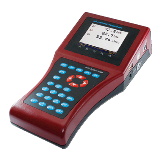
Page 11: Keyboard
8MB per series of measurements (2 million values) analog ± 0.15% of final value Error limits digital ± 0.02 % of measured value (resolution 20 ns) © Hydrotechnik GmbH • All rights reserved Page 11 of 55 Rev. 1.8/120307EN... -
Page 12: Startup
Hydrotechnik power pack. The instrument is equipped with an internal battery. This is pre-charged by Hydrotechnik and must be charged for at least 14 to 16 hours, before the instrument can be used. -
Page 13: Operation
If you use ISDS sensors, the sensor parameters will be set automati- cally. If you use other sensors, you have to program the sensor pa- rameters before you can carry out measurements. © Hydrotechnik GmbH • All rights reserved Page 13 of 55 Rev. 1.8/120307EN... -
Page 14: Select Operation Language
Save changes: Connect sensors 1. Switch the instrument off. 2. Connect the desired sensors to the inputs (see section 3.2 on page 7). 3. Switch the instrument on. © Hydrotechnik GmbH • All rights reserved Page 14 of 55 Rev. 1.8/120307EN... -
Page 15: Enter Sensor Parameters
Select between „0/20 mA“ – „4/20 mA“ – „0/10 V“ – „± 10 V“ – „0,5/4,5 V“ – „1/5 V“ – „2/10 V". Measuring range Enter the beginning and end of the measuring range and confirm with © Hydrotechnik GmbH • All rights reserved Page 15 of 55 Rev. 1.8/120307EN... -
Page 16: Collect Measuring Data
Storing time and scan rate define, how often and how long measure- ment data shall be stored. Be aware that if you store too many meas- urement data, the later evaluation and presentation will become more difficult. © Hydrotechnik GmbH • All rights reserved Page 16 of 55 Rev. 1.8/120307EN... -
Page 17: Connect Pc And Transfer Measurement Data
In the shown example, the series of measurement 004 and 005 has been selected for deletion already, a (*) is displayed beside of them. Pressing displays information on the highlighted series of meas- urement. © Hydrotechnik GmbH • All rights reserved Page 17 of 55 Rev. 1.8/120307EN... -
Page 18: Print Measurement Data
(> 2 sec.) Wait until the beginning of the initialisation is displayed; then press: Confirm resetting: A green message window will be displayed where the data storage is confirmed. © Hydrotechnik GmbH • All rights reserved Page 18 of 55 Rev. 1.8/120307EN... -
Page 19: Operation Software
Special Applications functions for the operation of optional features (e.g. CAN, automatic test sequences, particle counter, load valve, …) Press to select the desired submenu and then press © Hydrotechnik GmbH • All rights reserved Page 19 of 55 Rev. 1.8/120307EN... -
Page 20: Available Functions
See the explanations in section 6.10 on page 41. Use an USB stick See the explanations in section 6.11 on page 42. Submenu “Channels” The MultiSystem 5060 offers 24 channels: Ch1 ... Ch8 measuring channels; sensor connectors at the rearside of the device... -
Page 21: Configure Trigger Input (Ch9)
6.3.2 Configure trigger input (Ch9) You can only assign a name to the trigger input. Please obtain the technical data (see page 11) for allowed input signals. © Hydrotechnik GmbH • All rights reserved Page 21 of 55 Rev. 1.8/120307EN... -
Page 22: Configure Trigger Output (Ch10)
FORMULA, see below) Additional functions loads stored channel parameters from the database stores the current channel parameters in the database saves the channel settings and leaves the submenu © Hydrotechnik GmbH • All rights reserved Page 22 of 55 Rev. 1.8/120307EN... - Page 23 Channel 11: calculation K7 – K8 = dV1 in liter • Channel 12: calculation dK11/dt Q1 in liter per second • Channel 13: calculation K12 * 60 = Q2 in liter per minute © Hydrotechnik GmbH • All rights reserved Page 23 of 55 Rev. 1.8/120307EN...
-
Page 24: Submenu "Display
Press to use the set measuring range of each channel as scaling ranges. © Hydrotechnik GmbH • All rights reserved Page 24 of 55 Rev. 1.8/120307EN... -
Page 25: Submenu „Memory
(hardware filter). Otherwise this option is blocked. At scan rates < 100 ms, the hardware filters should not be dynamic. This is possible but increases the risk of malfunctions. © Hydrotechnik GmbH • All rights reserved Page 25 of 55 Rev. 1.8/120307EN... - Page 26 START/STOP: trigger 1 starts the storing, trigger 2 stops it 7. Define trigger type and trigger value of trigger 2 like described in the items 3. and 4. © Hydrotechnik GmbH • All rights reserved Page 26 of 55 Rev. 1.8/120307EN...
-
Page 27: Submenu "Device
3. Confirm changes and leave function: 6.6.2 Enter date 1. Open function: 2. Enter day: 3. Enter month: 4. Enter year: 5. Confirm changes and leave function: © Hydrotechnik GmbH • All rights reserved Page 27 of 55 Rev. 1.8/120307EN... -
Page 28: Enter Time
50 Hz hardware filter is switched for Ch1 ... 6; peak pressures are supressed; ideal for static measurements or slow processes Individual each channel can be defined individually (dynamic / standard / damped) © Hydrotechnik GmbH • All rights reserved Page 28 of 55 Rev. 1.8/120307EN... -
Page 29: Set Software Filter
The printer will be detected automatically and must not be selected. The format can be chosen between DIN A4 and US Letter: 1. Open function: 2. Select format: 3. Confirm changes and leave function: © Hydrotechnik GmbH • All rights reserved Page 29 of 55 Rev. 1.8/120307EN... -
Page 30: Select Keyboard
5. Confirm changes and leave function: These options can be set: Module select whether an Ethernetmodule is connected (YES) or not enter the IP-address that the MultiSystem 5060 shall have in the Ethernet network Port enter the communication port of your Ethernet network Password... -
Page 31: Setup Menu
“Spe- Function “CAN Tx Msg” cial Applications”. This function is now contained in the menu “Special Applications”. See section 6.8.4 “Load valve” on page 36. © Hydrotechnik GmbH • All rights reserved Page 31 of 55 Rev. 1.8/120307EN... -
Page 32: Display Software Information
6. Press to confirm the entries and leave the submenu. 6.6.15 Display software information When calling the Hydrotechnik customer service department, you should have the required information available. These are contained on the information screen: 1. Display information: 2. Display desired information: 3. -
Page 33: Submenu "Special Applications
CAN device PATRICK display and save the data of the particle counter Load valve display and save the data from the Hydrotechnik load ® valve HySense PR 326 to highlight the desired submenu and then press 6.8.1... - Page 34 (± 0.2 bar). The test result is stored in a database that can be evaluated in the instrument and transferred to a Arithmetic test (English) – Graphical presentation of measured and calculated variables with HYDRO- gen/HYDROrun. © Hydrotechnik GmbH • All rights reserved Page 34 of 55 Rev. 1.8/120307EN...
-
Page 35: Canopen Device
After modifying the values you have to press to transmit the val- ues to the particle counter. Press to terminate the configuration. © Hydrotechnik GmbH • All rights reserved Page 35 of 55 Rev. 1.8/120307EN... -
Page 36: Load Valve Hysense Ql 326
Operation mode “Sine” The load valve follows a sine curve that can be defined with three pa- rameters. The values entered in the screenshot result in the shown curve: © Hydrotechnik GmbH • All rights reserved Page 36 of 55 Rev. 1.8/120307EN... -
Page 37: Submenu "Show" (Function Bar)
1. Open submenu “Show”: 2. Select series of measurements: 3. Select output format: 4. Set further options (see below). 5. Present series of measurements: © Hydrotechnik GmbH • All rights reserved Page 37 of 55 Rev. 1.8/120307EN... -
Page 38: Select Series Of Measurements
Assign symbols and colors 1. Highlight channel: 2. Enable/disable channel presentation: 3. Select symbol: 4. Select color: 5. End channel configuration: © Hydrotechnik GmbH • All rights reserved Page 38 of 55 Rev. 1.8/120307EN... -
Page 39: Define Scaling
Now you may repeat these steps to show more detailed values, or press to undo the “zooming” step-by-step. © Hydrotechnik GmbH • All rights reserved Page 39 of 55 Rev. 1.8/120307EN... -
Page 40: Presentation Type Graph
Like in the spot func- tion, you can now choose move factors with the keys toggle between the different calculation methods pressing © Hydrotechnik GmbH • All rights reserved Page 40 of 55 Rev. 1.8/120307EN... -
Page 41: Show Menu Setup
In the image the measurement series 002 and 003 are selected for deletion. The measurement series 001 is highlighted. Press to dis- play information on it. The deletion cannot be undone. © Hydrotechnik GmbH • All rights reserved Page 41 of 55 Rev. 1.8/120307EN... -
Page 42: Submenu „Ustick
1. Highlight „default name“: 2. Start definition: 3. Enter desired header; you may use all alphanumeric characters. 4. Confirm header: © Hydrotechnik GmbH • All rights reserved Page 42 of 55 Rev. 1.8/120307EN... - Page 43 Here you can see the size of the total and of the available memory, and a list of files contained on the stick that are interesting for the MultiSystem 5060. Press to leave the submenu. © Hydrotechnik GmbH • All rights reserved Page 43 of 55 Rev. 1.8/120307EN...
-
Page 44: Special Functions
After entering all CAN parameters you can assign a name and store them: – enter a name, use to toggle between the entry of capital and small letters – – store parameters and entered name. © Hydrotechnik GmbH • All rights reserved Page 44 of 55 Rev. 1.8/120307EN... -
Page 45: Graphic Presentation In Display Menu
You can use the following functions: switches to the graphical presentation of MinMax values displays scaling information instead of measured values stops the actualisation of the measured values ("freezes" the display) © Hydrotechnik GmbH • All rights reserved Page 45 of 55 Rev. 1.8/120307EN... -
Page 46: Coupling Of Several Measuring Instruments
MultiSystem 5060 Operating Instructions Manual Coupling of several measuring instruments You can couple several MultiSystem 5060 measuring instruments and increase the number of available input channels with nearly no limita- tions. But please be aware of that: • series of measurements with more than 24 input channels cannot be processed by the evaluation software HYDROcomsys •... -
Page 47: Program Instruments
4. Program the trigger output „AKTIV“ and set it to „SP_TRIG“ (for- warding of the trigger signal to the next Slave). This is required for serial coupling, only. © Hydrotechnik GmbH • All rights reserved Page 47 of 55 Rev. 1.8/120307EN... -
Page 48: Start Recording
7.4.4 Transfer and evaluate measured values Transfer the measured values from all instruments to a PC. Use the function „Combine“ of the Hydrotechnik software HYDROcom, to combine the series of measurement. How to use the USB stick Hint USB sticks are supported by firmware version 4.3 and later. -
Page 49: Firmware Update Using The Usb Stick
1. Copy the new firmware version on the USB stick. The file must be located on the top file system level, not in a directory. 2. Switch on the MultiSystem 5060 and wait until the measured val- ues are displayed. -
Page 50: Connect Multixtend A And T
Connect MultiXtend A and T You can use the MultiXtend A and T to connect additional analog sen- sors or thermocouples to the MultiSystem 5060. Their signals are digi- talised by the MultiXtend and transmitted to the CAN input of the measuring instrument. -
Page 51: Activate Multixtend Power Supply
3. Highlight the function „Power CAN“. 4. Press to set the function to „ON“. 5. Press to confirm the changes and leave the setup menu. © Hydrotechnik GmbH • All rights reserved Page 51 of 55 Rev. 1.8/120307EN... -
Page 52: Start The Multixtend
Connection of external measuring devices You may connect external measuring devices (e.g. Multimeters) to the RS232 interface of the MultiSystem 5060 and assign the measuring signals to a special channel. The measuring devices must support the output data format “Voltcraft” or “Metex”. -
Page 53: Cleaning And Maintenance
This device is maintenance-free. However, it is still essential to regu- larly re-calibrate it. If the device is in continuous use, we recommend re-calibration every 2 years. Hydrotechnik has an efficient calibration laboratory, please contact: Hydrotechnik GmbH Holzheimer Straße 94-96 • D-65549 Limburg Tel.: +49 (0) 6431 –... - Page 54 Be careful not to damage or clamp the connection wires. Hint A new SD card must be formatted before you can use it. Please see section 6.6.14 on page 31. © Hydrotechnik GmbH • All rights reserved Page 54 of 55 Rev. 1.8/120307EN...
-
Page 55: Repair
Customer Service Address Please contact the Hydrotechnik Customer Service Department: Hydrotechnik GmbH Holzheimer Straße 94-96 • D-65549 Limburg Tel.: +49 (0) 6431 – 4004 0 • Fax: +49 (0) 6431 – 45308 E-Mail: info@hydrotechnik.com •...
Need help?
Do you have a question about the MultiSystem 5060 and is the answer not in the manual?
Questions and answers