
Related Manuals for Hydrotechnik MultiSystem 5070


Summary of Contents for Hydrotechnik MultiSystem 5070
- Page 1 MultiSystem 5070 Universal Portable Measuring System Operating Instructions Firmware Version 1.1 Handbook Version 1.0...
-
Page 2: Table Of Contents
Operation General safety and warning information ..... 4 Switch the instrument On and Off..... 23 Handling information for the MultiSystem 5070. 4 Operation of the instrument software....24 Information about the use of sensors Navigate in the instrument software .... 25 and cables............ - Page 3 Transfer and evaluate measured values..124 Connecting MultiXtend A and T ...... 124 Activate CAN bus........125 Program CAN channels ......126 Activate MultiXtend power supply ....126 Starting the MultiXtend....... 127 Viscosity-compensated volume flow rate measuring ..........128 Firmware Version 1.1 MultiSystem 5070...
-
Page 4: General Safety And Warning Information
Unplug the power cable if you detect smoke or there is an odor, or if the power cable is damaged. • Ensure sufficient grounding of your system. Inadequate grounding may cause incorrect measurements. Handling information for the MultiSystem 5070 • Never expose the instrument to excessive heat or moisture and observe the technical data. •... -
Page 5: Information About The Use Of Sensors And Cables
Never disassemble, repair or modify the batteries. • Never short-circuit the contacts of batteries. • Use only batteries that are installed or delivered by HYDROTECHNIK. • Only charge the battery while it is mounted in the instrument. • Dispose of used batteries as hazardous waste. Cover the contacts with insulation tape. -
Page 6: Introduction
Scope The manual on hand is valid for measuring instruments named MultiSystem 5070. It is intended for the operator of the instrument, that means the person who works with the instrument. This is not a technical man- ual. Please contact our customer service for questions, that go beyond the contents of this manual. -
Page 7: Limitation Of Liability
HYDROTECHNIK. The products of HYDROTECHNIK GmbH are designed for a long life. They represent the state of the art and their functions have been individually checked before delivery. -
Page 8: Intended Use
Please send the instruments for which you have made a warranty claim post- age-paid and with a copy of the invoice or the delivery slip to HYDROTECHNIK customer service. You can find the address at the end of this manual. -
Page 9: Customer Obligations
Personnel for installation and maintenance Persons are considered to be authorized if they have been trained in all as- pects of the instrument and have read and understood this manual completely. Firmware Version 1.1 MultiSystem 5070... -
Page 10: Description Of The Measuring Instrument
The MultiSystem 5070 is a practice-oriented, user-friendly hand-held meas- uring instrument assisting the user with daily measuring functions. When using sensors with ISDS (intelligent sensor detection), the MultiSystem 5070 auto- matically identifies the connected sensors during switch-on and adopts all parameters: Measurement range, physical measurement variables, unit of measurement, signal output and characteristic curve (linearisation). -
Page 11: Connections
Input Ch7 – frequency/analog input Input Ch8 – frequency/analog input Input Ch5 – analog input Power supply – power pack Input Ch3 – analog input Digital input and output Input Ch6 – analog input Input CAN2 Firmware Version 1.1 MultiSystem 5070... -
Page 12: Characteristics Of Analog Inputs
Protection type Signal I [mA] 113 Ω 35 nF 5VDC Transile diode Ground 100mA Current limiting Signal U [V] 8.8 kΩ 35 nF ± 15VDC Transile diode Shield ISDS Power supply during mains operation 24 V Firmware Version 1.1 MultiSystem 5070... -
Page 13: Characteristics Of Frequency/Analog Inputs
Function Limitation Protection type Signal (f) 100 k 33 nF 15VDC VDR Transile diode Ground 100mA Signal direction 100 k 33 nF 15VDC VDR Transile diode Shield ISDS Power supply during mains operation 24 V Firmware Version 1.1 MultiSystem 5070... -
Page 14: Characteristics Of Digital Signal Input
Function Limitation Protection type Signal 30VDC VDR Transile diode Ground 1 mA constant current Characteristics digital signal output Jacks of the digital input/output. Pin assignment Function Limitation Protection type Ground Signal Ub/10mA VDR Transile diode Firmware Version 1.1 MultiSystem 5070... -
Page 15: Characteristics Combi-Jack Can / Rs 232
Power supply for the measuring instrument CAN_H CAN_L The measuring instrument switches the power supply on automatically via the CAN 2 jack. The meas- uring instrument is then only to be used for data recording. Firmware Version 1.1 MultiSystem 5070... -
Page 16: Characteristics Usb Interfaces
~ 5 VDC / 500 mA Ground black – USB Type B: Device interface Function Designation Remarks Signal D+ green twisted cable Signal D– white twisted cable Not used Ground black – Firmware Version 1.1 MultiSystem 5070... -
Page 17: Display
In normal operation, either the battery or power pack icon is displayed. If the battery icon flashes during mains operation, the batteries are either missing, defective or deep-cycled. Possibly the battery cable isn't plugged correctly. Firmware Version 1.1 MultiSystem 5070... -
Page 18: Keyboard
Input 8 or TUVÜ Input 9 or WXYZ Input 0 or space Dash, period, special charac- Delete single character ters Use the key to enter special digits, e.g. ( ) * / @ ° … Firmware Version 1.1 MultiSystem 5070... -
Page 19: Hydrocom Software Package
SD card 4 GB, max. 500 series of measurements, max. 8MB per series of measurements (6 million values) Tolerances Analog ± 0.10 % of final value, digital ± 0.02 % of measured value (resolution 20 ns) Firmware Version 1.1 MultiSystem 5070... -
Page 20: Commissioning
To maintain all claims against the shipping company you should document all possible transportation damage (e.g. by taking photos and signing a written protocol), before you unpack the measuring instrument. HYDROTECHNIK is not responsible for transportation damage and will as- sume no liability. Scope of delivery Carefully remove the transportation packing. -
Page 21: Charge Batteries
The lithium ion battery integrated in the measuring instrument will be charged as soon as the instrument is supplied by a HYDROTECHNIK power pack. The instrument is equipped with an internal lithium ion battery. This has only been slightly charged at the factory. Charge them for 2 hours before you put the instrument into operation. -
Page 22: Operation
The software HYDROcom which is part of delivery will not be explained in this manual. Please refer to the online help and the separate software documentation. Firmware Version 1.1 MultiSystem 5070... -
Page 23: Switch The Instrument On And Off
(> 2 sec.) The instrument saves all data and settings before the instrument software is shut down. If you hold the down for longer than 5 seconds, this switches the instrument off without saving. Firmware Version 1.1 MultiSystem 5070... -
Page 24: Operation Of The Instrument Software
If the measurement display is shown, press the key to display the Home menu. Menus have up to 3 x 3 icons. Each icon takes you to the next menu level or to a dialog. Firmware Version 1.1 MultiSystem 5070... -
Page 25: Navigate In The Instrument Software
Number keys You can use the number keys to select a menu quickly. The number keys correspond to the icon position in the menus. If you press a number key, the corresponding menu or dialog opens. Firmware Version 1.1 MultiSystem 5070... -
Page 26: Favorites
Assigning a favorite 1 Select favorite on the menu 2 Open favorite selection: (press at the same time) 3 Select and confirm menu or dialog: Firmware Version 1.1 MultiSystem 5070... -
Page 27: User-Defined Softkeys
Softkeys: Symbols/text On the User profiles dialog, select whether softkeys are displayed as symbols or text. See Softkeys on page 92. See Softkeys: Symbols/text on page 137. Firmware Version 1.1 MultiSystem 5070... -
Page 28: Select Operating Language
2 Open Setting menu: 3 Open Unit menu: 4 Open General settings menu: 5 Select Language with and open with dialog field. 6 Select language on the dialog field: 7 Confirm changes and exit dialog: Firmware Version 1.1 MultiSystem 5070... -
Page 29: Setting Date And Time
9 Confirm changes and exit dialog: Connect sensors 1 Switch the instrument off. 2 Connect the desired sensors to the inputs. See Chapter Connections on page 11. 3 Switch the device on. Firmware Version 1.1 MultiSystem 5070... -
Page 30: Enter Sensor Parameters
All channels dialog: 5 Highlight channel: 6 Start programming: 7 Highlight and select the dialog entry: 8 Highlight value: or enter value: z. B. 12,5 9 Confirm value: 10 Confirm changes and exit dialog: Firmware Version 1.1 MultiSystem 5070... - Page 31 Please observe the additional information in chapter Chapter Linearisa- tion table on page 113. LOAD Press to load sensor parameters from the sensor data base. SAVE Press to save the current sensor parameters in the sensor database. Firmware Version 1.1 MultiSystem 5070...
-
Page 32: Record Measuring Data
A trigger is a condition that has to happen to make the storing of measurement data start or stop. In this case, no trigger is defined. Please see section Chapter Trigger function on page 101 for further infor- mation on how to use the trigger function. Firmware Version 1.1 MultiSystem 5070... -
Page 33: Connect A Pc And Transfer Data
The internal memory has two partitions: • DATA-VOL This is the general memory for files (measurement series, images, etc.) • DOCU-VOL This is where you will find the operating instructions, data sheets and soft- ware for this instrument. Firmware Version 1.1 MultiSystem 5070... -
Page 34: Delete Measuring Data
4 Select measurement series (optional): 5 Delete: 6 Delete selected measurement series or all measurement series: 7 Confirm deletion with or cancel with The deletion cannot be undone. Search function, see Search series on page 62 Firmware Version 1.1 MultiSystem 5070... -
Page 35: Reset Device
3 Wait until the beginning of the initialization is displayed and then press: The selection list of the available operation languages will be displayed; here you may select the ones desired. Then the device will be reset and restarted. Firmware Version 1.1 MultiSystem 5070... -
Page 36: Operating Software
Operating software Operating software The operating software of the MultiSystem 5070 will be presented and ex- plained on the following pages. Home MENU opens the Menu; you can operate all functions of the MultiSystem 5070 from here. For the following explanations, it is assumed that the Menu is displayed. -
Page 37: Available Menus
Setting Settings for the channels, display, device and saving Extras Settings for the USB stick, special applications and games Favorites Here you can save menus or dialogs as favorites. See Favorites on page 133. Firmware Version 1.1 MultiSystem 5070... -
Page 38: Start Recording
(channel selection, storage duration, triggers, etc.) can be set on the Device menu. Measurement series Name of the measurement series; press to overwrite the proposal name Filename Here you may enter a (different) name for the measurement series data file Firmware Version 1.1 MultiSystem 5070... - Page 39 Start the saving with Note You can enter any free text here Open saved measurements See Series of measurements on page 46. Use USB stick See Flash drive File manager on page 107. Firmware Version 1.1 MultiSystem 5070...
-
Page 40: Measured Values Display
Tiles/page on page 77 Graphic view y=f Graphic presentation in display menu on page 119 Graphic view y=f Graphic presentation in display menu on page 119 MinMax view Measured values with MinMax on page 42 Firmware Version 1.1 MultiSystem 5070... -
Page 41: Measured Values With Their Units
Operating software Measured values with their units Display change Display change on page 40 The units are displayed to the right of each measured value. Firmware Version 1.1 MultiSystem 5070... -
Page 42: Measured Values With Minmax
Display change on page 40 To the right of each measured value display, the measured minimum value (upper left) and maximum value (bottom right) are displayed. Symbols in the measured value display Channel with ISDS sensor. Channel is recorded Firmware Version 1.1 MultiSystem 5070... -
Page 43: Configurations
Saving a new configuration 1 Select the Save configuration dialog: 2 Enter File name to toggle between capital and small letters. 3 Enter Description to toggle between capital and small letters. 4 Save configuration and exit dialog: Firmware Version 1.1 MultiSystem 5070... -
Page 44: Loading A Saved Configuration
1 Select the Delete configurations dialog: 2 Select File name: 3 On the dialog window, select from the list of configurations: 4 Delete: 5 Select between and SELECTED: 6 Confirm deletion with and exit dialog: Firmware Version 1.1 MultiSystem 5070... -
Page 45: Transferring A Project To Another Measuring Instrument With Usb Stick
See Load files from the USB stick on page 110. 5 Open the Load configurations dialog on the target instrument and load the desired configuration. See Loading a saved configuration on page 44 Firmware Version 1.1 MultiSystem 5070... -
Page 46: Series Of Measurements
Operating software Series of measurements On this menu, you can prepare the data from saved measurement series, dis- play, delete, search it and configure its display. Overview series Firmware Version 1.1 MultiSystem 5070... -
Page 47: Show Series
Displays the selected measurement. INFO Displays information about the selected object. Confirms input/saves change On the Show series dialog, select a measurement series and specify the dis- play. Then press in order to display the measurement series. Firmware Version 1.1 MultiSystem 5070... - Page 48 Date and time of the measurement, storing time and scanning rate, and possible trigger settings will be displayed. Notes, which were entered at the start of the storing, are shown on the third information page. You can edit the notes. Firmware Version 1.1 MultiSystem 5070...
- Page 49 Chapter Presentation type graph on page 56 Channel on the x-axis If you have selected the presentation GRAPHIC y=f (x), you can select the channel for the x-axis. The first channel of the measurement is pre-set. Firmware Version 1.1 MultiSystem 5070...
- Page 50 By default, the entire measuring range of a variable is used as scaling. However, if you want to limit the presentation to a certain part of the measuring range, you can enable the manual scaling: 1 Select Type scaling: 2 Select MANUAL or AUTO: Firmware Version 1.1 MultiSystem 5070...
- Page 51 This is how to change the scaling of a variable: 1 Select variable: 2 Enter minimal value and 3 Enter maximum value and 4 Save configuration and exit dialog: Firmware Version 1.1 MultiSystem 5070...
- Page 52 0.0 and 10.0 seconds is be shown. This is how to adapt the range of presentation: 1 Select Scope: 2 Select CLIPPING: 3 Enter time From/To and values from, to, and confirm time value with Firmware Version 1.1 MultiSystem 5070...
- Page 53 Use symbols Select whether symbols are to be used for the presentation of the channels. 1 Call up the Use symbols dialog entry: 2 Select or NO: Firmware Version 1.1 MultiSystem 5070...
- Page 54 • For GLOSS, the scaling is displayed beneath the graph. • For Y-AXIS, only the scaling one channel is shown on the y axis. There is remaining space for the graphic. Firmware Version 1.1 MultiSystem 5070...
-
Page 55: Presentation Type Table
4 You can now repeat these steps to show more detailed values, or press to undo the zooming step-by-step. Firmware Version 1.1 MultiSystem 5070... -
Page 56: Presentation Type Graph
Only for series of measurements with two or more channels. Record Changes the step width in the spot and delta spot func- tion. The selected channels are displayed with the assigned symbols and colors. Firmware Version 1.1 MultiSystem 5070... - Page 57 3 Scale area displayed in inverse: 4 Display area displayed in inverse (apply zooming): You can use the zoom function repeatedly to show the desired area of the graph in an optimised way. 5 End graph presentation: Firmware Version 1.1 MultiSystem 5070...
-
Page 58: Spot Function
You can use the spot function to display measured values of a certain time po- sition within the graph: 1 Activate spot function: 2 Choose move factor: 3 Move spot line: 4 Read measured values. 5 End spot function: Firmware Version 1.1 MultiSystem 5070... -
Page 59: Delta Spot Function
The differences between the measured values per channel that are marked by both spot lines on the curve are displayed on the right. to select the movement factors and to specify whether the left (X1), the right (X2) or both (X1+X2) spot lines should be moved. Firmware Version 1.1 MultiSystem 5070... -
Page 60: Delete Series
Delete series INFO Displays information about the selected object. FILE Converts the display to the file name. NAME Converts the display to the measurement series name. SORT Sorts displayed list/table. DELETE Enables the delete function. Firmware Version 1.1 MultiSystem 5070... - Page 61 1 Open the Show series dialog: 2 Select measurement series (optional): 3 Delete: 4 Delete selected measurement series or all measurement series: 5 Confirm deletion with or cancel with The deletion cannot be undone. Firmware Version 1.1 MultiSystem 5070...
-
Page 62: Search Series
The measurement series from the search are displayed in blue. 3 Sort the measurement series according to the search result: Select Filtered. The measurement series from the search are listed at the beginning of the list. 4 Select measurement series: Firmware Version 1.1 MultiSystem 5070... -
Page 63: Setting
Operating software Setting On the Setting menu, you can make settings for the channels, the display, the instrument and the storage. Firmware Version 1.1 MultiSystem 5070... -
Page 64: Channels
Trigger output • Ch11 Special channels for calculations or entry of CAN signals. Press to highlight a channel. Press to change between the pages of the dialog. The second page con- tains channels 13 to 24. Firmware Version 1.1 MultiSystem 5070... - Page 65 (see General settings on page 90) manual channel numbering is set, you can enter the index number of the channel here. With automatic numbering, this dialog entry cannot be changed. Unit Selection of the dimension unit. Firmware Version 1.1 MultiSystem 5070...
- Page 66 0.25, 1, For a minimum frequency of 1 Hz, the decrease to zero during the recording is shown with a delay of 1 s. For a minimum frequency of 0.25 Hz, the delay is 4 s. Firmware Version 1.1 MultiSystem 5070...
- Page 67 (Technical data on page 19) for permitted input signals. Configure digital signal output (Ch10) LOAD Loads stored sensor parameters from the database. SAVE Stores the current sensor parameters in the database. Confirms input/saves change Firmware Version 1.1 MultiSystem 5070...
- Page 68 MANUAL: the trigger output is switched manually by pressing a key Reference channel Selection of the channel that should serve as reference Condition for trigger input OFF/ON for measurement channels GREATER THAN/LESS THAN Value for measuring channels, e.g. 200 Firmware Version 1.1 MultiSystem 5070...
- Page 69 Unit is entered automatically when using pre-programmed formulas and cannot be edited; define the unit for channels with individual formulas and assignment with CAN or Multimeter Firmware Version 1.1 MultiSystem 5070...
- Page 70 Ch3-Ch4, Ch5-Ch6 Ch7-Ch8 dCh1/dt forms the first derivative of the measured values from channel 1 analogously, the derivation of the channels Ch7 (dCh7/dt) and Ch11 (dCh11/ dt) is also possible Firmware Version 1.1 MultiSystem 5070...
- Page 71 6 Select port according to the desired channel: 7 Confirm changes and exit dialog: 8 Repeat the set-up for each desired channel of your MultiXtend instrument. See Connecting MultiXtend A and T on page 124. Firmware Version 1.1 MultiSystem 5070...
- Page 72 You may perform arbitrary calculations and use the values from all channels in your formula. You may use all basic arithmetic operations. Do not enter spaces. If you need additional mathematical functions, you may create the re- quired calculated channels during the data evaluation with HYDROcom Firmware Version 1.1 MultiSystem 5070...
- Page 73 Channel 11: Calculation Ch7 - Ch8 = dV1 in litre (l) • Channel 12: Calculation dCh11/dt = Q1 in litre per second (l/s) • Channel 13: Calculation Ch12 * 60 = Q2 in litre per minute (l/min) Firmware Version 1.1 MultiSystem 5070...
-
Page 74: Overview Filter
A 5 kHz filter is applied to channels Ch1 and Ch8. • DAMPED A 50 Hz hardware filter is applied to Ch1 to Ch6; peak pressures are sup- pressed; ideal for static measurements or slow processes Firmware Version 1.1 MultiSystem 5070... -
Page 75: Display
Basic configurations are also possible. Refresh rate The display defines the refresh rate of the measured values display Select one of the five possible values Brightness specifies the brightness value of the display Select between Firmware Version 1.1 MultiSystem 5070... - Page 76 Presentation of the channels as a function of time • GRAPHIC y = f(x) Presentation of the channels as a function of an arbitrary channel COL/SYM Opens the Display (symbols/colors) dialog. SCAL Opens the Scaling display dialog. Confirms input/saves change Firmware Version 1.1 MultiSystem 5070...
- Page 77 (current page/total pages). Switch to the next page of tiles with List entries/page For the list display, you can select the display of 1, 2, 4, 6, list entries per page. Firmware Version 1.1 MultiSystem 5070...
- Page 78 You can assign symbols and colours to the channels here. See Display (Symbols/Colors) on page 79. SCAL Select the measurement range of the channel which is to be displayed in the graphical presentation. See Display scaling dialogue on page 80. Firmware Version 1.1 MultiSystem 5070...
-
Page 79: Display (Symbols/Colors)
1 Highlight a channel – 2 Select a color – (only for activated symbols) 3 Select a symbol – 4 Repeat steps 1 to 3 for all desired channels. 5 Confirm changes and exit dialog: Firmware Version 1.1 MultiSystem 5070... -
Page 80: Display Scaling Dialogue
2 Enter lower limit of display range – 3 Enter upper limit of display range – 4 Repeat 1 to 3 for all desired channels. 5 Confirm changes and exit dialog: Firmware Version 1.1 MultiSystem 5070... -
Page 81: Device
Information about the configuration and partitioning of the internal SD card. Security Setting of access rights for menus Calibration setting Specify calibration interval Hardware Diagnostic Expanded settings for the diagnosis of the hardware (for service personnel) Battery information Information and current state of the battery Firmware Version 1.1 MultiSystem 5070... -
Page 82: Connections
Operating software Connections Firmware Version 1.1 MultiSystem 5070... - Page 83 Start CANopen Here you can trigger the start command into the CAN bus that requests the connected sensors and adaptor boxes to send data. Select between AUTO and MANUAL. Start the request with the key. Firmware Version 1.1 MultiSystem 5070...
- Page 84 Load an existing recording with the key. INFO Displays information about the selected object. FILE Converts the display to the file name. NAME Converts the display to the measurement series name. SORT Sorts displayed list/table. Firmware Version 1.1 MultiSystem 5070...
- Page 85 The number of messages of the loaded recording is displayed in the Messag- es dialog entry. Open an existing recording with the key. With the keys, you can see the front or back of a trace line. You can use keys to browse. Firmware Version 1.1 MultiSystem 5070...
- Page 86 Operating software COM #1 Confirms input/saves change Interface Switch COM bus on and off Baud rate Set transmission speed for COM data Firmware Version 1.1 MultiSystem 5070...
- Page 87 The volume is visible on the PC as external drive. Enable the DATA-VOL volume in order to transfer files directly from the meas- uring instrument to a PC. You can use any file browser for this. Firmware Version 1.1 MultiSystem 5070...
- Page 88 Ethernet module, connected, MultiXtend/Lan USB/WLAN can be selected Enter the IP address that the MultiSystem 5070 is to have in the Ethernet network Port This is preassigned and displayed for information purposes only Password Enter the password for the Ethernet network, if a password is required ...
- Page 89 Operating software Bluetooth Confirms input/saves change Select a Bluetooth module. Firmware Version 1.1 MultiSystem 5070...
-
Page 90: General Settings
Enable sensor detection and set the unit here if you want to use ISDS sensors. 1 Call up the Sensor detection dialog entry: 2 Activate sensor detection YES: Firmware Version 1.1 MultiSystem 5070... - Page 91 MANUAL. Color scheme Select the color scheme for the user interface. Activation menu Select which display is shown after switching on the measuring instrument: • MEASURED VALUES DISPLAY • Main menu (displays the Home menu) Firmware Version 1.1 MultiSystem 5070...
- Page 92 User profile dialog, select the Company with 2 Enter text and to toggle between capital and small letters. 3 Confirm changes and exit dialog: Softkeys Select whether softkeys are displayed as TEXT or SYMBOL. Firmware Version 1.1 MultiSystem 5070...
-
Page 93: Info
Operating software Info In case you call HYDROTECHNIK customer service, you should have the re- quired instrument information on hand. This is on the Info dialog. Firmware Version 1.1 MultiSystem 5070... -
Page 94: Date/Time
3 Open the dialog for month selection with 4 Open the dialog for year selection with Select time format 1 On the Date/Time dialog, select the Time format with 2 Use to toggle between • • Firmware Version 1.1 MultiSystem 5070... -
Page 95: Memory Medium
SD card is se- lected as storage medium, you can press to format the internal SD card. This will delete all data contained on the card (e.g. measurement data). The formatting cannot be undone. Firmware Version 1.1 MultiSystem 5070... -
Page 96: Security
5 Press to toggle between – (menu released) and LOCKED. When try- ing to do changes in a locked menu, a corresponding warning will be displayed after pressing 6 Confirm changes and exit dialog: Firmware Version 1.1 MultiSystem 5070... -
Page 97: Calibration
The measuring instrument is also ready for use if no calibration interval is set. Reminder If a calibration interval is exceeded, the measuring instrument displays the message Calibrate after switch-on: You can suppress the message for the selected number of days. Firmware Version 1.1 MultiSystem 5070... -
Page 98: Hardware Diagnostic
6, 12, 18, 24, 30 or 36 months can be set as the calibration interval. Calibration date Displays the date of the last calibration. Hardware Diagnostic Confirms input/saves change Hardware Diagnostic dialog is for service and is locked with a code. Firmware Version 1.1 MultiSystem 5070... -
Page 99: Battery Information
Operating software Battery information Firmware Version 1.1 MultiSystem 5070... -
Page 100: Recording
Consider the storing capacity of the measuring device when setting these options. The amount of data will increase if you configure more channels, a longer storing time, and a shorter scanning time. Large amounts of data may make evaluation and estimation of measuring results more difficult. Firmware Version 1.1 MultiSystem 5070... -
Page 101: Trigger Function
When a pretrigger is defined, the storing starts before the trigger event has happened. The percentage defined as pretrigger is used to store measured values before the trigger event. Select a percent value as pretrigger – Firmware Version 1.1 MultiSystem 5070... - Page 102 1 For the Trigger mode, select the TIMER option. 2 Enter the date of the trigger time – 3 Enter the time of day of the trigger time – 4 Confirm changes and exit dialog: Firmware Version 1.1 MultiSystem 5070...
- Page 103 • START/STOP: Trigger 1 starts the storing, Trigger 2 stops it 3 Define Trigger condition Trigger value Trigger See Definition of a measuring channel as trigger on page 102. 4 Repeat steps 2 and 3 to define additional triggers. Firmware Version 1.1 MultiSystem 5070...
- Page 104 50 bar and temperature T1 rises above 30 °C. The recording is to start 60 seconds before the trigger incident. Required programming: Storing time 2 min. Trigger 1 Trigger condi- FALLING tion Trigger value 50.00 Pretrigger 50 % Trigger link Trigger 2 Trigger condi- RISING tion Trigger value 30.00 Firmware Version 1.1 MultiSystem 5070...
-
Page 105: Setup Recording
When data logger mode is switched on, the measuring instrument starts the recording directly after it is switched on. For example, you can switch the instrument via the CAN2 socket so that it is started when you switch the machine on and recording begins. Firmware Version 1.1 MultiSystem 5070... -
Page 106: Extras
Operating software Extras Firmware Version 1.1 MultiSystem 5070... -
Page 107: Flash Drive File Manager
INFO Displays information about the selected object. START Starts the copy process. Dialog cannot always be opened Flash drive File manager dialog can only be opened if a USB stick is inserted and was detected. Firmware Version 1.1 MultiSystem 5070... - Page 108 • Sensor database (SDB) • CX1 series (TXT) • CAN trace file (TRC) • Images (BMP) • HYDROrun database (DB3) 6 Select files. See Select files on page 109. 7 Start copying: START Firmware Version 1.1 MultiSystem 5070...
- Page 109 Flash drive File manager dialog: 2 Open file selection: 3 Select desired file(s): Selected files are marked with a to the left next to the line (here the files 001 and 006). 4 End selection: Firmware Version 1.1 MultiSystem 5070...
- Page 110 3 Open Flash drive File manager dialog: 4 Select Load mode: 5 Select File type: • Configuration (CFG) • Sensor database (SDB) 6 Select files. See Select files on page 111. 7 Start copying: Firmware Version 1.1 MultiSystem 5070...
- Page 111 1 Highlight Selected on the Flash drive File manager dialog: 2 Open file selection: 3 Select desired file(s): Selected files are marked with a left next to the line. 4 Confirm changes and exit dialog: Firmware Version 1.1 MultiSystem 5070...
- Page 112 USB stick is checked. After that, a screen like the one in the picture appears. Here you can see the size of the total and available memory as well as a list of files contained on the stick that are interesting for the MultiSystem 5070. Press to leave the dialog.
-
Page 113: Special Functions
Special functions of the instrument, which have been referred to in the previ- ous sections, are explained here. Linearisation table LOAD Loads stored sensor parameters from the database. SAVE Stores the current sensor parameters in the database. DELETE Enables the delete function. Confirms input/saves change Firmware Version 1.1 MultiSystem 5070... - Page 114 9 Repeat steps 7 and 8 for all required lines of the table. 10 Complete the entry of set and actual values: 11 Confirm changes and exit dialog: The new table is selected as active. Firmware Version 1.1 MultiSystem 5070...
-
Page 115: Define Can Channel
Change the input format (decimal/hexadecimal): The corresponding value is displayed in decimal numbers and the corre- sponding hexadecimal value is in brackets – 4 Select the Format: Depending on the selected format, further input options are displayed. Firmware Version 1.1 MultiSystem 5070... - Page 116 HYDROcom 6 to combine single bits of a Multichannel to one measured value. This allows to collect several measured values using one channel of the MS 5070. Due to the HEX format, a readable display of these measured values in the instrument is not possible. Firmware Version 1.1 MultiSystem 5070...
- Page 117 (bits 8 to 15) are coming on one Multichannel. With the shown specifications, you record the measured values of both channels, but they cannot be dis- played at the measuring instrument. The decoding will be done later using HYDROcom 6. Firmware Version 1.1 MultiSystem 5070...
- Page 118 Special functions You need two special channels to display the measured values with the MultiSystem 5070. • On the first one, you define for the temperature sensor: Format BINARY, bit offset = 0, data bits = 8. • For the pressure sensor, you require a different special channel and...
-
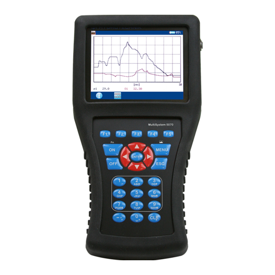
Page 119: Graphic Presentation In Display Menu
Displays scaling instead of current measurement values. • Channel p1 is displayed as blue line with crosses • Channel T1 is displayed as red line with diamonds • The current measured values are displayed beneath the graph Firmware Version 1.1 MultiSystem 5070... -
Page 120: Coupling Of Several Instruments
But please be aware that the parameters scanning rate, storage time and pretrig- ger must be programmed identically at all coupled measuring instruments. You can also couple MultiSystem 5070 instruments with MultiSystem 5060 Plus instruments. Connecting a measuring instrument electrically... -
Page 121: Serial Coupling
If you operate the coupled instruments in the “dynamic mode” (hardware filter switched off), all channels can be scanned with up to 10 kHz. Then the syn- chronisation delay between two devices is reduced to 0.1 ms. Firmware Version 1.1 MultiSystem 5070... -
Page 122: Parallel Coupling
Use of the MultiXtend Trigger For the coupling of more than two instruments we recommend the use of the MultiXtend Trigger (TKZ 316A-00-00.50). This simplifies the coupling and al- lows the use of the standard connection cables (TKZ 8824-F2-00.50). Firmware Version 1.1 MultiSystem 5070... -
Page 123: Programming Instruments
• The storage may not be stopped at any of the coupled instruments, other- wise a synchronisation becomes impossible • Avoid cyclic storage due to a possible triggering ahead of the desired time Firmware Version 1.1 MultiSystem 5070... -
Page 124: Transfer And Evaluate Measured Values
Connecting MultiXtend A and T You can use the MultiXtend A and T to connect additional analog sensors or thermocouples to the MultiSystem 5070. Their signals are digitalised by the MultiXtend and transmitted to the CAN input of the measuring instrument. The presentation, storage and evaluation of the measuring data is then done in the instrument. -
Page 125: Activate Can Bus
1 Open Connections menu: 2 Open CAN#1 CAN#2 dialog: 3 Select Interface: 4 Set setting to ACTIVE: 5 Toggle to input of the Baudrate: 6 Select desired baud rate: 7 Confirm changes and exit dialog: Firmware Version 1.1 MultiSystem 5070... -
Page 126: Program Can Channels
• Pressure sensor 0 – 200 bar at input 2 • Temperature sensor 0 – 60 °C at input 3 Program three special channels on the MultiSystem 5070: For example, channels 13 to 15. For each channel in the Calculation field, select MultiXtend. -
Page 127: Starting The Multixtend
MultiXtend must be started again. 1 Open Home menu: 2 Open Setting menu: 3 Open Unit menu: 4 Open Connections menu: 5 Open CAN#1 or open: 6 Select Start CANopen: 7 Start the MultiXtend: Firmware Version 1.1 MultiSystem 5070... -
Page 128: Viscosity-Compensated Volume Flow Rate Measuring
ISDS function (example: HySense QT 100). Use the integrated test point for the temperature measurement. The dialogs and functions described here are only available when a suitable tur- bine volume flow sensor is connected to the measuring instrument. Firmware Version 1.1 MultiSystem 5070... - Page 129 Open the dialog of the measuring channel that you want to use for volume flow measurement rate measurement. Highlight the entry Viscos.balance and press switch it to ACTIVE. Further options will be displayed: SAVE Stores the current sensor parameters in the database. Confirms input/saves change Firmware Version 1.1 MultiSystem 5070...
-
Page 130: Firmware Version 1.1 Multisystem
Highlight the next line, press and select the measuring channel, where the oil temperature is measured. Then highlight the item Oil parameter and press to select or program the oil being used. Firmware Version 1.1 MultiSystem 5070... - Page 131 To write a new oil to the database, select an empty entry (-) from the oil data- base. Press , highlight the parameters and enter the values. Then press to save the new oil. Press to delete the currently displayed oil from the database. Firmware Version 1.1 MultiSystem 5070...
- Page 132 The result of the calculation will be used at the channel for volume flow rate measurement to compensate the viscosity changes dependent on the temper- ature. You may also display and record this channel. Firmware Version 1.1 MultiSystem 5070...
-
Page 133: Reference For The Icons
Loading a saved configuration on page 44 Delete Configurations > Delete configurations Configurations Deleting a saved configuration on page 44 Oil condition Special applications > Oil condition Special applications on page 143 Firmware Version 1.1 MultiSystem 5070... - Page 134 Configure special channels (Ch11 ... Ch42) on page 69 Possible assignments of the special channels on page 70 Calculations with formulas on page 72 Settings > Channels > CAN channels channels CAN configuration on page 83 Firmware Version 1.1 MultiSystem 5070...
- Page 135 LAN/WLAN LAN/WLAN on page 88 Bluetooth Settings > Device > Connections > Bluetooth Bluetooth on page 89 COM #1 Settings > Device > Connections > COM #1 COM #1 on page 86 Firmware Version 1.1 MultiSystem 5070...
- Page 136 Reference for the icons HOLD Only permissible as softkey. “freezes” the measured values display. Firmware Version 1.1 MultiSystem 5070...
-
Page 137: Softkeys: Symbols/Text
Movement factors in the presentation type graph: Changes the step width in the spot and delta spot func- tion. Escape function: Leaves the dialog without saving. BACKSP Backspace function: Deletes the character next to the cursor. Firmware Version 1.1 MultiSystem 5070... - Page 138 Opens the selection for the current year. MONTH Opens the selection for the current month. Converts to decimal numbers. Converts to hexadecimal numbers. Selects all entries. Removes all selections. COL/SYM Opens the Display (symbols/colors) dialog. Firmware Version 1.1 MultiSystem 5070...
- Page 139 Measured value display, graphic display: Displays cur- rent measurement values instead of scaling. Confirms input/saves change INFO Displays information about the selected object. DISPLAY Displays the selected measurement. SETUP Opens the Setup recording dialog. SEARCH Starts the search. Firmware Version 1.1 MultiSystem 5070...
- Page 140 Saves data, e.g. sensor parameters. CORR Opens the editing function. DETAIL Special applications. EDIT Edits the current function. FILTER Opens the Filter overview dialog. SCAN Scans the CAN BUS for messages. Opens the selection for the current day. Firmware Version 1.1 MultiSystem 5070...
-
Page 141: Cleaning And Maintenance
This device is maintenance-free. However, it is still essential to have it recali- brated regularly. If the device is in continuous use, we recommend recalibrating it every 2 years. HYDROTECHNIK maintains a capable calibration laboratory. Please contact us: Firmware Version 1.1... -
Page 142: Repair
Manufacturer address and customer service Please contact the HYDROTECHNIK customer service department: HYDROTECHNIK GmbH Holzheimer Straße 94 D-65549 Limburg an der Lahn Tel.: +49 6431 4004 555... - Page 143 This submenu contains several functions that enhance the functionality of the MS 5070 or that are required for the operation of external devices: There is a detailed description of the menus in a separate document. Firmware Version 1.1 MultiSystem 5070...
Need help?
Do you have a question about the MultiSystem 5070 and is the answer not in the manual?
Questions and answers