Table of Contents
Advertisement
Quick Links
Advertisement
Table of Contents

Related Manuals for Metrohm 894 Professional CVS


Summary of Contents for Metrohm 894 Professional CVS
- Page 1 894 Professional CVS Manual 8.894.8001EN / 2017-08-15...
- Page 3 Metrohm AG CH-9100 Herisau Switzerland Phone +41 71 353 85 85 Fax +41 71 353 89 01 info@metrohm.com www.metrohm.com 894 Professional CVS Manual 8.894.8001EN / 2017-08-15...
- Page 4 Technical Communication Metrohm AG CH-9100 Herisau techcom@metrohm.com This documentation is protected by copyright. All rights reserved. This documentation has been prepared with great care. However, errors can never be entirely ruled out. Please send comments regarding possible errors to the address above.
-
Page 5: Table Of Contents
3.3.3 Installing FEP tubing .............. 33 Connecting instruments electrically ........40 3.4.1 Connecting the instrument to the power grid ......40 3.4.2 Connecting the 894 Professional CVS ........41 3.4.3 Connecting an 800 Dosino ............ 43 ■■■■■■■■ 894 Professional CVS... - Page 6 Replacing electrode cables ..........70 Adjusting the sample needle in the Sample Processor ... 71 Calibrator ................72 Relocating the 894 Professional CVS ........ 72 Quality management and qualification with Metrohm ... 74 7 Troubleshooting 894 Professional CVS ............75 Peripheral devices ...............
- Page 7 Table of contents Calibrator ................82 Stirrer ................... 82 9.10 Hardware ................83 9.11 Power connection ............... 83 9.12 Ambient temperature ............83 9.13 Reference conditions ............83 9.14 Housing data ............... 84 10 Accessories Index ■■■■■■■■ 894 Professional CVS...
- Page 8 ■■■■■■■■■■■■■■■■■■■■■■ Table of figures Table of figures Figure 1 894 Professional CVS front ..............7 Figure 2 894 Professional CVS rear ..............8 Figure 3 RDE measuring head - Overview ............10 Figure 4 Measuring head connector plate ............. 11 Figure 5 Measuring head insert ..............
- Page 9 Automated operation – Tubing setup – Adding rinsing solution and pumping out the waste solution ............63 Figure 44 Automated operation – Tubing configuration – Rinsing and waste solu- tions – Details 894 Professional CVS ..........64 Figure 45 Removing the measuring head ............67 Figure 46 Do not touch the drive disk .............
-
Page 11: Introduction
The additives can be quantitatively determined by means of CVS (Cyclic Voltammetric Stripping). The 894 Professional CVS is very compact in size and requires little space for operation. The measuring head can be removed from the instrument and put back in place again with a simple hand movement. -
Page 12: Intended Use
■■■■■■■■■■■■■■■■■■■■■■ 1.2 Intended use Intended use The 894 Professional CVS has been designed for use in the analysis of electroplating baths for the quantitative determination of organic addi- tives. The main fields of application are the following electroplating bath types: Acidic copper baths ■... -
Page 13: Symbols And Conventions
WARNING This symbol draws attention to a possible biological hazard. CAUTION This symbol draws attention to possible damage to instruments or instrument parts. NOTE This symbol highlights additional information and tips. ■■■■■■■■ 894 Professional CVS... -
Page 14: Safety Instructions
The electrical safety when working with the instrument is ensured as part of the international standard IEC 61010. WARNING Only personnel qualified by Metrohm are authorized to carry out service work on electronic components. WARNING Never open the housing of the instrument. The instrument could be damaged by this. -
Page 15: Personnel Safety
Wear protective glasses and work clothes suitable for laboratory work. WARNING Uncontrolled splashing of reagents Splashing reagents may result in injuries. Operate the 894 Professional CVS only with the measuring head in place and the measuring head arm lowered. ■■■■■■■■ 894 Professional CVS... -
Page 16: Tubing And Capillary Connections
The correct disposal of your old instrument will help to prevent negative effects on the environment and public health. More details about the disposal of your old instrument can be obtained from your local authorities, from waste disposal companies or from your local dealer. ■■■■■■■■ 894 Professional CVS... -
Page 17: Overview Of The Instrument
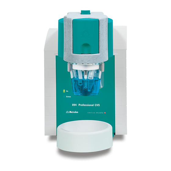
894 Professional CVS front "Status" LED "On" LED Continuously on: instrument ready for oper- Illuminated if the 894 Professional CVS is ation. Blinking regularly: instrument operat- connected to the power grid. ing. Blinking pattern "LED on a long time - off a short time - on a long time - off a short time, etc.": Standby potential is being... -
Page 18: Rear
For the deposition of solid materials that For positioning the drip pan. may be present. Rear Figure 2 894 Professional CVS rear Temperature sensor connector (Temp.) Type plates For connecting a temperature sensor of the With serial number. type Pt1000. Two B sockets, 2 mm. - Page 19 "Controller" connector MSB connectors (MSB 1 to 4) For connecting to a PC with the viva com- Metrohm Serial Bus. For connecting dosing puter software installed. Mini DIN, 8-pin. devices (800 Dosino) and Remote Boxes. Mini DIN, 8-pin. Power socket ■■■■■■■■...
-
Page 20: Rde Measuring Head
With openings for inserting electrodes and For connecting the RDE measuring head to tubing connections (see Figure 5, page 13). the connector plate of the measuring head arm (1- For connecting the electrodes and tubing (see Figure 4, page 11). ■■■■■■■■ 894 Professional CVS... -
Page 21: Measuring Head Connector Plate And Measuring Head Insert
For adding or aspirating solutions. Can be For adding or aspirating solutions. Can be connected to one of the openings 24 - 27 connected to one of the openings 24 - 27 (FEP tubing from 6.1829.070). (FEP tubing from 6.1829.070). ■■■■■■■■ 894 Professional CVS... - Page 22 CVS analyses. 13 M6 threaded opening (TAP) 14 - 30: see next figure With preinstalled tubing connection to threaded opening 17 - gas inlet. Not rele- vant for CVS analyses. ■■■■■■■■ 894 Professional CVS...
-
Page 23: Figure 5 Measuring Head Insert
18 Opening 19 Opening With preinstalled tubing connection to For tubing connection to threaded opening threaded opening 11 (OUT) - gas outlet. Not 8 (PURGE) - gas inlet. Not relevant for CVS relevant for CVS analyses. analyses. ■■■■■■■■ 894 Professional CVS... -
Page 24: Tubing Connector (Measuring Head Arm)
Tubing connector (measuring head arm) Nipple (N M6 threaded opening (3) Is connected to threaded openings TAP, For connecting tubing for aspirating or add- PURGE and N via the measuring head arm. ing solutions. Not relevant for CVS analyses. ■■■■■■■■ 894 Professional CVS... - Page 25 M6 threaded opening (1) M6 threaded opening (WASTE) For connecting tubing for aspirating or add- For connecting tubing for aspirating the ing solutions. measuring solution. M6 threaded opening (OUT) Not relevant for CVS analyses. ■■■■■■■■ 894 Professional CVS...
-
Page 26: Setting Up The Instrument
Preparing the measuring head The measuring head is supplied with a measuring head cover mounted in place. The measuring head must first be placed on the measuring head arm. Proceed as follows: 1 Tilt the measuring head arm up. ■■■■■■■■ 894 Professional CVS... -
Page 27: Figure 7 Do Not Touch The Drive Disk
The measuring head must snap into place with an audible click. Figure 8 Inserting the measuring head 3 Remove the stopper from the pipetting opening. ■■■■■■■■ 894 Professional CVS... -
Page 28: Figure 9 Removing The Stopper From The Pipetting Opening
4 Pull the slide lock on the top of the measuring head cover towards you and, at the same time, tilt the measuring head cover to an angle of approx. 45° and remove it. Figure 10 Removing the measuring head cover ■■■■■■■■ 894 Professional CVS... -
Page 29: Connecting The Gas Inlet
Insert the PTFE tubing for adding gas to the solution (6.1829.030) ■ through the opening (5-19). Pull the transparent inner tubing through as far as it will go. ■ Ensure that the green kink protection is protecting the entire piece ■ of tubing. ■■■■■■■■ 894 Professional CVS... -
Page 30: Figure 11 Inserting The Gas Inlet
3.2 Equipping the RDE measuring head Figure 11 Inserting the gas inlet Connect the tubing to the PURGE threaded opening and tighten it ■ hand-tight. Finally, tighten the tubing nipple using the wrench provided ■ (6.2739.000). ■■■■■■■■ 894 Professional CVS... -
Page 31: Preparing Electrodes And Inserting Them In The Rde Measuring Head
Connecting the gas inlet 3.2.2 Preparing electrodes and inserting them in the RDE measuring head The 894 Professional CVS uses the potentiostatic three-electrode principle. The following electrodes are used: Rotating disk electrode (RDE) as working electrode (WE) ■ Reference electrode (RE) ■... -
Page 32: Figure 13 Removing The Protective Cap From The Electrode Tip
Insert the working electrode into the opening (5-21) of the measur- ing head insert. Make sure that the pin on the lower part of the driving axle is posi- tioned in the opening (5-15) of the measuring head insert. ■■■■■■■■ 894 Professional CVS... -
Page 33: Figure 15 Working Electrode, Installed
■ wheel of the driving axle. Figure 16 Fastening the drive belt NOTE Make sure that the drive belt does not rub against the driving axle or surrounding components (tubing, cables, etc.). ■■■■■■■■ 894 Professional CVS... -
Page 34: Figure 17 Connecting The Working Electrode
Preparing and inserting the reference electrode Proceed as follows: 1 Remove the reference electrode from the storage vessel. The reference electrode that is part of the accessories is already filled with reference electrolyte (c(KCl) = 3 mol/L). ■■■■■■■■ 894 Professional CVS... -
Page 35: Figure 18 Assembling The Reference Electrode With The Electrolyte Vessel
Figure 18 Assembling the reference electrode with the electrolyte vessel 5 Rinse the installed reference electrode with ultrapure water. 6 Insert the installed reference electrode into the opening (5-20) of the measuring head insert. ■■■■■■■■ 894 Professional CVS... -
Page 36: Figure 19 Connecting A Reference Electrode
Plug the electrode cable with the RE marking on the plug onto the metal contact of the reference electrode. Figure 19 Connecting a reference electrode 3.2.2.3 Auxiliary electrode (AE) The auxiliary electrode (e.g. 6.0343.100) can be placed directly in the measuring head. ■■■■■■■■ 894 Professional CVS... -
Page 37: Figure 20 Connecting The Auxiliary Electrode
Observe the markings on the plugs, because the two cables must not be mixed up. Plug the electrode cable (4-7) with the AE marking on the plug onto the metal contact of the auxiliary electrode. Figure 20 Connecting the auxiliary electrode ■■■■■■■■ 894 Professional CVS... -
Page 38: Establishing The Tubing Connections
Installing the four-way micro dosing tip The four-way micro dosing tip (6.1824.000) can be used to connect the 894 Professional CVS to dosing devices of the type 800 Dosino and to dose auxiliary solutions and standard solutions automatically. Information on the electrical connection of dosing devices can be found in Chapter 3.4.3, page 43. -
Page 39: Figure 21 Inserting The Four-Way Micro Dosing Tip
Connecting the PTFE capillaries of the four-way micro dos- ing tip to a dosing unit Proceed as follows: 1 Screw the PTFE capillaries to the dosing units (port 1). Figure 22 Screwing a PTFE capillary to a dosing unit ■■■■■■■■ 894 Professional CVS... -
Page 40: Installing Capillaries
We recommend using the capillary cutter (6.2621.080) to obtain exactly flat edges of capillaries. Installing the capillary in the measuring head We recommend using a PEEK capillary (e.g. 6.1831.020) in the measuring head. Proceed as follows: ■■■■■■■■ 894 Professional CVS... -
Page 41: Figure 24 Inserting A Peek Capillary Into The Measuring Head
5 Cut the capillary to the desired length using the capillary cutter. In order to prevent diffusion between the solution in the capillary and the solution in the measuring vessel, make sure that the end of the capillary is positioned above the measuring solution. ■■■■■■■■ 894 Professional CVS... - Page 42 6.1803.020). Ensure that the capillary protrudes 1 to 2 mm from the tip of the pressure screw. 3 Push the capillary into the threaded opening of the adapter until it stops. 4 Only then start turning the pressure screw, while holding the capillary firmly in place. ■■■■■■■■ 894 Professional CVS...
-
Page 43: Installing Fep Tubing
Waste solution – aspirating via 843 Pump Station (see Figure 43, page ■ 63 and Figure 44, page 64) Auxiliary solutions (e.g. buffer, electrolyte, VMS, etc.) – adding via 800 ■ Dosino with dosing unit (see Figure 41, page 61) ■■■■■■■■ 894 Professional CVS... - Page 44 This does not apply to the tubing for draining the measuring solution; this tubing must touch the bottom of the measuring vessel. ■■■■■■■■ 894 Professional CVS...
-
Page 45: Figure 26 Inserting A Piece Of Fep Tubing Into The Measuring Head
(in the order 3, 2, WASTE, 1). Installing the measuring head cover The measuring head cover must be on the measuring head during deter- minations. Proceed as follows: ■■■■■■■■ 894 Professional CVS... -
Page 46: Figure 27 Installing The Measuring Head Cover
Fold back the measuring head cover and gently push it in place. The measuring head cover must snap into place with an audible click. 3 Insert the stopper (3-5) into the pipetting opening. ■■■■■■■■ 894 Professional CVS... -
Page 47: Figure 28 Inserting The Stopper In The Pipetting Opening
A bottle cap (6.1602.115) is required to connect a piece of FEP tubing to a rinsing canister. Figure 43, page 63 provides an overview of the tubing between the rinsing canister, 843 Pump Station and 894 Professional CVS. ■■■■■■■■ 894 Professional CVS... -
Page 48: Figure 29 Installing A Bottle Cap With Pieces Of Tubing On A Rinsing Canister
A five-way tubing connector (6.1828.020) is required to connect FEP tub- ing to a waste canister. Figure 43, page 63 provides an overview of the tubing between the waste canister, 843 Pump Station and 894 Professio- nal CVS. ■■■■■■■■ 894 Professional CVS... -
Page 49: Figure 30 Connecting The Five-Way Tubing Connector To A Waste Canister
In order to ensure that liquid is transported smoothly from and to the canisters, the canisters must not be air-tight. If necessary, loosen the screw caps a little. Connecting FEP tubing to a dosing unit with auxiliary solu- tion Proceed as follows: ■■■■■■■■ 894 Professional CVS... -
Page 50: Connecting Instruments Electrically
Unplug the power plug immediately if you suspect that moisture has ■ gotten inside the instrument. Only personnel who have been issued Metrohm qualification may ■ perform service and repair work on electrical and electronic parts. Connecting the power cord Accessories Power cord, three-core with IEC 60320 instrument plug type C13. -
Page 51: Connecting The 894 Professional Cvs
(IEC standard) to the protective ground (protection class I). 3.4.2 Connecting the 894 Professional CVS The 894 Professional CVS is connected to the PC with the supplied con- troller cable. Connecting the PC Proceed as follows: 1 Connect the controller cable (6.2151.000) to the "Controller"... - Page 52 2 Click on Yes. The following dialog window is displayed: 3 Change the suggested instrument name if required. 4 Confirm with OK. The instrument will be automatically listed in the device table of the Configuration program part. ■■■■■■■■ 894 Professional CVS...
-
Page 53: Connecting An 800 Dosino
You can connect up to four dosing devices of the type 800 Dosino directly to the 894 Professional CVS. As an alternative, you can connect the dos- ing devices via an 846 Dosing Interface, a sample changer or any other supported instrument that has MSB outputs. - Page 54 Initializing a dosing unit in viva Proceed as follows: 1 Select the 894 Professional CVS in the device table of the Configu- ration section of the program. 2 In the device table, click on the Edit button and select Initialize.
- Page 55 This ensures that functions in viva such as Prepare or Empty work properly. The lengths and diameters of the tubing connections in the measuring head arm can be found in Chapter 8.1, page 79. ■■■■■■■■ 894 Professional CVS...
- Page 56 5 Click on Yes if you are using the already configured dosing unit. The dosing unit will be automatically displayed in the Dosing units subwindow of the Configuration program part. NOTE Check the Tubing parameters and adapt them to the actual installation, if necessary. ■■■■■■■■ 894 Professional CVS...
-
Page 57: Start-Up
■■■■■■■■■■■■■■■■■■■■■■ 4 Start-up 4 Start-up The 894 Professional CVS is operated exclusively via the viva PC software. You can find information on operating viva in the online help and in the Tutorial CVS. Proceed as follows for the initial start-up of the 894 Professional CVS:... - Page 58 Chapter 6.7, page 72. In viva, proceed as follows: 1 Select the 894 Professional CVS in the device table of the Configu- ration section of the program. 2 In the device table, click on the Edit button and select Properties..
- Page 59 4 Click on Activate calibrator and then on OK. The set-to-work date of the calibrator and the calibrator's serial num- ber are displayed on the Calibrator tab after the dialog window has been closed and opened again. ■■■■■■■■ 894 Professional CVS...
- Page 60 The calibration certificate is available online. Go to http:// www.metrohm.com/com/Support/zertifikate/instrumentCertifi- and enter the serial number of the calibrator to down- cate.html load the certificate. 5 If required, adjust the settings on the Calibrator tab (e.g. Message or Action). ■■■■■■■■ 894 Professional CVS...
-
Page 61: System Configuration
■ Automated operation ■ The parts that are required in addition to the 894 Professional CVS and the CVS electrode kit are listed for each operating mode. Manual operation In manual operating mode, all solutions are added via the pipetting open- ing (5-22). -
Page 62: Semiautomated Operation
For the system configurations shown in the following figures, you will, depending on the application, need the brightener option (6.5339.500) in addition to the 894 Professional CVS (2.894.1210) and a CVS electrode kit (6.5339.0x0). 5.2.1 Connecting devices electrically... -
Page 63: Figure 35 Semiautomated Operation - Tubing Setup With Two Dosing Units
■■■■■■■■■■■■■■■■■■■■■■ 5 System configuration 6.1829.070 6.1805.120 6.1824.000 6.1808.000 + 6.1446.040 6.2055.110 6.1618.060 6.1805.100 6.1543.060 6.1608.070 6.1829.020 6.1805.530 6.1805.530 6.1602.190 2 x 6.1819.010 6.1608.070 Figure 35 Semiautomated operation – Tubing setup with two dosing units ■■■■■■■■ 894 Professional CVS... -
Page 64: Figure 36 Semiautomated Operation - Tubing Setup With Four Dosing Units
6.1808.000 + 6.1446.040 6.1618.060 6.1618.060 6.1805.100 6.1805.100 6.1543.060 6.1543.060 6.1608.070 6.1829.020 6.1805.530 6.2055.110 6.1805.530 6.1805.530 6.1805.530 6.1602.190 4 x 6.1819.010 6.2055.110 6.1618.060 6.1805.100 6.1543.060 6.1608.070 Figure 36 Semiautomated operation – Tubing setup with four dosing units ■■■■■■■■ 894 Professional CVS... -
Page 65: Figure 37 Semiautomated Operation - Tubing Setup - Details 894 Professional
■■■■■■■■■■■■■■■■■■■■■■ 5 System configuration 800 (1) ~ 0.5 cm Figure 37 Semiautomated operation – Tubing setup – Details 894 Pro- fessional CVS FEP tubing (tubing set 6.1829.070) Use the tubing with the long kink protec- tion. ■■■■■■■■ 894 Professional CVS... -
Page 66: Automated Operation
■■■■■■■■■■■■■■■■■■■■■■ 5.3 Automated operation Automated operation The 894 Professional CVS can be operated in conjunction with the follow- ing Sample Processors: 858 Professional Sample Processor ■ 919 IC Autosampler plus ■ 814 USB Sample Processor ■ 815 Robotic USB Sample Processor XL ■... -
Page 67: Figure 38 Automated Operation - Electrical Connections
■■■■■■■■■■■■■■■■■■■■■■ 5 System configuration 6.2151.000 6.2141.300 6.2151.000 6.2151.000 800 (1) 800 (3) 800 (2) 800 (4) Figure 38 Automated operation – Electrical connections ■■■■■■■■ 894 Professional CVS... -
Page 68: Establishing The Tubing Connections
Sample Processor details – Guide chain Figure 43 Automated operation – Tubing setup – Adding rins- ing solution and pumping out the waste solution Figure 44 Automated operation – Tubing configuration – Rins- ing and waste solutions – Details 894 Professional ■■■■■■■■ 894 Professional CVS... - Page 69 6.1803.020 (20 cm) 6.1803.020 (150 cm) + 2 x 6.2744.010 + 2 x 6.2744.010 6.1803.020 (60 cm) + 2 x 6.2744.010 6.1826.020 + 2 x 6.2744.160 6.2833.000 6.1835.050 Figure 39 Automated operation – Tubing setup – Overview ■■■■■■■■ 894 Professional CVS...
- Page 70 843 (2) 843 (1) 800 (1) ~ 0.5 cm Figure 40 Automated operation – Tubing setup – Details 894 Professio- nal CVS FEP tubing (6.1829.070 tubing set) Use the tubing with the long kink protec- tion. ■■■■■■■■ 894 Professional CVS...
- Page 71 ■■■■■■■■■■■■■■■■■■■■■■ 5 System configuration 6.2055.110 6.2055.110 843 (1) 6.1621.000 Figure 41 Automated operation – Tubing setup – 800 Dosino details ■■■■■■■■ 894 Professional CVS...
- Page 72 ■■■■■■■■■■■■■■■■■■■■■■ 5.3 Automated operation 800 (4) Figure 42 Automated operation – Tubing setup – 858 Professional Sample Processor details – Guide chain ■■■■■■■■ 894 Professional CVS...
-
Page 73: Figure 43 Automated Operation - Tubing Setup - Adding Rinsing Solution And Pumping Out The Waste Solution
5 System configuration 800 (1)/(2)/(3)/(4) 6.1828.020 6.1805.530 4 x 6.1820.010 6.1621.000 6.1805.530 6.1805.530 6.1805.530 6.1602.115 6.1829.070 6.1621.000 6.1819.110 Figure 43 Automated operation – Tubing setup – Adding rinsing solu- tion and pumping out the waste solution ■■■■■■■■ 894 Professional CVS... - Page 74 ~ 0.5 cm ~ 6.5 cm Figure 44 Automated operation – Tubing configuration – Rinsing and waste solutions – Details 894 Professional CVS FEP tubing (6.1829.070 tubing set) FEP tubing (6.1829.070 tubing set) Use the tubing with the long kink protec- Use the tubing with the short kink protec- tion.
-
Page 75: Operation And Maintenance
In such a case, contact Met- rohm Service. Spilled chemicals and solvents should be removed immediately. In particu- lar, the plug connections (particularly the power plug) should be protected from contamination. ■■■■■■■■ 894 Professional CVS... -
Page 76: Maintenance By Metrohm Service
Maintenance by Metrohm Service Maintenance of the instrument is best carried out as part of annual serv- ice, which is performed by specialist personnel from Metrohm. A shorter maintenance interval is recommended if you frequently work with caustic and corrosive chemicals. Metrohm Service offers every form of technical advice for maintenance and service of all Metrohm instruments. -
Page 77: Figure 45 Removing The Measuring Head
Observe the notes on maintenance and care in the electrode leaflet. CAUTION Do not apply pressure to the drive disk on the connector plate of the measuring head arm, as this could damage the stirrer motor. ■■■■■■■■ 894 Professional CVS... -
Page 78: Performing A Dummy Cell Test
1 Load the Dummy cell test method template in viva. 2 Plug the three electrode cables onto the contacts of the dummy cell (6.2813.050). Observe the correct assignment of the electrode cables (WE, RE and AE). ■■■■■■■■ 894 Professional CVS... -
Page 79: Figure 47 Dummy Cell Test - Ideal Curve Progression
At +2.0 V, the current should be +1.67 mA ± 0.33 mA. ■ Figure 47 Dummy cell test – Ideal curve progression 5 If the resulting curve is not consistent with this representation and the problems with the determinations persist, contact the local Met- rohm Service. ■■■■■■■■ 894 Professional CVS... -
Page 80: Replacing Electrode Cables
Make sure that the ellipsis-shaped recess on the cylinder is facing up when you insert the new cable set. This is important to ensure that the three electrodes are connected to the correct connectors inside the measuring instrument. ■■■■■■■■ 894 Professional CVS... -
Page 81: Adjusting The Sample Needle In The Sample Processor
The work position settings must be defined in viva. If required, adjust the sample needle in viva as shown in the figure: max. 0.5 mm Figure 49 Adjusting the sample needle in the Sample Processor ■■■■■■■■ 894 Professional CVS... -
Page 82: Calibrator
In this way, the 894 Profes- sional CVS automatically recalibrates itself before each measurement. When the 894 Professional CVS is started up, a prompt to activate the cal- ibrator appears (see "Activating the calibrator", page 48). The automatic adjustment is active starting with this activation time. - Page 83 Lower the measuring head arm again. 5 Hold the instrument with one hand on the drip pan holder and with the other hand at the rear of the measuring head arm and relocate the instrument. ■■■■■■■■ 894 Professional CVS...
-
Page 84: Quality Management And Qualification With Metrohm
Metrohm offers you comprehensive support in implementing quality man- agement measures for instruments and software. Qualification Please contact your local Metrohm representative for support in qualifica- tion of instruments and software. The Installation Qualification (IQ) and Operational Qualification (OQ) are offered by Metrohm represen- tatives as a service. -
Page 85: Troubleshooting
■■■■■■■■■■■■■■■■■■■■■■ 7 Troubleshooting 7 Troubleshooting 894 Professional CVS Problem Cause Remedy An electrode cable The cable has accidentally Replace the electrode cable set . has broken. been jammed in the meas- uring head cover or a cable contact has been kinked. - Page 86 ■■■■■■■■■■■■■■■■■■■■■■ 7.1 894 Professional CVS Problem Cause Remedy The measuring vessel con- Check the fill level in the measuring vessel and tains too little solution or is add solution if necessary. empty. The electrode tip of An incorrect potential has Check the reference electrode;...
-
Page 87: Peripheral Devices
The 800 Dosino can- The connection between Check the cable connections. ■ not be actuated by the 800 Dosino and the Disconnect the 894 Professional CVS from ■ the 894 Professional 894 Professional CVS is the power grid and connect it again. CVS. - Page 88 Check whether the dosing drive is correctly ■ rectly. seated. Disconnect the 894 Professional CVS from ■ the power grid and connect it again. Contact Metrohm Service if necessary. ■ The membrane The cables are not or not Connect the cables as described in .
-
Page 89: Appendix
A standby potential is being applied to the "LED on a long electrodes. Do not remove the measuring head time - off a short or the electrode cables in this instrument status. time - on a long time - off a short time…" ■■■■■■■■ 894 Professional CVS... -
Page 90: Technical Specifications
Sweep potential ±5.0 V range Current measuring +200 pA - +224 mA ranges (Not all ranges are available in all measuring modes.) > 800 kHz Bandwidth Rise time / fall 300 ns time Noise 5 pA typical ■■■■■■■■ 894 Professional CVS... -
Page 91: Galvanostat
±(0.2% of the current +0.2% of the current measuring range) Current measured ±(0.2% of the current +0.2% of the current measuring range) ±(0.2% of the potential ± 1 mV) Potential applied Potential meas- ±(0.2% of the potential ± 1 mV) ured ■■■■■■■■ 894 Professional CVS... -
Page 92: Resolution
178 Ω R178 1900 Ω R1.9k 18000 Ω R18k 180000 Ω R180k 1800000 Ω R1.8M 18000000 Ω R18M Validity of the cer- Two years after activation tification Stirrer Stirring rate 200 - 3,000 min Stability ±2% ■■■■■■■■ 894 Professional CVS... -
Page 93: Hardware
Storage –40 - +70 °C Transport –40 - +70 °C 9.13 Reference conditions Ambient tempera- +25 °C (±3 °C) ture ≤ 60% Relative humidity Operating temper- Instrument in operation at least 30 min ature status ■■■■■■■■ 894 Professional CVS... -
Page 94: Housing Data
Weight 7,400 g Dimensions with measuring head and drip pan Width 188 mm 322 mm Height Depth 452 mm Material of hous- Cover PP with flame retardation for fire class UL94 V-0 Base Steel sheet, coated ■■■■■■■■ 894 Professional CVS... -
Page 95: 10 Accessories
The PDF file with the accessories data will be created. NOTE When you receive your new instrument, we recommend downloading the accessories list from the Internet, printing it out and keeping it together with the manual for reference purposes. ■■■■■■■■ 894 Professional CVS... -
Page 96: Index
Manual ....... 51 Troubleshooting ....78 Electrostatic charge ....5 Semiautomated ....52 Tubing setup ...... 37 MSB device 894 Professional CVS Connect ......43 Start-up ......47 FEP tubing Troubleshooting ....75 See also "Tubing" ....33 Four-way micro dosing tip Operational qualification .. - Page 97 Automated system ..... 58 843 Pump Station ....37 Connect ......24 Semiautomated system ..52 Rinsing canister ....37 Insert ........22 Tubing diameter Waste canister ....38 Prepare ....... 22 Measuring head arm ..79 ■■■■■■■■ 894 Professional CVS...
Need help?
Do you have a question about the 894 Professional CVS and is the answer not in the manual?
Questions and answers