Table of Contents

Related Manuals for Falcon FE2M


Summary of Contents for Falcon FE2M
- Page 1 User, installation, and servicing instructions CONVECTION OVENS FE2M, FE3D, FE4D, FE4M Read these instructions before use. DATE PURCHASED: MODEL NUMBER: SERIAL NUMBER: DEALER: SERVICE PROVIDER: T101063 Rev No 2 Published: 06/06/22...
- Page 2 Dear Customer Thank you for choosing Falcon Foodservice Equipment. This manual can be downloaded from www.falconfoodservice.com or scan here: IMPORTANT: Please keep this manual for future reference. Original Instructions Falcon Foodservice Equipment HEAD OFFICE Wallace View, Hillfoots Road, Stirling. FK9 5PY. Scotland.
- Page 3 SYMBOLS SCREWDRIVER SPANNER COOKING OIL GREASE WARNING SPARK IGNITION FLAME VIEWPORT ALLEN KEY IGNITER C SPANNER REMOVE DEVICE PLUG REMOVER...
- Page 4 • This appliance may be discoloured due to testing. • These instructions are only valid if the country code appears on the appliance. If the code does not appear on the appliance, refer to the technical instructions for adapting the appliance to the conditions for use in that country.
- Page 5 Training and competence To help ensure the safe use of this appliance there is a requirement for you to provide whatever information, instruction, training, and supervision as is necessary to ensure, so far as is reasonably practicable, the health and safety of all users. For further help and information on training and competence we would refer you the Health and Safety Executive website;...
-
Page 6: Table Of Contents
CONTENTS APPLIANCE INFORMATION ..................8 OPERATION ......................9 COMPONENT PARTS & CONTROLS ..............9 USING THE APPLIANCE – FE2M & FE4M ............13 USING THE APPLIANCE – FE3D & FE4D ............13 CLEANING AND MAINTENANCE ................16 CLEANING ......................17 SPECIFICATION ...................... - Page 7 7.18 CIRCUIT DIAGRAMS ..................35 7.19 WIRING DIAGRAMS ..................38 ACCESSORIES ......................42 FAULT FINDING ...................... 43 10.0 SPARE PARTS ......................44 11.0 SERVICE INFORMATION ..................45...
-
Page 8: Appliance Information
1.0 APPLIANCE INFORMATION The data plate shows model information including relevant UKCA/CE-mark certification reference based on compliance with the Product Safety and Metrology Regulations/GAR, and/or Electrical Safety (LVD) and Electromagnetic Compatibility (EMC) Regulations/Directives for the Countries as stated. A - Serial No B - Model No C - Gas Category D - Gas Supply Pressure... -
Page 9: Operation
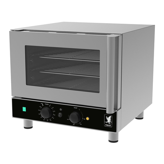
2.0 OPERATION 2.1 COMPONENT PARTS & CONTROLS 2.1.1 FE2M Door On/Off switch (Green) Control Panel Oven shelf support Oven heat neon (Amber) Oven shelf Oven temperature control Oven Light Switch Oven timer control... - Page 10 2.1.2 FE3D Door Oven timer control Control Panel Oven timer display Oven temperature control Oven shelf support Oven temperature display Oven shelf...
- Page 11 2.1.3 FE4M Door On/Off switch (Green) Control Panel Oven shelf support Oven heat neon (Amber) Oven shelf Oven temperature control Oven Light switch Oven timer control...
- Page 12 2.1.4 FE4D Door Oven timer display Control Panel Oven timer control Oven temperature control Oven shelf support Oven temperature display Oven shelf...
-
Page 13: Using The Appliance - Fe2M & Fe4M
2.2 USING THE APPLIANCE – FE2M & FE4M 2.2.1 Plug the appliance into a 13A socket. Switch on the mains supply. 2.2.2 Set timer control to MAN position, press the ON/OFF switch to the ON position. The fan will rotate. - Page 14 PRESET PROGRAMS 2.3.10 The appliance has 5 pre-set programs & 5 user-defined program options. Meat portions Danish Pastries / Croissants - Cook from Stage 1 frozen Temperature 220°C Stage 1 Convection Only 8 mins Temperature 160°C Stage 2 Convection Only 5 mins Convection with Steam 5 sec burst Stage 2...
- Page 15 The various models are designed to take the following tray sizes: Model Wire rack Wire rack 1/1 Gastronorm Shelf ½ sheet Quantity width Gastronorm Positions FE2M 460 mm On wire Directly in shelf racks hanger runners FE3D 460 mm On wire Directly in shelf racks...
-
Page 16: Cleaning And Maintenance
3.0 CLEANING AND MAINTENANCE BEFORE ATTEMPTING ANY MAINTENANCE, ISOLATE THE APPLIANCE AT THE MAIN SWITCH AND TAKE STEPS TO ENSURE THAT IT IS NOT INADVERTENTLY SWITCHED ON. MAINTENANCE CHECK Regular servicing of the appliance should be undertaken to ensure correct operation, it is functioning as intended, and safe to use. -
Page 17: Cleaning
Clean and wipe dry as in 3.1.8 above. To close, gently lift & push inner panel back towards door frame, & lower on to locating pins. Please refer to falconfoodservice.com/info-centre/falcon-tv/cleaning guides/cleaning-guides-ovens-and-hobs for a detailed instructional guide & video. -
Page 18: Specification
4.0 SPECIFICATION 4.1 APPLIANCE WEIGHT TABLE APPLIANCE UNIT WEIGHT (kg) PACKED WEIGHT (kg) FE2M 41kg 50kg FE3D 48kg 57kg FE4D 53kg 68kg FE4M 55kg 70kg 4.2 TECHNICAL DATA TABLE FE2M CURRENT POWER ACTUAL (A) @ PHASE MIN (A) @ 230V... -
Page 19: Dimensions / Connection Locations
5.0 DIMENSIONS / CONNECTION LOCATIONS FE2M Electrical connection location FE3D Electrical connection location... - Page 20 FE4D & FE4M Electrical connection location...
-
Page 21: Installation
To reduce risk of liquid burns and spillages from using the oven it is recommended that the top shelf height should be below 1.60m from floor level. Fitting the appliance on a Falcon stand or a standard height work surface will ensure this recommendation is met. -
Page 22: Electric Supply & Connection
6.3 ELECTRIC SUPPLY & CONNECTION Electrical Safety and Advice Regarding Supplementary Electrical Protection Commercial kitchens and foodservice areas are environments where electrical appliances may be located close to liquids or operate in and around damp conditions or where restricted movement for installation and service is evident. -
Page 23: Connecting To Water Supply
The ejected steam is absorbed by the food and appliance has no drain connection. Water pressure for the water solenoid valve fitted within the appliance at the water inlet must not exceed 10bar (1000 kPa). 6.5 FE2M & FE4M COMMISSIONING Refer to section for operation. If safety thermostat is activated, refer to section 7.13... -
Page 24: Fe3D & Fe4D Commissioning
6.6 FE3D & FE4D COMMISSIONING Refer to section 2.0 for operation. If safety thermostat is activated, refer to section 7.13 to reset it. Carry out the following operation: 6.6.1 Turn mains power supply on. “PRE” for 5 seconds, then temperature display shows “MAN” 6.6.2 Time display flashes 6.6.3 Press temperature control knob to select “MAN”, rotate to “200”... -
Page 25: Servicing
For internal connection, outer sheathing must be stripped 140mm from cable end. The Live and Neutral conductors must be trimmed so that earth conductor is longer by 50mm. Pass inlet cable through rear panel cord grip and ensure cable is routed without leaving excessive free length inside unit. 7.1 FE2M AND FE3D CONTROL PANEL REMOVAL... -
Page 26: Fe4M And Fe4D Control Panel Removal
7.2 FE4M AND FE4D CONTROL PANEL REMOVAL 7.3 BACK PANEL AND OUTER WRAP REMOVAL... -
Page 27: Door Removal
7.4 DOOR REMOVAL 7.5 DOOR HANDLE REMOVAL... -
Page 28: Contactor / Relay / Buzzer Removal
7.6 CONTACTOR / RELAY / BUZZER REMOVAL 7.7 HEATING ELEMENTS REMOVAL Note: The element can be removed from inside the cavity, without removing rear panel (image 1 above). Remove element screws (images 2 & 3), carefully withdraw element and disconnect wires. -
Page 29: Fan Impellor Removal
Note: The fan impellor fixing nut has reverse thread. Turn clockwise to unscrew. Turn anti-clockwise to tighten. FE2M, FE4M and FE4D – unidirectional fan Note: The impellor spacer on the fan motor shaft at the rear of the impellor must be fitted with the wide flange against the impellor rear surface. -
Page 30: Fan Motor Removal
7.9 FAN MOTOR REMOVAL 7.10 FE2M AND FE4M TIMER REMOVAL... -
Page 31: Safety Thermostat Removal
7.11 FE2M AND FE4M OPERATING THERMOSTAT REMOVAL 7.12 SAFETY THERMOSTAT REMOVAL... -
Page 32: Safety Thermostat Reset
7.13 SAFETY THERMOSTAT RESET 7.14 FE3D AND FE4D TEMPERATURE SENSOR REMOVAL 7.15 NEON REMOVAL... -
Page 33: Led Light Strip Removal
7.16 LED LIGHT STRIP REMOVAL Remove contact switch and disconnect LED wires from connector. Pull wires through door frame. Ensure correct wire & switch polarity 7.17 PROXIMITY SENSOR AND LED CONTACT REMOVAL LED contact Proximity sensor Disconnect switch wires from terminal block. Ensure correct polarity of LED contact wires. -
Page 34: Water Solenoid Valve And Steam Injection Pipes
7.18 WATER SOLENOID VALVE AND STEAM INJECTION PIPES The solenoid valve has a detachable inlet filter 7.19 POWER CABLE REPLACEMENT ANY REPLACEMENT SUPPLY CABLE MUST BE 1.5MM², CORD CODE DESIGNATION 245 IEC 57 (CENELEC H05 RN-F). CONNECT BROWN – L, BLUE –... -
Page 35: Circuit Diagrams
7.20 CIRCUIT DIAGRAMS 7.20.1 FE2M/FE4M Circuit Diagram... - Page 36 7.20.2 FE3D Circuit Diagram...
- Page 37 7.20.3 FE4D Circuit Diagram...
-
Page 38: Wiring Diagrams
7.21 WIRING DIAGRAMS 7.21.1 FE2M Wiring Diagram... - Page 39 7.21.2 FE3D Wiring Diagram...
- Page 40 7.21.3 FE4M Wiring Diagram...
- Page 41 7.21.4 FE4D Wiring Diagram...
-
Page 42: Accessories
8.0 ACCESSORIES 8.1 CONNECTED KITCHEN CLOUD DATA TRANSFER For FE3D and FE4D models with IOT option Connected Kitchen is subscription service provided by Koolzone Ltd. This option provides real time data from a Cloud based network. Oven supplied with this option is IOT ready and requires some additional steps from Koolzone to enable. -
Page 43: Fault Finding
9.0 FAULT FINDING FAULT POSSIBLE CAUSES REMEDY USER *ENG Replace fuse ✓ No Power Fuse in plug blown If fuse blows again ✓ Safety thermostat Reset thermostat ✓ tripped (refer to section 7.13) Safety thermostat trips Thermostat faulty Replace faulty ✓... -
Page 44: Spare Parts
10.0 SPARE PARTS FE2M, FE4M FE3D, FE4D Wire rack – 460mm wide - (FE2M) Wire rack – 460mm wide – (FE3D) Wire rack – 525mm wide – (FE4M) Wire rack – 525mm wide – (FE4D) Temperature control knob Temperature control knob... -
Page 45: Service Information
11.0 SERVICE INFORMATION It is recommended to have a maintenance contract with a local service provider. SERVICELINE CONTACT: (UK only) Phone: +441438 363 000 Warranty Policy Shortlist For our warranty policy please go to www.falconfoodservice.com...
Need help?
Do you have a question about the FE2M and is the answer not in the manual?
Questions and answers