jotron Tron TR20 GMDSS User Manual
Hide thumbs
Also See for Tron TR20 GMDSS:
- Technical handbook (40 pages) ,
- User manual (50 pages) ,
- User manual (52 pages)
Table of Contents
Advertisement
Quick Links
Advertisement
Table of Contents
Troubleshooting

Related Manuals for jotron Tron TR20 GMDSS


Summary of Contents for jotron Tron TR20 GMDSS
- Page 1 USERS MANUAL Tron TR20 GMDSS www.jotron.com...
- Page 2 Amendment Records Amend- Date Page(s) Vers. Reason for change ment no 10.09.03 EM4038 04.03.04 1-5, 8,10 EM4197 03.10.06 56 total CN 05309 18.04.07 Total: 56 New company name and logo 27.06.07 Total: 52 New antenna Removed PLUS 03.02.09 44 and 45 Updated text 03.03.09...
- Page 3 EC Declaration of Conformity, available at www.jotron.com Read this Users Manual fully to familiarise yourself with the equipments functions and facilities. Abbreviations and definitions CLOCK A precisely spaced, stable train of pulses generated within an electronic sys- tem to synchronize the timing of digital operations within the system.
- Page 4 International Telecommunication Union. Light Emitting Diode. SubMiniature version A connector Triple Watch. Receiver altering between three different channels. Very High Frequency -A set of frequencies in the MHz region. VSWR Voltage standing wave ratio 80078_UM_TR20_N...
- Page 5 Jotron AS reserves the right to make changes without further notice to any products or modules described herein to improve reliability, function or design. Jotron AS does not assume any liability arising out of the ap- plication or use of the described product.
-
Page 6: Table Of Contents
TABLE OF CONTENTS General description Introduction Features Licensing Getting started Technical specification General Receiver Transmitter Charger Functional description Radio unit Antenna Battery removal and replacement Primary battery 3.4.1 Description 3.4.1.1 When to change battery Secondary battery and charger 3.5.1 Using the nimh battery 3.5.2... - Page 7 Operating instructions Configuring the TR20 Menu flowchart 5.2.1 Standard screen 5.2.2 Key lock Function keys Channel 16 Main menu 5.5.1 Contrast 5.5.2 Single / DW / TW 5.5.3 Key tone 5.5.4 Info 5.5.5 Battery selection Maintenance and troubleshooting How to take care of your TR20...
- Page 8 BATTERY SAFETY DATA SHEET (Form: EEC directive 91/155) (2) SAFETY ADVICE Keep out of reach from children. Keep container dry. In case of contact with eyes, rinse immediately with plenty of water and seek medical advice. In case of fire, use D type extinguishers. Never use water.
- Page 9 Special exposure hazards Generation of chlorine, sulfur dioxide, disulfur dichloride during thermal de- composition. Special protective equipment Use protective working boots, rubber apron and safety glasses with side shields. INSTRUCTIONS FOR KEEPING THE RA- DIO LOG AND THE RADIO OPERATORS OBLIGATION ACCORDING TO NATIONAL AND INTERNATIONAL REGULATION.
- Page 10 Test and maintenance record DATE N/T/B SIGN INSP N= New EPIRB installed, T= Test, B= New battery 80078_UM_TR20_N...
- Page 11 GUIDANCE ON DISTRESS ALERTS on VHF without DSC 80078_UM_TR20_N...
- Page 12 Write down the distress message. Speak slowly and distinctly. Alfa Papa Bravo Quebec Charlie Romeo Delta Sierra Echo Tango Foxtrot Uniform Golf Victor Hotel Whiskey India X-ray Juliett Yankee Kilo Zulu Lima Æ Ægir Mike Ø Ørnulf November Å...
-
Page 13: General Description
GENERAL DESCRIPTION INTRODUCTION Tron TR20 GMDSS (hereafter named as TR20) is specially designed for GMDSS applications. It confirms to ETS 300 225 standard and is waterproof to 1 meter. The housing is made from glass-reinforced polycarbonate in a highly visible colour. -
Page 14: Licensing
TR20 is equipped with a high contrast graphical display with built in backlight for clear indication of the radios settings. Service Handheld VHF service is available through the Jotron AS worldwide service network. See details on www.jotron.com. LICENSING Prior to use please check your national requirements for the operators of VHF radios and also that your radio will conform to local regulations before use. -
Page 15: Technical Specification
TECHNICAL SPECIFICATION GENERAL Frequency range: 154 – 163 MHz Channel spacing: 25kHz Operating temperature range: –20 to +55°C. Battery life: > 12 hours (Lithium battery, 2W power output, 10-10-80 @ -20ºC). > 11 hours (1500mAh NiMH battery, 5W power output, 5-5-90 @ +20ºC). -
Page 16: Functional Description
FUNCTIONAL DESCRIPTION RADIO UNIT PTT (Push To Talk) Menu Channel High / Low power Channel 16 Battery release ON / OFF Down Squelch Enter DW/TW Antenna Figure 3.1 Location of controls and facilities of the TR20 80078_UM_TR20_N... -
Page 17: Antenna
ANTENNA The antenna for TR20 is fitted with a standard SMA connector. A remote antenna can be connected for fixed applications. BATTERY REMOVAL AND REPLACEMENT To release the battery, press both battery release clips and gently pull the battery away from the radio. -
Page 18: Secondary Battery And Charger
To prevent the possibility of being in an emergency situation with a TR20 equipped with a used battery, we strongly recommend storing an extra bat- tery, in lifeboats and rafts. Store this battery without breaking the sealing. Special care The primary battery is of a high-energy lithium type, and some precautions must be taken. -
Page 19: Battery Endurance
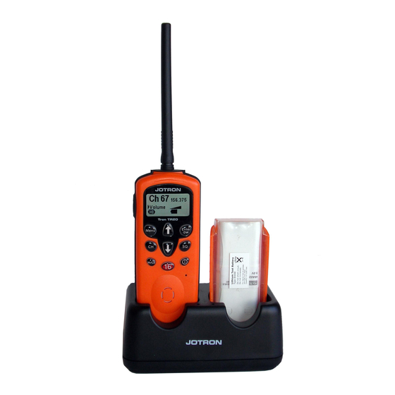
The first battery will then be trickle charged to keep it fully charged. The charger will charge a fully discharged battery in approx. 3.5 hours. Figure 3.6.2 TR20 and single battery in charger. -
Page 20: Installation
INSTALLATION • Connect the antenna before use and charge the battery fully before connecting to the equipment. • Follow this manuals menu selection and set the battery option being used on the equipment to ensure the battery state indicator gives a true reading. -
Page 21: Menu Flowchart
MENU FLOWCHART Menu Hi/Lo Enter/TW Receive 80078_UM_TR20_N... -
Page 22: Standard Screen
5.2.1 STANDARD SCREEN This is the standard/default screen for the TR20. The display returns to this mode after a break of more than 10 sec. In this mode the arrow buttons (2 & 9) adjusts the volume and the display gives a graphical volume indication. -
Page 23: Function Keys
FUNCTION KEYS Channel selection - CH To select the working channel, press the button “CH”(4). The channel is selected by pressing the arrow but- tons (2 & 9). Squelch - SQ To adjust the squelch level, press the button “SQ”(10). The level is adjusted by pressing the arrow buttons (2 &... - Page 24 CHANNEL 16 By pressing the red “16”(6) key, the TR20 will enter channel 16. When on channel 16, PTT will function even if the key lock is enabled. Default display on TR20 during transmit. When the TR20 receive a signal the symbol “RX”...
-
Page 25: Main Menu
MAIN MENU When the “Menu”(3) key is pressed the operator has access to the main menu. The menu will scroll when pressing the arrow keys (2 & 9). When the arrow is pointing at the required parameter, press enter (11) to select. -
Page 26: Single / Dw / Tw
5.5.2 SINGLE / DW / TW This feature enables TR20 to check for signals at one, two or three channels simultaneously. NOTE! The receiver power consumption will increase using DW and TW. Single means normal operation at one channel (the working channel). - Page 27 The working channel will then be displayed with large figures in the left part of the display, and channel 16 in the right part of the display. DW will be indicated in the lower right corner of the display.
- Page 28 Press the Menu (3) Key and select Single/DW/TW Use the arrow keys (2 & 9) to move the cursor to TW, and press Enter (11). Press Menu (3) to return to the main display. The working channel will then be...
-
Page 29: Key Tone
Note! The radio is not able to transmit when it is set to double or triple watch. To transmit, DW/TW has to be turned off by pressing the “Enter”(11) key. However, if channel 16 is selected it is always possible to transmit, regardless of the DW/TW setting. - Page 30 80078_UM_TR20_N...
-
Page 31: Maintenance And Troubleshooting
MAINTENANCE AND TROUBLESHOOTING HOW TO TAKE CARE OF YOUR TR20 TR20 is constructed to endure the rough maritime environment. Still the life is dependent on taking care of the equipment. It is a good practice to regu- larly inspect and test the equipment to detect error symptoms and prevent more serious problems. -
Page 32: Cleaning Of Dirt And Oil
Your radio should seldom require service or repair. Warranty time: 2 years from factory. All goods sold by the Jotron AS are warranted to be free from defect in work- manship and material for the period of twenty-four (24) months from the date... -
Page 33: Guide To Troubleshooting
IMPORTANT! The TR20 is a sealed waterproof radio and there are no user serviceable parts inside. It must never be opened, except by authorised Jotron AS agents. Unauthorised disassembly will invalidate the warranty. See the next chapter for failure diagnosis. This may be of help when dis- cussing problems with a Jotron AS agent. - Page 34 Problem Possible causes Possible solutions E1 is indicated on the Frequency synthesizer a) Try a reset by display. is out of lock. switching power OFF. b) Failure in frequency synthesizer. An aut- horised agent must service the unit. E2 is indicated on the...
-
Page 35: Maritime Vhf Channels
MARITIME VHF CHANNELS Channel Int. RX USA RX CAN RX GMDSS channels Designators (TR20 only) 156.000 156.000 156.000 156.025 (*1) 160.625 156.025 160.625 156.050 160.650 156.050 160.650 156.075 160.675 156.075 160.675 156.100 (*1) 160.700 156.100 160.700 156.125 (*1) 160.725 156.125... - Page 36 162.000 162.000 157.425 157.425 157.425 WX01 162.550 WX02 162.400 WX03 162.475 WX04 162.425 WX05 162.450 WX06 162.500 WX07 162.525 (*1) These channels are prohibited to transmit on in the USA. The Jotron agent can insert additionally 20 national channels. 80078_UM_TR20_N...
-
Page 37: Practical Use, Vhf Transmission Range
PRACTICAL USE, VHF TRANSMISSION RANGE The range of VHF communications is limited to ‘line of sight’, because the VHF radio waves are travelling in straight lines. A higher position of the trans- ceiver will then increase the coverage. This applies both to the receiving and transmitting end. -
Page 38: Spare Parts And Accessories
SPARE PARTS AND ACCESSORIES Description • 99930 Tron TR-20 GMDSS, transceiver only • 80060 Lithium battery, not rechargeable. • 80059 NiMH 7.2V, 1500mAh rechargeable battery pack • 99920 Dual slot fast charger for 80059 batteries. • 80080 Mains adapter for 99920 EURO style •... -
Page 39: Service Agents
SERVICE AGENTS Please look at www.jotron.com for Marine Service Agents. Jotron Group subsidiary companies: Jotron UK Ltd. Cramlington NE23 1LA United Kingdom +44 1670 712000 +44 1670 590265 E-mail: sales@jotron.com Jotron Asia Pte. Ltd. Changi Logistics Center 19 Loyang Way #04-26... - Page 40 www.jotron.com...
Need help?
Do you have a question about the Tron TR20 GMDSS and is the answer not in the manual?
Questions and answers