jotron TRON TR20 GMDSS User Manual
Hide thumbs
Also See for TRON TR20 GMDSS:
- Technical handbook (40 pages) ,
- User manual (50 pages) ,
- User manual (40 pages)
Table of Contents
Advertisement
Advertisement
Table of Contents
Troubleshooting

Related Manuals for jotron TRON TR20 GMDSS


Summary of Contents for jotron TRON TR20 GMDSS
- Page 1 80078_UM_ TR20_ I...
- Page 2 EC Declarations of Conformity, available at www.jotron.com Read this Users Manual fully to familiarise yourself with the equipments functions and facilities. Abbreviations and definitions CLOCK A precisely spaced, stable train of pulses generated within an electronic system to synchronize the timing of digital operations within the system.
- Page 3 IP rating Joint factor (to indicate the waterproofing of the equipment) International Telecommunication Union. Light Emitting Diode. SubMiniature version A connector Triple Watch. Receiver altering between three different channels. Very High Frequency -A set of frequencies in the MHz region. VSWR Voltage standing wave ratio 80078_UM_ TR20_ I...
- Page 4 Amendment Record REASON AMENDMENT INCORP. DATE PAGE(S) VERSION CHANGE 10.09.03 EM4038 04.03.04 1-5, 8,10 EM4197 03.10.06 56 total CN 05309 18.04.07 Total: 56 company name & logo New antenna 27.06.07 Total: 52 Removed PLUS Updated text 03.02.09 80078_UM_ TR20_ I...
- Page 5 Jotron AS reserves the right to make changes without further notice to any products or modules described herein to improve reliability, function or design. Jotron AS does not assume any liability arising out of the application or use of the described product.
-
Page 6: Table Of Contents
LIST OF CONTENTS 1 GENERAL DESCRIPTION ................14 ....................14 NTRODUCTION ....................... 15 EATURES ...................... 16 ICENSING ..................17 ETTING STARTED 2 TECHNICAL SPECIFICATION ..............18 ......................18 ENERAL ....................... 19 ECEIVER ....................19 RANSMITTER ....................... 19 HARGER FUNCTIONAL DESCRIPTION ..............20 .................... - Page 7 4 INSTALLATION ..................... 27 5 OPERATING INSTRUCTIONS ..............28 TR20 ................28 ONFIGURING THE ..................29 LOWCHART 5.2.1 Standard screen ..................30 5.2.2 Key Lock ....................31 ....................31 UNCTION KEYS 16 ....................33 HANNEL ....................34 AIN MENU 5.5.1 Contrast ....................
- Page 8 8 PRACTICAL USE, VHF TRANSMISSION RANGE ........49 9 SPARE PARTS AND ACCESSORIES ............50 10 SERVICE AGENTS ..................51 80078_UM_ TR20_ I...
- Page 9 BATTERY SAFETY DATA SHEET (Form: EEC directive 91/155) (2) SAFETY ADVICE Keep out of reach from children. Keep container dry. In case of contact with eyes, rinse immediately with plenty of water and seek medical advice. In case of fire, use D type extinguishers. Never use water. In case of accident or if you feel unwell, seek medical advice immediately (show the label where possible).
- Page 10 Special exposure hazards Generation of chlorine, sulfur dioxide, disulfur dichloride during thermal decomposition. Special protective equipment Use protective working boots, rubber apron and safety glasses with side shields. INSTRUCTIONS FOR KEEPING THE RADIO LOG AND THE RADIO OPERATORS OBLIGATION ACCORDING TO NATIONAL AND INTERNATIONAL REGULATION. 1.
- Page 11 TEST AND MAINTENANCE RECORD DATE N/T/B SIGN INSP N=NEW RADIO INSTALLED, T=TEST, B=NEW BATTERY 80078_UM_ TR20_ I...
- Page 12 EXAMPLE OF DISTRESS PROCEDURE FOR MARITIME VHF. USE CHANNEL 16, FULL POWER. START: MAYDAY-MAYDAY-MAYDAY THIS IS: BLUE DUCK-BLUE DUCK-BLUE DUCK WA1234 CAPE HENRY LIGHT BEARS 185 DEGREES MAGNETIC- DISTANCE 2 MILES STRUCK SUBMERGED OBJECT NEED PUMPS-MEDICAL ASSISTANCE AND TOW THREE ADULTS, TWO CHILDREN ONBOARD ONE PERSON COMPOUND FRACTURE OF ARM ESTIMATE CAN REMAIN AFLOAT TWO HOURS BLUE DUCK IS THIRTY TWO FOOT CABIN CRUISER-WHITE...
- Page 13 Write down the distress message. Speak slowly and distinctly. Alfa Papa Bravo Quebec Charlie Romeo Delta Sierra Echo Tango Foxtrot Uniform Golf Victor Hotel Whiskey India X-ray Juliett Yankee Kilo Zulu Lima Ægir Æ Mike Ørnulf Ø November Ågot Å Oscar 80078_UM_ TR20_ I...
-
Page 14: General Description
1 GENERAL DESCRIPTION 1.1 Introduction Tron TR20 GMDSS (hereafter named as TR20) is specially designed for GMDSS applications. It confirms to ETS 300 225 standard and is waterproof to IP67. The housing is made from glass- reinforced polycarbonate in a highly visible colour. -
Page 15: Features
1.2 Features Watertight TR20 is watertight to a depth of 1 metre (IP67). Rugged design TR20 is made to resist a drop from 1 metre onto a hard surface. It is also resistant to seawater, oil and sunlight. Handling TR20 is made for easy operation, with a brief operating instruction printed on the rear. -
Page 16: Licensing
TR20 is equipped with a high contrast graphical display with built in backlight for clear indication of the radios settings. Service Handheld VHF service is available through the Jotron AS worldwide service network. See details on www.jotron.com. 1.3 Licensing Prior to use please check your national requirements for the operators of VHF radios and also that your radio will conform to local regulations before use. -
Page 17: Getting Started
1.4 Getting started Congratulation on your TR20 purchase. To ensure this unit gives trouble free performance from the outset, please adhere to the following safeguards: Connect the antenna before use and charge the battery fully before connecting to the equipment. Follow this manuals menu selection and set the battery option being used on the equipment to ensure the battery state indicator gives a true reading. -
Page 18: Technical Specification
TECHNICAL SPECIFICATION 2.1 General 154 – 163 MHz Frequency range: Channel spacing: 25kHz (12.5kHz optional). –20 to +55°C. Operating temperature range: Battery life: > 12 hours (Lithium battery, 2W power output, 10-10-80 @ -20ºC). > 11 hours (1500mAh NiMH battery, 5W power output, 5-5-90 @ +20ºC). -
Page 19: Receiver
2.2 Receiver Maximum usable sensitivity: < 1µV for 20dB SINAD Adjacent channel rejection: > 70dB Blocking: > 90dB Spurious response: > 70dB Harmonic distortion: < 5% Intermodulation rejection: > 68dB 2.3 Transmitter RF output power: 1W (Lo) / 2 W (Hi) Harmonics and spurious: <... -
Page 20: Functional Description
3 FUNCTIONAL DESCRIPTION 3.1 Radio Unit 1 - PTT (Push To Talk) 2 - Up 3 - Menu 4 - Channel 5 - High / Low power 6 - Channel 16 7 - Battery release 8 - ON / OFF 9 - Down 10 - Squelch 11 - Enter DW/TW... -
Page 21: Antenna
3.2 Antenna The antenna for TR20 is fitted with a standard SMA connector. A remote antenna can be connected for fixed applications. 3.3 Battery removal and replacement To release the battery, press both battery release clips and gently pull the battery away from the radio. To replace the battery, slide the battery into position, and make sure the battery clips fully engage. - Page 22 Figure 3.4 Battery release 80078_UM_ TR20_ I...
-
Page 23: Primary Battery
3.4 Primary battery 3.4.1 Description The primary battery unit is a 9V / 2900mAh lithium battery. This unit is specially designed for GMDSS emergency use to preserve a long shelf- and operating-life. This battery cannot be recharged. Type no. of battery: 80060 Colour: Orange 3.4.1.1 When to change battery... -
Page 24: Secondary Battery And Charger
disassemble or incinerate. This may result in fire, explosion and severe burn hazard. Do not throw used batteries overboard, but return them to your local dealer. 3.5 Secondary Battery and Charger 3.5.1 Using the NiMH battery TR20 can be delivered with a rechargeable NiMH battery. This battery has a capacity of 7.2V / 1500mAh. -
Page 25: Charging The Secondary Battery
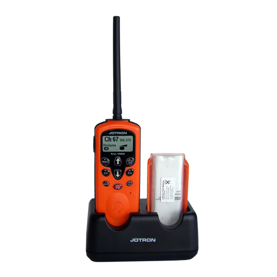
3.5.2 Charging the secondary battery The charger RCH-20 is a dual slot quick charger. The charger will accept a complete radio or the battery alone (see fig. 3.6.2). If two batteries are present, the charger will automatically start fast charging the second battery when the first battery is fully charged. -
Page 26: Battery Endurance
3.5.3 Battery endurance Battery type Standby time 5:5:90 (H) 10:10:80 (H) Tx:Rx:Standby Tx:Rx:Standby Lithium, 2900mAh NiMH, 1500mAh 2W at –20°C, ref. GMDSS spec., all other values are approximate values at 20°C. TR20 uses 1 and 2 W. 80078_UM_ TR20_ I... -
Page 27: Installation
INSTALLATION Connect the antenna before use and charge the battery fully before connecting to the equipment. Follow this manuals menu selection and set the battery option being used on the equipment to ensure the battery state indicator gives a true reading. -
Page 28: Operating Instructions
OPERATING INSTRUCTIONS 5.1 Configuring the TR20 The operation of TR20 is based on function keys and menus. The display indicates the chosen function by an arrow. To return to standard screen after operating the function keys, press “Enter”(11). To return to standard screen after entering the menus, press Menu”(3). 80078_UM_ TR20_ I... -
Page 29: Menu Flowchart
Menu Flowchart Ch 14 156.700 Setup Volume Contrast Single/DW/TW Menu Channels Backlight Key tone Key tone Info Info Battery Battery Contrast Ch 14 Contrast 156.700 Squelch Single/DW/TW Ch 14 156.700 Hi/Lo Single Volume Dual Watch Triple Watch Ch 16 Channels 156.800 Volume Triple Watch... -
Page 30: Standard Screen
5.2.1 Standard screen This is the standard/default screen for the TR20. The display returns to this mode after a break of more than 10 sec. In this mode the arrow buttons (2 & 9) adjusts the volume and the display gives a graphical volume indication. The selected channel is indicated with channel number and frequency. -
Page 31: Key Lock
5.2.2 Key Lock To prevent accidental operation of the keypad, the unit is equipped with a key lock. To enable the key lock, press «Menu» (3) and «Up» (2) simultaneously and hold for 1 sec. The same sequence will unlock the keys. - Page 32 Squelch - SQ To adjust the squelch level, press the button “SQ”(10). The level is adjusted by pressing the arrow buttons (2 & 9), and the display gives a graphical indication of the level. High and low output - Hi/Lo The «Hi/Lo»(5) button select between high and low output.
-
Page 33: Channel 16
5.4 Channel 16 By pressing the red “16”(6) key, the TR20 will enter channel 16. When on channel 16, PTT will function even if the key lock is enabled. Default display on TR20 during transmit. When the TR20 receive a signal the symbol “RX”... -
Page 34: Main Menu
5.5 Main menu When the “Menu”(3) key is pressed the operator has access to the main menu. The menu will scroll when pressing the arrow keys (2 & 9). When the arrow is pointing at the required parameter, press enter (11) to select. -
Page 35: Contrast
5.5.1 Contrast The contrast is adjusted by pressing the arrow buttons (2 & 9). The display gives a graphical indication of the level. 5.5.2 Single / DW / TW This feature enables TR20 to check for signals at one, two or three channels simultaneously. - Page 36 The radio will always keep on listening at channel 16 independent of the received channel.Setup of DW Press the Menu (3) Key and select Single/DW/TW Use the arrow keys (2 & 9) to move the cursor to DW, and press Enter (11). Press Menu (3) to return to the main display.
- Page 37 Setup of TW First we have to select the third watch channel. Press the Menu (3) Key and select Channels. Use the arrow keys (2 & 9) to move the cursor to the wanted channel and press “Enter” (11) for one second to select. TW will then be displayed next to the selected channel.
- Page 38 The working channel will then be displayed with large figures in the left part of the display, channel 16 and the third watch channel in the right part of the display. TW will then be indicated in the lower right corner of the display. The working channel can be changed at any time by pressing the “CH”...
-
Page 39: Key Tone
Note! The radio is not able to transmit when it is set to double or triple watch. To transmit, DW/TW has to be turned off by pressing the “Enter”(11) key. However, if channel 16 is selected it is always possible to transmit, regardless of the DW/TW setting. 5.5.3 Key tone Selectable On / Off tone for key- stroke operation. -
Page 40: Battery Selection
5.5.5 Battery selection To ensure correct battery status indication, the type of battery in use must be selected. 5.5.6 Select different channel sets Country Duplex Channels Simplex Channels International Canada See chapter 7 for complete listing of channels. Use the arrow keys (2 & 9) to move to the wanted channel set, and press ”ENTER”... -
Page 41: Maintenance And Troubleshooting
MAINTENANCE AND TROUBLESHOOTING 6.1 How to take care of your TR20 TR20 is constructed to endure the rough maritime environment. Still the life is dependent on taking care of the equipment. It is a good practice to regularly inspect and test the equipment to detect error symptoms and prevent more serious problems. -
Page 42: Regular Test Procedure
6.2 Regular test procedure It is important to perform regular testing to ensure proper operation in case of a distress situation. If TR20 is used regularly, perform test every month. When TR20 is stored in a lifeboat or raft, perform test at least once a year. -
Page 43: Cleaning Of Dirt And Oil
IMPORTANT! The TR20 is a sealed waterproof radio and there are no user serviceable parts inside. It must never be opened, except by authorised Jotron AS agents. Unauthorised disassembly will invalidate the warranty. See the next chapter for failure diagnosis. This may be of help when discussing problems with a Jotron AS agent. -
Page 44: Guide To Troubleshooting
6.5 Guide to troubleshooting Troubleshooting steps: Problem Possible causes Possible solutions No indication on Battery is discharged. Charge or change battery package. display You know there is a a) Squelch is muting. a) Adjust squelch to 0. signal coming, but b) Failure in receiver. - Page 45 Problem Possible causes Possible solutions a) Try a reset by switching power E1 is indicated on the Frequency synthesizer is OFF. display. out of lock. b) Failure in frequency synthesizer. An authorised agent must service the unit. E2 is indicated on the Failure in transmitter An authorised agent must service the display.
-
Page 46: Maritime Vhf Channels
MARITIME VHF CHANNELS Channel CAN RX Designators Int. RX USA RX GMDSS channels 156.000 156.000 156.000 160.625 156.025 (*1) 160.625 156.025 160.650 156.050 160.650 156.050 160.675 156.075 160.675 156.075 160.700 156.100 (*1) 160.700 156.100 160.725 156.125 (*1) 160.725 156.125 160.750 156.150 160.750 156.150... - Page 47 Channel CAN RX Designators Int. RX USA RX GMDSS channels 156.650 156.650 156.650 156.650 156.675 156.675 156.675 156.675 156.700 156.700 156.700 156.700 156.725 156.725 156.725 156.725 156.750 156.750 156.750 156.750 156.775 156.775 156.800 156.800 156.800 156.800 156.825 156.825 156.850 156.850 156.850 156.875 156.875...
- Page 48 157.425 157.425 157.425 WX01 162.550 WX02 162.400 WX03 162.475 WX04 162.425 WX05 162.450 WX06 162.500 WX07 162.525 (*) These channels are prohibited to transmit on in the USA. The Jotron agent can insert additionally 20 national channels. 80078_UM_ TR20_ I...
- Page 49 PRACTICAL USE, VHF TRANSMISSION RANGE The range of VHF communications is limited to „line of sight‟, because the VHF radio waves are travelling in straight lines. A higher position of the transceiver will then increase the coverage. This applies both to the receiving and transmitting end.
- Page 50 SPARE PARTS AND ACCESSORIES Description 99930 Tron TR-20 GMDSS, transceiver only 80060 Lithium battery, not rechargeable. 80059 NiMH 7.2V, 1500mAh rechargeable battery pack 99920 Dual slot fast charger for 80059 batteries. 80080 Mains adapter for 99920 EURO style ...
- Page 51 10 SERVICE AGENTS Please look at www.jotron.com for Marine Service Agents. Jotron Group subsidiary companies: Jotron (UK) Ltd. Jotron USA, Inc. Crosland Park, Off Crowhall Road 10645 Richmond Avenue, Cramlington Suite 140 Northumberland NE23 1LA Houston, TX 77042 United Kingdom...
- Page 52 80078_UM_ TR20_ I...
Need help?
Do you have a question about the TRON TR20 GMDSS and is the answer not in the manual?
Questions and answers