Table of Contents
Advertisement
Quick Links
Advertisement
Table of Contents

Related Manuals for THORLABS CM401


Summary of Contents for THORLABS CM401
- Page 1 CM401 Hyperspectral Imaging System User Guide...
- Page 2 Copyright © February 11, 2022 Thorlabs, Inc. All rights reserved. Information in this document is subject to change without notice. The software described in this document is furnished under a license agreement or nondisclosure agreement. The software may be used or copied only in accordance with the terms of those agreements.
-
Page 3: Table Of Contents
3.2. Specifications Overview ....................4 Getting Started ........................5 Chapter 4 4.1. Unpacking and Inspection ................... 5 4.2. Setting up the CM401 ....................6 4.2.1. General Setup ........................6 4.2.2. System Installation ........................ 6 Capturing an Image ......................9 Chapter 5 Maintaining the CM401 .................... -
Page 4: Chapter 1 Warning Symbol Definitions
CM401 Hyperspectral Imaging System Chapter 1: Warning Symbol Definitions Warning Symbol Definitions Chapter 1 Below is a list of warning symbols you may encounter in this manual or on your device. Symbol Description Direct Current Alternating Current Both Direct and Alternating Current... -
Page 5: Chapter 2 Safety
Any modification or servicing of this system by unqualified personnel renders Thorlabs free of any liability. Only personnel authorized by Thorlabs and trained in the maintenance of this equipment should remove any covers or housing or attempt any repairs or adjustments. -
Page 6: Chapter 3 Description
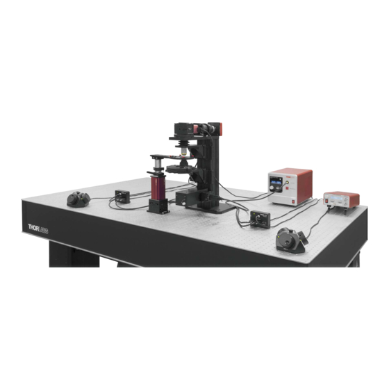
Chapter 3: Description Description Chapter 3 Thorlabs’ Hyperspectral Imaging System provides a platform to study a sample with co-located features. In hyperspectral imaging, a stack of spectrally separated, two-dimensional images is acquired. This allows quick sample identification and analysis. The Hyperspectral Imaging System consists of Thorlabs’ flexible Cerna ®... -
Page 7: Specifications Overview
CM401 Hyperspectral Imaging System Chapter 3: Description 3.2. Specifications Overview The following table provides an overview of the CM401 specifications. For detailed specifications on individual devices, see the Specifications Chapter on page 15. Specification Value Microscope Cerna Series Modular Microscope... -
Page 8: Chapter 4 Getting Started
This section is provided for those interested in getting the Hyperspectral Imaging System up and running quickly. 4.1. Unpacking and Inspection Open the package and carefully remove the CM401 and its accessories. The table below lists the standard accessories shipped with the device. Name... -
Page 9: Setting Up The Cm401
• Acquire images using actively isolated or anti-vibrational table platforms. Failure to utilize appropriate platforms results in poor quality images. Thorlabs offers a wide array of optical tables and platforms that provide the necessary stability for your imaging needs. •... - Page 10 CM401 Hyperspectral Imaging System Chapter 4: Getting Started 3. Mount the objective, camera, and condenser onto the microscope body. Figure 4-2 Mounting the Accessories 4. Mount the rigid stand onto the optical table. 5. Mount the MCM3001 Controller Boxes (2X) onto the optical table.
- Page 11 CM401 Hyperspectral Imaging System Chapter 4: Getting Started C. Cable Connections 1. Connect the MCM3001 controllers to the Controller Boxes, as shown in the figure. 2. Connect the cables form the rigid stand (X and Y axes) and the motorized objective arm to one of the MCM3001 Controller Boxes.
-
Page 12: Chapter 5 Capturing An Image
OK. Figure 5-1 Standard Device Requirement for CM401 3. Use the Z Control panel to focus on the sample. 4. In the Capture Setup tab, make sure that the Camera Control panel, Kurios Filter panel, and Z Control panel are visible. - Page 13 CM401 Hyperspectral Imaging System Chapter 5: Capturing an Image 5. In the Kurios Filter panel, set the value for Start, Stop, and Step Size. You can set the Start and Stop values between 420-730 nm. Figure 5-2 displays a Start value that is set to the minimum wavelength (420 nm) of the KURIOS filter.
- Page 14 CM401 Hyperspectral Imaging System Chapter 5: Capturing an Image Figure 5-3 Camera Control Panel 8. Enter the Stop value as the Wavelength (for example, 730 nm). 9. In the Camera Control panel, change the Exposure value until you see the desired brightness on the image.
- Page 15 CM401 Hyperspectral Imaging System Chapter 5: Capturing an Image Figure 5-5 Hyperspectral Sequence 11. Choose an arbitrary value between the Start and Stop wavelengths. In the Kurios Filter panel, enter the arbitrary value for the Wavelength. 12. In the Camera Control panel, change the Exposure value until you see the desired brightness on the image.
- Page 16 CM401 Hyperspectral Imaging System Chapter 5: Capturing an Image 15. In the Capture tab, select Hyperspectral for Capture Mode. This option is only visible if you select Scientific Camera as the Image Detector and ThorKurios as the Spectrum Filter in the Hardware Connection window.
-
Page 17: Chapter 6 Maintaining The Cm401
Maintaining the CM401 Chapter 6 This unit does not need regular maintenance. If you suspect a problem with your CM401, please contact our nearest office for assistance from an application engineer (see the Thorlabs Worldwide Contacts Chapter on page 24 for details). -
Page 18: Chapter 7 Specifications
CM401 Hyperspectral Imaging System Chapter 7: Specifications Specifications Chapter 7 7.1. Microscope Body Specifications Specification Value Rail Length 95 mm Throat Depth 196.5 mm (7.74") External M32 x 0.75 Threads Objective Thread Adapter (Included) Internal M25 x 0.75 Threads 7.2. -
Page 19: Objective Specifications
CM401 Hyperspectral Imaging System Chapter 7: Specifications 7.4. Objective Specifications Specification Value Item # N10X-PF Magnification Manufacturer Part # MRH00101 Numerical Aperture (NA) Working Distance (WD) 16 mm Parfocal Length 60 mm Compatible Tube Lens Focal Length 200 mm Coverslip Correction 0.17 mm... -
Page 20: Tunable Bandpass Filter Specifications
CM401 Hyperspectral Imaging System Chapter 7: Specifications 7.6. Tunable Bandpass Filter Specifications Specification Value Item # KURIOS-VB1 420 – 730 nm Wavelength Narrow: 10 nm FWHM Bandwidth, CWL = 550 nm Medium: 18 nm FWHM Wide: 32 nm FWHM Narrow: <230 ms Switching Speed Medium: <150 ms... -
Page 21: Camera Specifications
CM401 Hyperspectral Imaging System Chapter 7: Specifications 7.8. Camera Specifications Specification Value Monochrome Item # CS126MU Sensor Type CMOS Monochrome Effective Number of Pixels (Horizontal x Vertical) 4096 (H) x 3000 (V) (~12. 3 MP) Pixel Size 3.45 µm x 3.45 µm Optical Format 1.1"... -
Page 22: Motorized Controller Specifications
CM401 Hyperspectral Imaging System Chapter 7: Specifications 7.9. Motorized Controller Specifications Specification Value Item # MCM3001 Motor Output Motor Drive Voltage 24 V 7.0 A (Peak) Motor Drive Current 3.0 A (RMS) Motor Drive Type 12-Bit PWM Control Control Algorithm... -
Page 23: 7.10. Plasma Light Source Specifications
CM401 Hyperspectral Imaging System Chapter 7: Specifications 7.10. Plasma Light Source Specifications Specification Value Item # HPLS343 Physical 14.23" x 7.40" x 7.87" Dimensions (L x W x H) (361.5 mm x 188.0 mm x 200.0 mm) 10 to 30 °C (Open and Closed Loop) Operating Temperature 10 to 35 °C (Eco Mode) -
Page 24: Chapter 8 Mechanical Drawing
CM401 Hyperspectral Imaging System Chapter 8: Mechanical Drawing Mechanical Drawing Chapter 8 8.1. Microscope without Sample Holder Rev C, July 15, 2022 Page 21... -
Page 25: Microscope With Sample Holder
CM401 Hyperspectral Imaging System Chapter 8: Mechanical Drawing 8.2. Microscope with Sample Holder Page 22 TTN131444-D02... -
Page 26: Chapter 9 Regulatory
Waste Treatment is Your Own Responsibility If you do not return an “end of life” unit to Thorlabs, you must hand it to a company specialized in waste recovery. Do not dispose of the unit in a litter bin or at a public waste disposal site. -
Page 27: Chapter 10 Thorlabs Worldwide Contacts
CM401 Hyperspectral Imaging System Chapter 10: Thorlabs Worldwide Contacts Chapter 10 Thorlabs Worldwide Contacts For technical support or sales inquiries, please visit us at www.thorlabs.com/contact for our most up-to-date contact information. USA, Canada, and South America UK and Ireland Thorlabs, Inc. - Page 28 www.thorlabs.com...
Need help?
Do you have a question about the CM401 and is the answer not in the manual?
Questions and answers