Table of Contents
Advertisement
Quick Links
Advertisement
Table of Contents

Related Manuals for THORLABS CS2010


Summary of Contents for THORLABS CS2010
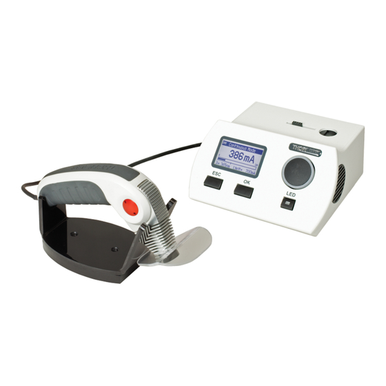
- Page 1 LED UV Curing System CS2010 Operation Manual 2018...
- Page 2 Version: Date: 09-Jul-2018 Item No.: M0009-510-523 Copyright © 2018 Thorlabs...
-
Page 3: Table Of Contents
4.1 Software Installation 4.1.1 Install NI-VISA 4.1.2 Install Application Software 4.1.3 Install Device Drivers 5 Connect CS2010 6 Graphic User Interface (GUI) 6.1 Menu Bar 6.2 Continuous Mode 6.3 Timer Mode 6.4 Configuration Mode 6.5 Slope Mode 7 Maintenance and Service 7.1 Version Information... - Page 4 8.1 Technical Data 8.2 Certifications and Compliances 8.3 Warranty 8.4 Copyright and Exclusion of Reliability 8.5 Thorlabs 'End of Life' Policy 8.6 List of Acronyms 8.7 Thorlabs Worldwide Contacts...
-
Page 5: Foreword
Paragraphs preceeded by this symbol explain hazards that could damage the instrument and the connected equipment or may cause loss of data. Note This manual also contains "NOTES" and "HINTS" written in this form. Please read these advices carefully! © 2018 Thorlabs... -
Page 6: General Information
CS2010 1 General Information The Thorlabs LED spot UV curing system is designed for curing (hardening) of certain inks, coatings, and adhesives which are formulated with photoinitiators and resins. When exposed to the correct energy and irradiance in the required band of UV light, polymerization occurs, and so the adhesives harden or cure. -
Page 7: Requirements
1 General Information 1.3 Requirements These are the requirements to the PC intended to be used for remote operation of the CS2010. 1.3.1 Hardware Requirements CPU: 1 GHz or higher RAM: 1 GB Graphic card with at least 32 MB memory Hard disc with at least 100 MB free storage space Free USB2.0 port... -
Page 8: Installation
Inspect the shipping container for damage. If the shipping container seems to be damaged, keep it until you have inspected the contents and you have inspected the CS2010 mechanically and electrically. Verify that you have received the following items within the package: CS2010 driver Wide range power supply (24V DC 1.5A) and power cord... -
Page 9: Operating Elements
Handset with slewing LED head 10 Collimated UV LED output - Warning 11 UV protection shield 12 LED ON/OFF switch on handset 13 Hand set holder Warning Do NOT look into the output! Do NOT direct the UV emission onto skin! © 2018 Thorlabs... -
Page 10: Rear Panel
CS2010 2.4 Rear Panel Power switch LED output (connector for hand set) 3.5mm jacket for foot switch USB 2.0 connector (remote computer) DC input Serial number © 2018 Thorlabs... -
Page 11: Operating Instruction
In Continuous Mode, this changes the function of the LED ON/OFF switches (5) and (12) between "Toggle" (push to switch on, push again to switch off) and "Hold" (the LED emits UV light only as long as the button is pushed). © 2018 Thorlabs... -
Page 12: Continuous Mode
- Press OK to enter edit mode: - Use the rotary knob to select a number, a character, the underscore or the backspace (delete) button. When the desired set name is completed, select "Done" to confirm and return to the previous menu: © 2018 Thorlabs... -
Page 13: Slope Mode
In this mode, the LED intensity can changed during exposure. Entering this mode, exposure time, start intensity and end intensity can be set. Pushing LED button executes the ramp and the timer counter appears, emitting a beep according to the set interval. © 2018 Thorlabs... -
Page 14: Irradiance Mode
This applies to all stored exposure time values in Timer Mode, Slope Mode and pre-configurations: Note The measured value corresponds to the irradiance in an 8mm distance from the LED without optics (equal to 5mm from the front of the handset). © 2018 Thorlabs... -
Page 15: User Limit
Any lower limit can be set. Note: If the intensity value is set to %, 100% always refers to the LED current limit as set. 3.8 About This menu item displays information on the hardware and firmware: © 2018 Thorlabs... -
Page 16: Computer Interface
CS2010 4 Computer Interface The CS2010 curing system can be remotely controlled by a PC via USB interface. The control software is included with the attached CD. After installation of the software, the CS2010 can be connected to the computer using the attached USB cable. - Page 17 4 Computer Interface Please click "Next" in following screens to continue: In the following 2 steps, please select "I accept the License Agreement" if you do so and click Next: © 2018 Thorlabs...
- Page 18 CS2010 The installer will sum up the components to be installed. Click Next to continue installation: After installation of NI-VISA™ Software, click Finish. Please restart your computer to complete the installation of National Instruments Software © 2018 Thorlabs...
-
Page 19: Install Application Software
4 Computer Interface 4.1.2 Install Application Software Click to "CS2010 - Application Software" Click "Next" to continue. Accept the proposed installation folder, or browse for an alternative location. "Disk Cost" will calculate the required free disk space. © 2018 Thorlabs... - Page 20 CS2010 Then click "Next" to continue. Check the "I Agree" button, if you do so, and click "Next" to continue. Click "Next" to continue. © 2018 Thorlabs...
- Page 21 Click "Next" to continue. Windows Security may alert you about potential risks: Please click to the "Install" button to complete the device driver installation. Click "Finish" to proceed. Click "Next" and in the following screen to "Close" to complete the installation process. © 2018 Thorlabs...
-
Page 22: Install Device Drivers
CS2010 4.1.3 Install Device Drivers Thorlabs provides beside the application software a driver package, which can be used by C/C+ +/LabVIEW and every programming language supporting DLLs. To install the driver package, click "Install Instrument Drivers" In the next two screens click "Next" to continue: In the following 2 steps, please select "I accept the License Agreement"... - Page 23 To complete instrument driver installation, click "Finish". Note · Please be aware that you need a VISA engine installed on your system to use the CS2010 - VISA Instrument Driver. · Please refer to the manuals, which are copied on your system when installing the device driver.
-
Page 24: Connect Cs2010
· Connect the handset to the CS2010 driver · Connect power supply to AC power and to CS2010 · Switch on the UV curing system · Connect the driver to the control PC using the USB2.0 cable. -
Page 25: Graphic User Interface (Gui)
Select the instrument, then "Accept". The GUI (Graphic User Interface) activates. The display (1) of the CS2010 will show the same menu as selected in the software. The software reads out settings of the hardware and displays them. The following parameters and settings cannot be changed remotely: ·... -
Page 26: Menu Bar
CS2010 6.1 Menu Bar Select "Menu" to connect or disconnect the CS2010 and to exit the program: Select Configuration to set user current limit: Note The numeric value for Limit (to the right) is the hardware limit, read out from the EEPROM in the handset and cannot be changed. -
Page 27: Continuous Mode
Continuous Mode Set the desired Output intensity by either moving the slider or by entering a numeric value and control the LED by clicking to Handset Output button. Intensity change is possible with LED ON or OFF. © 2018 Thorlabs... -
Page 28: Timer Mode
The software Timer Mode is equivalent to hardware Timer Mode In the Timer Mode tab, the desired LED intensity and exposure time can be selected. Clicking to the Handset Output button starts / aborts the timer count down. © 2018 Thorlabs... -
Page 29: Configuration Mode
Set to save settings: To operate the CS2010 with a configuration, just select it and click the Handset Output button to start/abort exposure. © 2018 Thorlabs... -
Page 30: Slope Mode
CS2010 6.5 Slope Mode The tab Slope Mode in CS2010 software is equivalent to the topic Slope Mode of the driver. Select the values for start and end intensity of the slope and the exposure time. The button Handset Output starts and terminates the exposure. -
Page 31: Maintenance And Service
ð The LED or the handset are defective. Please contact Thorlabs for return instructions. · Over temperature protection ð The CS2010 driver overheated during operation. Make sure that ventilation gaps (8) in the cabinet are not blocked. © 2018 Thorlabs... -
Page 32: Appendix
95 mm x 180 mm x 32 mm Warm Up Time for Rated Accuracy <10 min Weight <1 kg ) not included in base package ) non-condensing All technical data are valid at 23 ± 5°C and 45 ± 15% rel. humidity (non condensing) © 2018 Thorlabs... -
Page 33: Certifications And Compliances
Replaces 89/336/EEC Compliance demonstrated using high-quality shielded interface cables. Emissions, which exceed the levels required by these standards, may occur when this equipment is connected to a test object. Minimum Immunity Test requirement. Replaces 73/23/EEC, amended by 93/68/EEC. © 2018 Thorlabs... -
Page 34: Warranty
For warranty repairs or service the unit must be sent back to Thorlabs. The customer will carry the shipping costs to Thorlabs, in case of warranty repairs Thorlabs will carry the shipping costs back to the customer. -
Page 35: Copyright And Exclusion Of Reliability
Thorlabs dealer or system installer. All rights reserved. This document may not be reproduced, transmitted or translated to another language, either as a whole or in parts, without the prior written permission of Thorlabs. Copyright © Thorlabs 2018. All rights reserved. -
Page 36: Thorlabs 'End Of Life' Policy
Waste treatment on your own responsibility If you do not return an “end of life” unit to Thorlabs, you must hand it to a company specialized in waste recovery. Do not dispose of the unit in a litter bin or at a public waste disposal site. -
Page 37: List Of Acronyms
International Electrotechical Commission Light Emitting Diode Liquid Crystal Personal Computer RoHS Restriction of the use of certain hazardous substances in electrical and electronic equipment Software Universal Serial Bus Ultra Violet WEEE Waste Electrical and Electronic Equipment Directive © 2018 Thorlabs... -
Page 38: Thorlabs Worldwide Contacts
Email: europe@thorlabs.com Email: scandinavia@thorlabs.com France Brazil Thorlabs SAS Thorlabs Vendas de Fotônicos Ltda. 109, rue des Côtes Rua Riachuelo, 171 78600 Maisons-Laffitte São Carlos, SP 13560-110 France Brazil Tel: +33-970 444 844 Tel: +55-16-3413 7062 Fax: +33-825 744 800 Fax: +55-16-3413 7064 www.thorlabs.com...
Need help?
Do you have a question about the CS2010 and is the answer not in the manual?
Questions and answers