
Related Manuals for Bishamon X Series


Summary of Contents for Bishamon X Series
- Page 1 Operation and Service Manual Lifter X Series Model NX・X1ton・2X X2ton・X3ton Series Sugiyasu Corporation Aug. 2007...
-
Page 2: Table Of Contents
Preface Before operating, an operator should read this manual carefully and understand completely. Keep this manual for further reference. In case of lost of this manual, please ask your local supplier for a new copy. Also in case of lost or any damage of WARNING/CAUTION decal, please ask your local supplier for a replacement. Note: On this manual WARNING means the danger, which could lead death or serious injury. CAUTION means the danger, which could lead slight injury or property damage. W a r n i n g In this manual, 「 Danger」 , 「 Warning」 , 「 Caution」 are defined and specified as below. Notice of Warnings are very important for safe operations. As these are very important to protect operators from accident resulting in injury or death, or damage to properties, make certain to understand them fully before operating lift. Danger ・ ・ ・ ・ ・ Incorrect may imminently result in operation serious injury or death of the operator. -
Page 3: Warnings And Cautions
Warnings and Cautions Warning Follow the instruction otherwise death or serious injury may occur. DO NOT lift people. People could fall and could create severe injury. DO NOT enter under the table. In case you have to, unload the lifter and lock the safety bar. DO NOT put a foot or a hand in scissors mechanism. DO NOT put a foot under the table. DO NOT overload the lifter. It may lead load fall or damage on the lifter. When transferring load to the table, occasionally unbalanced load might lead the lifter fall. In used for transfer purpose, ask the manufacturer for information in advance. ー 1 ー... - Page 4 Caution 1. Read this operation manual carefully and understand completely before operating the lifter. Improper operation leads to an accident. 2. This lifter is designed to lift up and down the load under the rated capacity, using more than 80% of the table surface. Do not use the lifter for other purpose than its intended use. 3. The tact time of this lifter should be more than three minutes. Do not use it at high frequency or high speed. 4. Do not allow person to operate the lifter, who does not understand its operation. 5. Keep watching the load condition. Stop operation of the lifter if the load becomes unstable. 6. Practice maintenance work according to the service manual. 7. Do not modify the lifter without the manufacture s written consent. 8. Put the load well-balanced on more than 80% of the table surface while lifting the load. Unbalanced load leads to machine damage or poor durability. 9. Be aware of unbalanced load while transferring the load. 10. Remove load from the table and lock the safety bar at the time of maintenance and inspection. 11. Stop operating immediately when the table reaches to the highest or lowest possible position. The motor or the coil would overheat and burn out. 12. Do not put unbalanced load on the table as shown below. ー 2 ー...
-
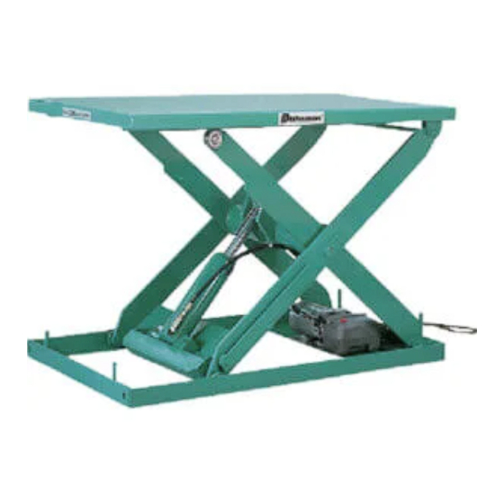
Page 5: Name Of Parts
Name of parts Table Table Link Hydraulic unit Link High pressure hose Cylinder Cylinder Hydraulic unit Base High pressure hose Safety bar for maintenance Safety bar for maintenance Base NX100WC X10410 Installation of lifter Warning Follow the instruction otherwise death or serious injury may occur. Do not install the lifter on inclined surface. It leads to damage or fall of the lifter. Do not hold the table when moving the lifter. One side of the table may be lifted and it leads to a danger. Hold the base when moving the lifter. Caution 1. Installation should be done where there is no space between the base and the floor. In case of any space, the base may bend. 2. The power cable should be shorter than 10M and its cross section should be larger than 2 square millimeter. Long or thin cable may cause overheat of the motor or the cable, which leads to a danger. 3. Install the lifter where the ambient temperature is between 0℃ to 30℃. 4. This lifter is not designed to be water-proof or for outdoor use. Install the lifter indoor under dry circumstances. ー 3 ー... -
Page 6: Daily Inspection Before Working
1. Check if the installation floor is flat. Caution ※ Install the lifter where the ambient temperature is between 0℃ to 30℃. ※ This lifter is not designed to be water-proof or for outdoor use. Install the lifter indoor under dry circumstances. 2. Unpack the lifter and place it at the desired place. In case of any space between the base and the floor, fill it with some spacer or cement. Caution ※ Do not hold the table while moving the lifter. One side of the table may be lifted, which leads to a danger. 3. Connect the power cable to the power source and check the movement of the lifting unit. Caution ※ If the table does not rise while the motor is working, this could be due to the opposite rotation or single phase movement of the motor. In that case, exchange two of three cables or make sure if all three cables are connected and turned on. ※ The power cable should be shorter than 10M and its cross section should be larger than 2 square millimeter. Long or thin cable may cause overheat of the motor or the cable, which leads to a danger. 4. If necessary, fix the lifter with anchor bolts. Daily inspection before working Daily inspection is important for safety and early discovery of malfunction. Check the followings before working. (1) Check if there is any abnormality on the appearance. (2) Check if there is any foreign article inside of the lifting unit. (3) Check if the quantity of oil is sufficient. (4) Check oil leakage from the piping, cylinder or hydraulic unit. (5) Check if there is any abnormality on the electric circuit. Check if the lifting movement is smooth. (6) Check unusual wear on the lifting unit. (7) Check unusual noise from the lifting unit, motor or pump. (8) Check the looseness of the screws and bolts. Caution Remove the load from the table and lock the safety bar while working under the table for maintenance or inspection. ー 4 ー... -
Page 7: Operation Of Lifter
Operation of lifter This lifter is operated by push buttons or foot switch. Push UP button (pedal) and the table goes up. Push DOWN button (pedal) and the table goes down. Caution Stop operating immediately when the table reaches to the highest or lowest possible position. The motor or the coil would overheat and burn out. UP DOWN pedal pedal Safety bar UP button This lifter is equipped with a safety bar in case of working under the DOWN button table for maintenance or inspection. Lock the safety bar without fail while working under the table for maintenance or other works. Push button switch Foot switch How to lock a safety bar (1) Remove all loads from the table. Link (2) Raise the table at the highest position. Safety bar (3) Rotate the safety bar and put it on the base. (4) When lowering the table, the safety bar touches the base end, which stops the table (5) That is how to lock the safety bar. Practice maintenance. (6) After maintenance, raise the table and put the Safety bar put on the base safety bar back to the link. Periodical inspection Warning Remove the load from the table and lock the safety bar while working under ... -
Page 8: Adjustment Of Lowering Speed
Lubrication A: Put grease in grease nipple B; Apply grease C: Lubricate Oil used for Lifter There is a gauge in the oil plug. Classification of viscosity Make sure if the oil surface is between : ISO VG32 anti-wearing hydraulic oil. the indicated lines. Name Brand Oil tank Nuto H32, HP32 Esso Uni-power SQ32, SL32 Showa Shell Terrace oil 32, K32 Mobile DTE24 Mobile Indicated line Adjustment of lowering speed Warning ※ The lowering speed is preset under the specified load before delivery. Adjust the speed as less as possible because too much increase of lowering speed may leads to a danger. ※ When speed is adjusted with no load, there might be a case that lowering speed gets too fast with load, which leads to a danger. 1. NX, X1ton, 2X Series 1) Loosen the nut with 17mm spanner. L hex. wrench 2) Turn the adjusting screw (hex. hole (5mm) headed) with 5mm hexagon wrench and adjust the speed. Adjusting screw Clockwise………………………… Slow ( hex. hole headed ) ... -
Page 9: Hydraulic Circuit And Electric Circuit
2X10918, 2X11218 Coil 1> Loosen the nut with 13mm spanner. 2> Turn the adjusting screw (hex. hole Lock nut headed) with 4mm L hexagon wrench. (spanner 13mm) Clockwise ………………… Fast Counterclockwise……… Slow 3> To fix the nut, hold the adjusting screw L hexagon wrench (4mm) with L hexagon wrench and tighten the Adjusting screw (hex. hole headed) nut. 2. X2ton, X3ton Series 1) Loosen the lock nut 1 with 13mm spanner. 2) Remove the stopper. 3) Loosen the lock nut 2 with 13mm Stopper spanner. 4) Adjust the speed with 4mm hexagon Slow Fast wrench. Clockwise ………………… Fast Adjusting valve Counterclockwise……… Slow Lock nut 2 4mm 5) Tighten the lock nut 2. -
Page 10: Trouble Shooting
Trouble shooting Trouble Cause Countermeasure Malfunction Electricity Reverse rotation of the motor Exchange two of three cables of table Single phase operation Verify three phase operation lifting Malfunction of the magnet Coil burnout switch Poor contacting of the switch or cable disconnecting Thermal relay is working. Poor contacting of the magnet Check the switch contact and replace it switch with a new one (with case) if necessary. Always open valve owing to a Remove the foreign object or replace Valve foreign object in the lifting the lifting valve valve Set the pressure as designated by Improper pressure adjustment adjusting the relief valve. with the relief valve (Do as less as possible in principle) Supply hydraulic oil. (When the table is Oil shortage Hydraulic at the highest position, oil should be 10mm up from the filter surface.) Malfunction at the rated relief Replace the pump. Pump valve pressure Under specified capacity owing ... -
Page 11: Disposal
Disposal For proper disposal, divide the lifter into 4 categories; ferrous material, nonferrous material, resin material and hydraulic oil and dispose them as industrial waste. If you have any questions, contact your supplier before disposal. Warranty We warrant the products manufactured by Sugiyasu Corporation to be free from defects in workmanship and material for 1 year. Our obligation under this warranty is limited to repair or replacement, at our option, of any parts or material which, within this warranty period, are found to our satisfaction to be defective. The belows are not covered by the warranty. 1 The damage or trouble caused by the false operation, negligence of the maintenance and storage required. 2 The damage or trouble caused by the modification that affects the originally designed functions. 3 Any consumable parts that need to be replaced. 4 The damage or trouble caused by natural disaster such as fire, earthquake, flood etc. 5 The damage or trouble caused by not using the original manufacturer s parts. 6 The required information such as serial No. etc.would not be provided. 7 The damage or trouble caused by improper installation. ※ Any consumable parts such as rubber parts etc. are not covered under this warranty. ※ As this lift is not weatherproof, trouble caused by corrosion, rust, short circuit from water are not covered under this warranty. How to claim For warranty claim under the above said provision, contact your supplier and the supplier will take the required procedure. However please note to accept the claim or not, is totally judged by the manufacture. ー 9 ー... -
Page 12: After Service
・ Repair under warranty period ⇒ Will be repaired in accordance with warranty rules ・ Repair after warranty period ⇒ Contact your supplier ・ Availability of Spare Parts ⇒ The spare parts is available for 8years after discontinuing manufacturing Contact your supplier for any information regarding to the after service. When contacting your supplier, provide Model No., Serial No., purchase date and conditions of trouble. For your records and future contact, fill out below. Model No. Serial No.. Purchase Date Supplier Name Address Tel. No. Installer Name Address Tel. No. Trouble Date and Date : Date : conditions Date : Date : Date : SUGIYASU CORPORATION 3-21,4-CHOME,HONGO-CHO,TAKAHAMA CITY,AICHI,JAPAN 444-1394 TEL(0566)53-1126 FAX(0566)53-1844 http://www.bishamon.co.jp/ ー 10 ー EOM-X-0708-100KU...
Need help?
Do you have a question about the X Series and is the answer not in the manual?
Questions and answers