Table of Contents
Advertisement
Quick Links
July 2019
FANTAS Lift
BSC3200 Series
Operation and
Service Manual
To Users
Thank you very much for purchasing a FANTAS Lift BSC3200 series lift of Bishamon. Be sure to read
this Operation Manual before using the lift and start using only after understanding its contents.
Furthermore, keep this operation manual with care and promptly request for a copy if it becomes lost.
If the operation manual is not for the actual lift, request for a correct copy with the retailer from whom
the product was purchased.
Notes on Maintenance, Inspection and Control
Perform maintenance and inspection of the lift. Perform periodical maintenance and inspection of the
lift, in order to ensure safe operation of the lift and sufficient function of the lift is maintained.
Advertisement
Table of Contents

Subscribe to Our Youtube Channel
Related Manuals for Bishamon BSC3200 Series


Summary of Contents for Bishamon BSC3200 Series
- Page 1 Service Manual To Users Thank you very much for purchasing a FANTAS Lift BSC3200 series lift of Bishamon. Be sure to read this Operation Manual before using the lift and start using only after understanding its contents. Furthermore, keep this operation manual with care and promptly request for a copy if it becomes lost.
- Page 2 Preface Before operating the lift, READ and be familiar with this operation manual. Incorrect operation by not READing and not being familiar with the operation manual may result in not only poor performing of the lift functions but also the falling of the vehicles and accident of injury or death.
-
Page 3: Table Of Contents
Table of Contents Table of Contents....................2 1. Objects of the Lift ..................... 3 2. Danger, Warning and Caution ................3 3. Types and Attachment Locations of Warning Labels ........8 4. Components of the Lift ..................9 5. Safety Devices ....................12 6. -
Page 4: Objects Of The Lift
1. Objects of the Lift This lift is designed for indoor use, intended for changing oil and parts, general maintenance work as well as inspection and servicing of light to ordinary passenger vehicles, recreational vehicles, compact trucks (excluding long-body vehicles) and excludes washing of vehicles. 2. - Page 5 Warning Read the Operation Manual thoroughly before using the lift. Important warnings are described. Failing to follow warnings leads to serious accidents. Set the center of gravity of the vehicle to within the range specified with yellow color on the lift. The vehicle may potentially fall while the lift is raised or lowered, or due to vibration arising from performing work, as well as from detaching and attaching parts.
- Page 6 Warning Electrical Hazard DO NOT open control box or remove cover plates without isolating electrical supply. It may result in electric shock. DO NOT lower the lift while any stand or support is in position under vehicle. DO NOT use “Down” motion of the lift for any other purpose except lowering (ex.
- Page 7 Caution <Preparation> This lift is designed for maintenance and servicing of vehicles. Do not use the lift for purposes other than those for which it is intended. Stop using the lift if even a single safety device fails to operate properly. Wet tires and supporters require attention, as they can cause slippage.
- Page 8 Caution <Generally> Always bring the lift to the lowest position when moving away from the lift or when not using the lift. Start lift operations only after verifying that Lowering Stop Hook are “Engaged”. Do not allow anyone other than trained mechanic to approach the lift. Do not leave the lift with a vehicle raised unattended for long periods of time.
-
Page 9: Types And Attachment Locations Of Warning Labels
3. Locations of Warning Labels BSC3200KUV ① “Center of Gravity Position” label ② Capacity label ③ Caution label BSC3200KV ④ “Danger” and “Warning” labels Caution Labels feature descriptions on important matters for preventing personal accidents and property damages, as well as capacity of the lift. Purchase and apply these labels promptly when they become worn, damaged or peeled off while the lift is used. -
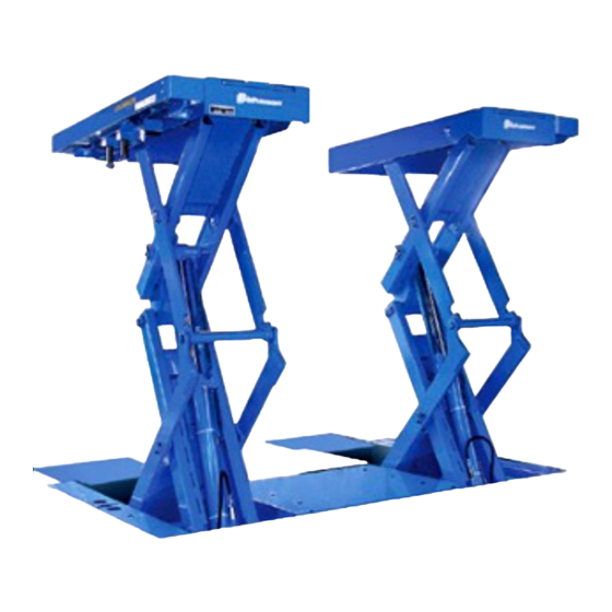
Page 10: Components Of The Lift
4. Components of the Lift Sliding supporter Swing arm Control box Arm support Filter regulator Push button control switch Lowering stop device Arm pit cover Sliding cover BSC3200KUV Built-in hydraulic unit Cylinder Sliding supporter Swing arm Arm pit cover Arm support Separately installed hydraulic unit Push button control switch... - Page 11 Push button control switch This is switch for raising and lowering the lift and arms. ● Switch for raising and lowering lift Press Up button to raise the lift and release it to stop the lift at that position. Press Down button to lower the lift and release it to stop the lift at that position.
- Page 12 Swing arm Swing arms can be freely rotated, extended and retracted within the range of about 90 degrees to align rubber mounts to jack points. Swing arm is more suitable to lift up one box car and SUV (RV) which can not be lifted up by plate type supporter.
-
Page 13: Safety Devices
5. Safety Devices They are installed at each cylinder to prevent lift from falling in case of oil leaking and breakage of hydraulic hoses Lowering stop etc. hook However, please note that there is no lowering stop hook below approx. 500 mm from bottom. -
Page 14: Pre-Operation Checks
6. Pre-Operation Checks 6-1. Items for Pre-Operation Checks This is a very important for preventing fall accident involving a vehicle and personal injury, by making routine work that involve the use of the lift safe. Perform the pre-operation checks before operation every day. -
Page 15: Inspecting Filter Regulator
6-2. Inspecting Filter Regulator The regulator features the function to reduce pressure of air supplied to the filter regulator (0.7 to 1.0 MPa) to the appropriate level of 0.7 MPa and to drain water in the air. Air pressure gauge shows the air pressure after depressurization. -
Page 16: Operation Instruction
7. Operation Instruction 7-1. Preparation for Vehicle Entry * Supported models: Light to ordinary passenger vehicles, recreational vehicles and small trucks (excluding long-body vehicles). Caution Supporters and swing arms may collide with the vehicle and may potentially damage the vehicle or the lift if the lift is not lowered to the lowest position with swing arms stored. - Page 17 <Using sliding supporters> Raise supporters slightly and adjust sliding supporters to align with lifting points of the vehicle. Manually pull out the sliding part to adjust. Set side sill blocks on supporters to align with lifting points. <Using swing arms> Raising swing arms Caution Raise swing arms only when the lift unit is at the lowest lowered position.
-
Page 18: Lifting Operation
7-4. Lifting Operation Danger Never stand under the vehicle while operating the lift. Caution * Do not lift a vehicle with people or cargo still on board. * Do not operate the lift while looking elsewhere. Doing so can lead to a serious accident. * Do not lift a vehicle that exceeds the maximum capacity of the lift. -
Page 19: Lowering Operation
7-6. Lowering Operation Danger Never stand under the vehicle while operating the lift. Warning * Lowering the lift with transmission jack, rod or the like for removing or installing parts still attached to the vehicle is prohibited. The supporter setting may become dislodged and the vehicle can potentially fall. -
Page 20: Clean Up After Service Work
<Using the swing arms> Exit the vehicle after storing swing arms in the arm support. Caution * Once the vehicle servicing has been completed, store the slide arms all the way inside lift arms, then lower the lift to the lowest position. Lowering the lift to the lowest position while the slide arms are still extended out can cause the slide arms to come into contact with the floor and deform the arm pins. -
Page 21: Maintenance And Inspection
8. Regular Inspection Regular inspection are essential inspection procedures to secure safety (preventing vehicle falling accidents and personal accidents) and to ensure the lift can be used for a long time, which are performed along with the pre-operation check. Be sure to perform the regular inspection at least once each month, in addition to the pre-operation check that is performed every day, in order to ensure that the lift is used safely. -
Page 22: Lubrication Points
8-1. Lubrication Points Slide Plate Lift unit Sliding roller (shaft and roller parts) (specified grease) Lubricate at lubricating points described below. Adjustable supporters (4 locations) Screw part (grease) Cylinder upper edge (2 locations) (grease) Tab shaft part (2 locations) Support part (2 locations) (grease) (specified grease) Couplers, upper... - Page 23 Pit cover Lubricate at lubricating points described below. Link shaft part Roller part Link pin sliding part Spring part Slider sliding part Roller and roller sliding part *Lubricate after the upper pit cover removed. Handle <Removing pit cover> ① Raise the lift by 1,000 mm. ②...
-
Page 24: Inspecting Inside Pit
8-2. Inspecting Inside Pit Verify the draining condition inside the pit and to ensure there is no foreign articles. 8-3. Inspecting Lowering Stop Device Verify that the lowering stop hook in the illustrated portion make clicking sound while the lift is raised. -
Page 25: Specifications
10. Specifications Note that the specifications of the lift may be changed without prior notice. Specifications Model BSC3200KUV Capacity 3200Kg Lifting height 1800mm Rising speed (with 3,000 kg load) Approx. 43 sec. (with 60Hz) and approx. 52 sec. (with 50Hz) Lowering speed (with 3,000 kg load) Approx. - Page 26 Specifications Model BSC3200KV Capacity 3200Kg Lifting height 1800mm Rising speed (with 3,000 kg load) Approx. 43 sec. (with 60Hz) and approx. 52 sec. (with 50Hz) Lowering speed (with 3,000 kg load) Approx. 40 Seconds Machine weight 1250Kg Power supply 3-Phase Motor 2.
- Page 27 Specifications Model BSC3200KUV (fitted with optional storage box) Capacity 3200Kg Lifting height 1800mm Rising speed (with 3,000 kg load) Approx. 43 sec. (with 60Hz) and approx. 52 sec. (with 50Hz) Lowering speed (with 3,000 kg load) Approx. 40 Seconds Machine weight 1450Kg Power supply 3-Phase...
- Page 28 Specifications Model BSC3200KV (fitted with optional storage box) Capacity 3200Kg Lifting height 1800mm Rising speed (with 3,000 kg load) Approx. 43 sec. (with 60Hz) and approx. 52 sec. (with 50Hz) Lowering speed (with 3,000 kg load) Approx. 40 Seconds Machine weight 1350Kg Power supply 3-Phase...
-
Page 29: Circuit
11. Circuit Diagram Electric circuit diagram Motor Magnet switch Thermal relay Fuse Transformer Rectifier Lift raising button Lift lowering button Arm raising button Lift raising Arm lowering button Lift lowering Latching relay S0L1 Selex pneumatic valve (hook release) SOLA Selex pneumatic valve (arm raising) SOL2 Lowering valve Hook release detection LS... -
Page 30: Installing (Setting Up) And Relocating
Air circuit diagram Pneumatic- Hook release electro relay Mechanical valve detection limit (LS1) Air cylinder for Hook release arm storage Air cylinder for cylinder arm storage Hook release cylinder Selex valve (SOLA) Selex valve Selex valve (SOL1) (SOLA) Selex valve (SOL1) Filter regulator Filter regulator... -
Page 31: Product Warranty Rules
14. Warranty We warrant the products manufactured by Sugiyasu Corporation to be free from defects in workmanship and material for 1 year. Our obligation under this warranty is limited to repair or replacement, at our option, of any parts or material which, within this warranty period, are found to our satisfaction to be detective. -
Page 32: Notes On After Sale Services
15. After Services Something is wrong Check in accordance with this manual Something is still wrong Contact your supplier for repair Repair under warranty period Will be repaired in accordance with warranty rules Repair after warranty period ... - Page 33 Memo...
- Page 34 Memo...
- Page 35 Memo...
- Page 36 SUGIYASU CORPORATION 3-21,4-CHOME,HONGO-CHO,TAKAHAMA CITY,AICHI,JAPAN 444-1394 TEL +81-(0)566-53-1126 FAX +81-(0)566-53-1844 http://www.bishamon.co.jp/en/...
Need help?
Do you have a question about the BSC3200 Series and is the answer not in the manual?
Questions and answers