
Related Manuals for Texas Instruments TMP451EVM


Summary of Contents for Texas Instruments TMP451EVM
- Page 1 TMP451EVM User’s Guide and Software Tutorial User's Guide Literature Number: SBOU131 June 2013...
-
Page 2: Table Of Contents
3.3.1 I2C Translator and Test Points ..............3.3.2 Remote Temperature Terminal Block, J4 ....................TMP451EVM Software Setup ................ Operating Systems for TMP451EVM Software ..................TMP451EVM Software Installation ..................TMP451EVM Software Overview ..................Starting the TMP451EVM Software ..................Using the TMP451EVM Software .................. - Page 3 ....................... 2-1. Pin Connector ..................5-1. Conversion Rate Register Codes ..................5-2. n-Factor Correction Register Codes ................6-1. TMP451EVM Test Board Bill of Materials SBOU131 – June 2013 List of Figures Submit Documentation Feedback Copyright © 2013, Texas Instruments Incorporated...
- Page 4 This user's guide describes the characteristics, operation, and use of the TMP451EVM evaluation board. It discusses how to set up and configure the software, reviews the hardware, and reviews various aspects of the software operation. Throughout this document, the terms evaluation board, evaluation module, and EVM are synonymous with the TMP451EVM.
-
Page 5: Overview
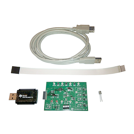
TMP451EVM kit, and Figure 1-1 below shows all of the included hardware. Contact the Texas Instruments Product Information Center nearest you if any component is missing. It is highly recommended that you check the TI website at http://www.ti.com to verify that you have the latest versions of the related software. -
Page 6: Related Documentation From Texas Instruments
The following document provides information regarding Texas Instruments integrated circuits used in the assembly of the TMP451EVM. This user's guide is available from the TI website under literature number SBOU131. Any letter appended to the literature number corresponds to the document revision that is current at the time of the writing of this document. -
Page 7: Tmp451Evm Hardware Setup
10-Pin connector socket used to communicate between the TMP451EVM and the SM-DIG. It should be noted that the TMP451EVM only uses the necessary I communication lines (pins 1 and 3) and the VDUT and GND (pin 6 and 8) pins to issue commands to the TMP451 sensors. -
Page 8: Theory Of Operation For Usb Dig Platform
SM-USB-DIG platform. This platform is a general purpose data acquisition system that is used on several different Texas Instruments evaluation modules. The details of its operation are included in a separate document. The block diagram shown in... -
Page 9: Tmp451Evm Hardware Overview
ESD workstation. Connecting the Hardware To connect the TMP451EVM and the SM-USB-DIG Platform together, gently slide the male and female ends of the 10-pin connectors together. Make sure that the two connectors are completely pushed together; loose connections may cause intermittent operation. -
Page 10: Optional 10-Pin Connector Ribbon Extender
3.3.2 Remote Temperature Terminal Block, J4 The TMP451EVM has a terminal block, J4, used for attaching a remote temperature sensor, in this case a NPN transistor which is included in the kit. To connect the transistor, attach the base and collector to D+... -
Page 11: Connection For Npn Transistor To J4
TMP451EVM Features www.ti.com Figure 3-4. Connection for NPN Transistor to J4 Figure 3-5. Remote NPN Setup SBOU131 – June 2013 TMP451EVM Hardware Overview Submit Documentation Feedback Copyright © 2013, Texas Instruments Incorporated... -
Page 12: Tmp451Evm Software Setup
TMP451EVM Software Installation The TMP451EVM software is included on the CD that is shipped with the EVM kit. It is also available through the TMP451EVM product folder on the TI website. To download the software to your system, insert the disc into an available CD-ROM drive. -
Page 13: Tmp451Evm Software Install Window
Figure 4-2. After accepting the Texas Instruments and National Instruments license agreements, the progress bar opens and shows the installation of the software. Once the installation process is completed click Finish. SBOU131 – June 2013... -
Page 14: Tmp451Evm License Agreements
TMP451EVM Software Installation www.ti.com Figure 4-2. TMP451EVM License Agreements TMP451EVM Software Setup SBOU131 – June 2013 Submit Documentation Feedback Copyright © 2013, Texas Instruments Incorporated... -
Page 15: Tmp451Evm Software Overview
This section discusses how to use the TMP451EVM software. Starting the TMP451EVM Software The TMP451EVM software can be operated through the Start menu in Windows. From the Start menu, select All Programs, highlight the TMP451 folder, and then select the TMP451EVM program. -
Page 16: Using The Tmp451Evm Software
5.2.2 Temperature ALERT and THERM Limits The first tab on the TMP451EVM software is Temperature Limits. In this tab you can read or set the ALERT and THERM limits for the TMP451. You can also set a temperature offset for the remote temperature sensor and enable a THERM hysteresis. -
Page 17: Configuration Register Tab
Figure 5-4. Temperature Limits Tab 5.2.3 Configuration Register Tab The TMP451EVM software contains a tab for the configuration register, consecutive alert register, and status register. Changing values in this register automatically writes them. In the Configuration register the bit MASK1 masks the ALERT pin when enabled. R/S stands for RUN/STOP, when enabled this sets the TMP451 to standby. -
Page 18: Conversion Rate Register Tab
5.2.5 n-Factor Correction Tab The TMP451 allows for a different n-factor value for converting remote channel measurements to temperature. Table 5-2 shows the n-factor correction register codes. TMP451EVM Software Overview SBOU131 – June 2013 Submit Documentation Feedback Copyright © 2013, Texas Instruments Incorporated... -
Page 19: Reading The Temperature Gauge
10000000 –128 0.706542 5.2.6 Reading the Temperature Gauge The temperature box on the TMP451EVM software displays the measured values of the TMP451 device Local Temperature and External Temperature registers in a graphical format as shown in Figure 5-6. These values are displayed in Celsius. A continuous reading can be displayed by toggling the Read Continuously control. -
Page 20: Tmp451Evm Documentation
SBOU131 – June 2013 TMP451EVM Documentation This section contains the complete bill of materials and schematic diagram for the TMP451EVM. Documentation information for the SM-USB-DIG platform can be found in the SM-USB-DIG platform User’s Guide, SBOU098, available at the TI website at http://www.ti.com. -
Page 21: Tmp451Evm Pcb Components Layout
TMP451EVM PCB Components Layout www.ti.com TMP451EVM PCB Components Layout Figure 6-2 shows the layout of the components for the TMP451EVM board. Figure 6-2. TMP451EVM Components Layout SBOU131 – June 2013 TMP451EVM Documentation Submit Documentation Feedback Copyright © 2013, Texas Instruments Incorporated... -
Page 22: Tmp451 Test Board Bill Of Materials
TMP451 Test Board Bill of Materials www.ti.com TMP451 Test Board Bill of Materials Table 6-1 lists the bill of materials for the TMP451EVM Test Board. Table 6-1. TMP451EVM Test Board Bill of Materials Item Value Ref Des Description Manufacture Digi-Key... - Page 23 TMP451 Test Board Bill of Materials www.ti.com Table 6-1. TMP451EVM Test Board Bill of Materials (continued) Item Value Ref Des Description Manufacture Digi-Key Manufactur Unit Notes Part No. er Part No. Price Price R3, R4, RES, 10 kΩ, 1%, 0.1...
- Page 24 Any exceptions to this are strictly prohibited and unauthorized by Texas Instruments unless user has obtained appropriate experimental/development licenses from local regulatory authorities, which is responsibility of user including its acceptable authorization.
- Page 25 FCC Interference Statement for Class B EVM devices This equipment has been tested and found to comply with the limits for a Class B digital device, pursuant to part 15 of the FCC Rules. These limits are designed to provide reasonable protection against harmful interference in a residential installation. This equipment generates, uses and can radiate radio frequency energy and, if not installed and used in accordance with the instructions, may cause harmful interference to radio communications.
- Page 26 Also, please do not transfer this product, unless you give the same notice above to the transferee. Please note that if you could not follow the instructions above, you will be subject to penalties of Radio Law of Japan. Texas Instruments Japan Limited (address) 24-1, Nishi-Shinjuku 6 chome, Shinjuku-ku, Tokyo, Japan http://www.tij.co.jp...
- Page 27 FDA Class III or similar classification, then you must specifically notify TI of such intent and enter into a separate Assurance and Indemnity Agreement. Mailing Address: Texas Instruments, Post Office Box 655303, Dallas, Texas 75265 Copyright © 2013, Texas Instruments Incorporated...
- Page 28 IMPORTANT NOTICE Texas Instruments Incorporated and its subsidiaries (TI) reserve the right to make corrections, enhancements, improvements and other changes to its semiconductor products and services per JESD46, latest issue, and to discontinue any product or service per JESD48, latest issue.
- Page 29 Mouser Electronics Authorized Distributor Click to View Pricing, Inventory, Delivery & Lifecycle Information: Texas Instruments TMP451EVM...
Need help?
Do you have a question about the TMP451EVM and is the answer not in the manual?
Questions and answers