Table of Contents
Advertisement
Quick Links
TMP104EVM Evaluation Board and Software Tutorial
This user's guide describes the characteristics, operation, and use of the TMP104EVM evaluation board. It
discusses how to set up and configure the software and hardware and reviews various aspects of the
program operation. Throughout this document, the terms evaluation board, evaluation module, and EVM
are synonymous with the TMP104EVM. This user's guide also includes information regarding operating
procedures and input/output connections, an electrical schematic, printed circuit board (PCB) layout
drawings, and a parts list for the EVM.
.....................................................................................................................
1
2
3
4
5
6
1
2
TMP104EVM Hardware Setup
3
4
5
6
7
8
9
10
11
12
13
14
....................................................................................................................
15
16
17
18
19
20
Microsoft, Windows are registered trademarks of Microsoft Corporation.
2
I
C is a trademark of NXP Semiconductors.
WinZIP is a registered trademark of WinZip International LLC.
All other trademarks are the property of their respective owners.
SBOU118 - October 2011
Submit Documentation Feedback
............................................................................................
....................................................................................................
.....................................................................................................
.......................................................................................
............................................................................................
...............................................................................
............................................................................................
......................................................................................
...................................................................................
.......................................................................................
............................................................................................
.......................................................................................
.......................................................................................
........................................................................................
......................................................................................................
............................................................................................
..............................................................................................................
.............................................................................................
............................................................................................
................................................................................................
..........................................................................................
Copyright © 2011, Texas Instruments Incorporated
Contents
List of Figures
.............................................................
..........................................................................
..................................................................
TMP104EVM Evaluation Board and Software Tutorial
User's Guide
SBOU118 - October 2011
2
3
6
8
10
17
2
3
4
5
6
6
7
8
9
10
10
11
12
13
14
15
15
16
17
18
1
Advertisement
Table of Contents

Related Manuals for Texas Instruments TMP104EVM


Summary of Contents for Texas Instruments TMP104EVM
-
Page 1: Table Of Contents
SBOU118 – October 2011 TMP104EVM Evaluation Board and Software Tutorial This user's guide describes the characteristics, operation, and use of the TMP104EVM evaluation board. It discusses how to set up and configure the software and hardware and reviews various aspects of the program operation. -
Page 2: Overview
This device is especially ideal for space-constrained, power-sensitive applications with multiple temperature measurement zones that must be monitored. The TMP104EVM is a platform for evaluating the performance of the TMP104 under various signal, reference, and supply conditions. This document gives a general overview of the TMP104EVM and provides a general description of the features and functions to be considered while using this evaluation module. -
Page 3: Tmp104Evm Hardware Setup
The following documents provide information regarding Texas Instruments' integrated circuits used in the assembly of the TMP104EVM. This user's guide is available from the TI web site under literature number SBOU118. Any letter appended to the literature number corresponds to the document revision that is current at the time of the writing of this document. -
Page 4: Tmp104Evm Board Block Diagram
Table 3 shows the pinout for the 10-pin connector socket used to communicate between the TMP104EVM and the SM-USB-DIG. It should be noted that the TMP104EVM uses only the necessary I communication lines (pins 1 and 3) and the V and GND (pins 6 and 8, respectively) to issue commands to the TMP104. -
Page 5: Sm-Usb-Dig Platform Block Diagram
Figure 4 shows the block diagram for the SM-USB-DIG platform. This platform is a general-purpose data acquisition system that is used on several different Texas Instruments evaluation modules. The details of its operation are included in a separate document, SBOU098 (available for download at www.ti.com). -
Page 6: Tmp104Evm Hardware
EVM, including the use of a grounded wrist strap at an approved ESD workstation. Typical Hardware Connections First, connect the TMP104EVM test board to the SM-USB-DIG and then connect the USB cable, as shown in Figure 5. -
Page 7: 10-Pin Ribbon Cable Extender
3.4.3 10-Pin Connector Ribbon Extender (Optional) The TMP104EVM kit ships with an optional ribbon cable for extending the connection between the SM-USB-DIG and the PCB. This extension cable can be useful if high temperature tests must be run on the test board, because the SM-USB-DIG is not rated for high temperatures. To connect the ribbon cable,... -
Page 8: Tmp104Evm Software
States and European regional settings. The software should also function on other Windows OS platforms. Software Installation The TMP104EVM software is included on the CD that is shipped with the EVM kit. It is also available through the TMP104EVM product folder on the TI website. -
Page 9: Tmp104Evm License Agreements
Instruments\. Following this option, two license agreements are presented that must be accepted, as shown in Figure 9. After accepting the Texas Instruments and National Instruments license agreements, the progress bar opens and shows the installation of the software. Once the installation process is completed, click Finish. -
Page 10: Tmp104Evm Software Overview
The TMP104 software can be operated through the Windows Start menu. From Start, select All Programs; then select the TMP104EVM program. Figure 10 illustrates how the software should appear if the TMP104EVM is functioning properly. Figure 10. TMP104EVM Software Interface Figure 11 shows an error message that is displayed if the PC cannot communicate with the EVM. -
Page 11: Tmp104 Initialization
5.2.1 Reading from Registers When first starting the TMP104EVM software, the user should confirm stable connections to the test board by toggling the Power button to provide power to the TMP104. Then, the user should press the Initialize button, as shown in Figure 12. -
Page 12: Tmp104 Writing To Registers
TMP104EVM Software Overview www.ti.com 5.2.2 Writing to Registers The TMP104EVM software contains two different methods for writing data: Write All Reg and Auto-Write Reg, as Figure 13 shows. Figure 13. TMP104 Writing to Registers NOTE: The user cannot simultaneously perform the Read All Registers and Auto-Write Registers functions. -
Page 13: Registers Tab
Help with Reg button, as indicated in Figure Figure 14. Registers Tab SBOU118 – October 2011 TMP104EVM Evaluation Board and Software Tutorial Submit Documentation Feedback Copyright © 2011, Texas Instruments Incorporated... -
Page 14: Interrupts
15. Communication with the TMP104s cannot continue until a Global Clear Interrupt command has been issued by clicking the appropriate button, as indicated in Figure Figure 15. Interrupts SBOU118 – October 2011 TMP104EVM Evaluation Board and Software Tutorial Submit Documentation Feedback Copyright © 2011, Texas Instruments Incorporated... -
Page 15: Changing Conversion Rates
TMP104, cycling through operational modes, and clicking the Write All Reg button, as indicated in Figure Figure 17. Changing Operational Modes SBOU118 – October 2011 TMP104EVM Evaluation Board and Software Tutorial Submit Documentation Feedback Copyright © 2011, Texas Instruments Incorporated... -
Page 16: Temperature Graphs Tab
5.2.6 Temperature Graphs Tab In Continuously Read and Plot All Reg mode, the respective value for each of the local temperature sensors on the TMP104EVM is plotted in degrees Celsius (°C). Figure 18 shows the Temperature Graphs tab. Figure 18. Temperature Graphs Tab SBOU118 –... -
Page 17: Tmp104Evm Documentation
TMP104EVM Documentation This section contains the complete bill of materials and PCB layout for the TMP104EVM. NOTE: These board layouts are not to scale. These image are intended to show how the board is laid out; they are not intended to be used for manufacturing TMP104EVM PCBs. -
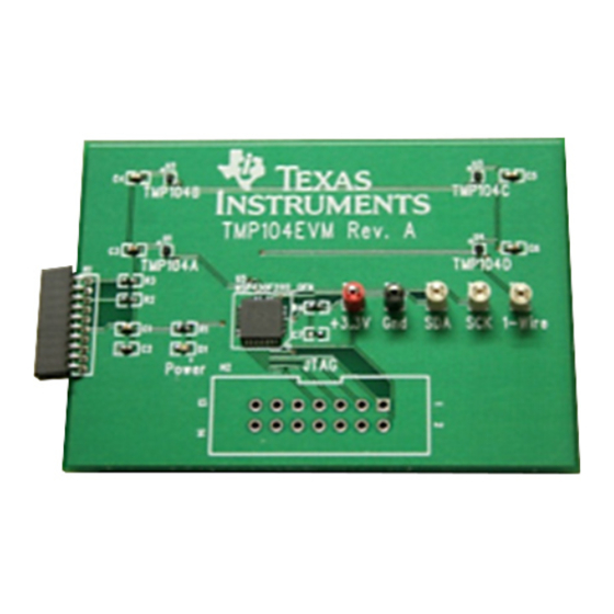
Page 18: Tmp104Evm Pcb Top Layer (Component Layout)
TMP104EVM Documentation www.ti.com PCB Layout Figure 20 shows the PCB layout of the TMP104EVM. Figure 20. TMP104EVM PCB Top Layer (Component Layout) SBOU118 – October 2011 TMP104EVM Evaluation Board and Software Tutorial Submit Documentation Feedback Copyright © 2011, Texas Instruments Incorporated... - Page 19 TMP104EVM Documentation www.ti.com Bill of Materials Table 4 lists the bill of materials for the TMP104EVM. Table 4. TMP104 Test Board Bill of Materials Item Value Ref Des Description Vendor/Mfr Part Number MSP430F2112 IC, MCU, 16-bit, 2K flash 32-QFN Texas Instruments...
- Page 20 Evaluation Board/Kit Important Notice Texas Instruments (TI) provides the enclosed product(s) under the following conditions: This evaluation board/kit is intended for use for ENGINEERING DEVELOPMENT, DEMONSTRATION, OR EVALUATION PURPOSES ONLY and is not considered by TI to be a finished end-product fit for general consumer use. Persons handling the product(s) must have electronics training and observe good engineering practice standards.
- Page 21 Any exceptions to this are strictly prohibited and unauthorized by Texas Instruments unless user has obtained appropriate experimental/development licenses from local regulatory authorities, which is responsibility of user including its acceptable authorization.
- Page 22 FCC Interference Statement for Class B EVM devices This equipment has been tested and found to comply with the limits for a Class B digital device, pursuant to part 15 of the FCC Rules. These limits are designed to provide reasonable protection against harmful interference in a residential installation. This equipment generates, uses and can radiate radio frequency energy and, if not installed and used in accordance with the instructions, may cause harmful interference to radio communications.
- Page 23 Also, please do not transfer this product, unless you give the same notice above to the transferee. Please note that if you could not follow the instructions above, you will be subject to penalties of Radio Law of Japan. Texas Instruments Japan Limited (address) 24-1, Nishi-Shinjuku 6 chome, Shinjuku-ku, Tokyo, Japan http://www.tij.co.jp...
- Page 24 FDA Class III or similar classification, then you must specifically notify TI of such intent and enter into a separate Assurance and Indemnity Agreement. Mailing Address: Texas Instruments, Post Office Box 655303, Dallas, Texas 75265 Copyright © 2012, Texas Instruments Incorporated...
- Page 25 IMPORTANT NOTICE Texas Instruments Incorporated and its subsidiaries (TI) reserve the right to make corrections, enhancements, improvements and other changes to its semiconductor products and services per JESD46, latest issue, and to discontinue any product or service per JESD48, latest issue.
Need help?
Do you have a question about the TMP104EVM and is the answer not in the manual?
Questions and answers