Advertisement
Quick Links
www.ti.com
EVM User's Guide: TMP113
TMP113 Evaluation Module
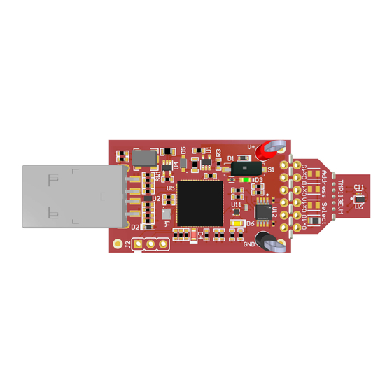
Description
2
The
TMP113
is an I
C-compatible digital temperature
sensor in a 6-pin WCSP package. The TMP113EVM
allows users to evaluate the performance of the
TMP113 digital temperature sensor. The TMP113EVM
is designed to be used as is, along with the
evaluation module GUI. Alternatively, the sensor can
be detached to be evaluated in the user's system.
For this purpose, there are multiple alternatives to
interface with the sensor for best user experience.
Get Started
1. Order the
TMP113EVM
2. Detach the sensor breakout PCB section
(optional)
3. Connect the EVM to computer or user system
4. Go to the
TMP113EVM gallery page
to either download the GUI or run on the web
5. Refer to the
TMP113 data sheet
6. Visit our
E2E forums
SNOU211 – NOVEMBER 2024
Submit Document Feedback
on dev.ti.com
for IC details
for support or questions
TMP113EVM
Copyright © 2024 Texas Instruments Incorporated
Features
•
Easy to use cloud-based GUI is available on the
web or can be downloaded for offline use
•
Showcase the ultra-small digital temperature
sensor with alert functionality
•
Breakable sensor board with 0.1'' pitch header
footprint to interface with the TMP113
•
Data logging with GUI
Applications
•
Building automation
–
Occupancy detection
–
Video doorbell
–
HVAC: Wireless environmental sensor
•
Factory automation & control
–
Machine vision camera
– Power Delivery Units
–
Industrial PC: Single board computer
–
CPU (PLC controller)
•
Medical equipment
–
Continuous glucose monitor
•
Data center & enterprise computing
–
Solid State Drive (SSD)
–
Rack Server Motherboard
•
Personal electronics
–
PC & notebooks, tablets
–
Digital still & video camera
–
Augmented reality glasses
–
Smart speakers
Description
TMP113 Evaluation Module
1
Advertisement

Related Manuals for Texas Instruments TMP113


Summary of Contents for Texas Instruments TMP113
- Page 1 • Showcase the ultra-small digital temperature TMP113 digital temperature sensor. The TMP113EVM sensor with alert functionality is designed to be used as is, along with the •...
- Page 2 The user can connect the TMP113 sensor breakout section to the user's system/host. • The user can connect the EVM host and software to the user's system with TMP113 devices. • Small individual boards allow the user to place sensors in the user's system or in a temperature-controlled environment to evaluate performance.
- Page 3 Evaluation Module Overview 1.4 Device Information The TMP113 is a digital output temperature sensor that is calibrated in production to achieve high accuracy in a small 6-pin WCSP package. This device communicates in a two-wire environment compatible with SMBus and I C interfaces, and has 4 I C address options using the address select pin.
- Page 4 2.2 Perforations and Connectability The perforation between the USB controller and TMP113 sensor breakout section is labeled on the bottom of the board on both sides for pin connections. Once the sensor section is detached from the controller section, the user can interface with the sensor section by soldering wires or 0.1'' header connectors.
- Page 5 1001011 2.5 Power Supply VDD supplies power to the TMP113 device and pullup voltage of the communication lines, and must be set between 1.4V to 5.5V for normal operation of the TMP113EVM. The on-board regulator U1 regulates USB power down to 3.3V. The user can also disable the sub-regulator to apply a different supply voltage. To use an external power supply, follow these instructions: 1.
- Page 6 Gallery Download. Figure 3-1. Download Pop-Up TMP113 Evaluation Module SNOU211 – NOVEMBER 2024 Submit Document Feedback Copyright © 2024 Texas Instruments Incorporated...
- Page 7 Registers and Collateral tabs which are explained below. The icons on the left side of the screen are shortcuts to the tabs. Figure 3-2. Home SNOU211 – NOVEMBER 2024 TMP113 Evaluation Module Submit Document Feedback Copyright © 2024 Texas Instruments Incorporated...
- Page 8 Then, click the button on the bottom left of the GUI to reinitialize communication. Figure 3-3. Getting Started TMP113 Evaluation Module SNOU211 – NOVEMBER 2024 Submit Document Feedback Copyright © 2024 Texas Instruments Incorporated...
- Page 9 Software 3.4 Information Tab The Information tab shows device details and features of the TMP113 and EVM. The Device Information & Features sub-tab includes a specifications summary, device block diagram, and description of functional modes. The EVM Details sub-tab includes the EVM schematic and legend.
- Page 10 Start button and the data (CSV) automatically exports once the stop button is clicked. The Alert Config box allows the user to easily configure the alert functionality settings of the TMP113 such as polarity, mode, and limits. The limits can be written on the left box in decimal format, and the corresponding hexadecimal value is automatically displayed in the right box for reference.
- Page 11 Software 3.6 Registers Tab The Registers tab interacts with the registers and bits within the TMP113 device. For more information on each register/bit, click on a register name to see what each bit defines. The Auto Read dropdown box configures the polling rate of the register contents. By default, the MCU polls the registers with a 100ms delay.
- Page 12 The Collateral tab contains links to the EVM user's guide, the tool page on ti.com, as well as links to the product data sheet and other relevant links. Figure 3-7. Collateral TMP113 Evaluation Module SNOU211 – NOVEMBER 2024 Submit Document Feedback Copyright © 2024 Texas Instruments Incorporated...
- Page 13 Yellow P5.4/XIN P6.4/CB4/A4 VCCA: 0.9-5.5V P5.5/XOUT P6.5/CB5/A5 VCCB: 2.7-5.5V P6.6/CB6/A6 P6.7/CB7/A7 PU.0/DP PJ.0/TDO PU.1/DM PJ.1/TDI/TCLK PJ.2/TMS 33.0k PJ.3/TCK TMP113 Device - Breakable Section SBWTDIO RST/NMI/SBWTDIO VCORE SBWTCK Address Selection VCORE TEST/SBWTCK VBUS QFN PAD VUSB 2200pF VSSU AVSS1 AVCC1 AVSS2...
- Page 14 Hardware Design Files www.ti.com 4.2 PCB Layouts Figure 4-2. Top View Figure 4-3. Bottom View TMP113 Evaluation Module SNOU211 – NOVEMBER 2024 Submit Document Feedback Copyright © 2024 Texas Instruments Incorporated...
- Page 15 R1, R2 ERJ-2GEJ220X Panasonic 0402 22Ω AEC-Q200 Grade 0, 0402 RES, 100 k, 5%, 0.1 W, ERJ-2GEJ104X Panasonic 0402 100kΩ AEC-Q200 Grade 0, 0402 SNOU211 – NOVEMBER 2024 TMP113 Evaluation Module Submit Document Feedback Copyright © 2024 Texas Instruments Incorporated...
- Page 16 -40 to 125 degC, Green (RoHS & no Sb/Br) 4-Channel ESD TPD4E004DRYR Texas Instruments DRY0006A Protection Array for High- Speed Data Interfaces, DRY0006A (USON-6) TMP113 Evaluation Module SNOU211 – NOVEMBER 2024 Submit Document Feedback Copyright © 2024 Texas Instruments Incorporated...
- Page 17 Sullins Connector Header, 2.54 mm, 3x1, Gold, TH Solutions Thick Film Chip Resistors R02, R03, R04 CR0805-J/-000ELF Bourns 0805 0Ω 0805 0Ω 0.125W 5% SNOU211 – NOVEMBER 2024 TMP113 Evaluation Module Submit Document Feedback Copyright © 2024 Texas Instruments Incorporated...
- Page 18 Apple Inc. Linux ® is a registered trademark of Linus Torvalds. All trademarks are the property of their respective owners. TMP113 Evaluation Module SNOU211 – NOVEMBER 2024 Submit Document Feedback Copyright © 2024 Texas Instruments Incorporated...
- Page 19 STANDARD TERMS FOR EVALUATION MODULES Delivery: TI delivers TI evaluation boards, kits, or modules, including any accompanying demonstration software, components, and/or documentation which may be provided together or separately (collectively, an “EVM” or “EVMs”) to the User (“User”) in accordance with the terms set forth herein.
- Page 20 www.ti.com Regulatory Notices: 3.1 United States 3.1.1 Notice applicable to EVMs not FCC-Approved: FCC NOTICE: This kit is designed to allow product developers to evaluate electronic components, circuitry, or software associated with the kit to determine whether to incorporate such items in a finished product and software developers to write software applications for use with the end product.
- Page 21 www.ti.com Concernant les EVMs avec antennes détachables Conformément à la réglementation d'Industrie Canada, le présent émetteur radio peut fonctionner avec une antenne d'un type et d'un gain maximal (ou inférieur) approuvé pour l'émetteur par Industrie Canada. Dans le but de réduire les risques de brouillage radioélectrique à...
- Page 22 www.ti.com EVM Use Restrictions and Warnings: 4.1 EVMS ARE NOT FOR USE IN FUNCTIONAL SAFETY AND/OR SAFETY CRITICAL EVALUATIONS, INCLUDING BUT NOT LIMITED TO EVALUATIONS OF LIFE SUPPORT APPLICATIONS. 4.2 User must read and apply the user guide and other available documentation provided by TI regarding the EVM prior to handling or using the EVM, including without limitation any warning or restriction notices.
- Page 23 Notwithstanding the foregoing, any judgment may be enforced in any United States or foreign court, and TI may seek injunctive relief in any United States or foreign court. Mailing Address: Texas Instruments, Post Office Box 655303, Dallas, Texas 75265 Copyright © 2023, Texas Instruments Incorporated...
- Page 24 TI products. TI’s provision of these resources does not expand or otherwise alter TI’s applicable warranties or warranty disclaimers for TI products. TI objects to and rejects any additional or different terms you may have proposed. IMPORTANT NOTICE Mailing Address: Texas Instruments, Post Office Box 655303, Dallas, Texas 75265 Copyright © 2024, Texas Instruments Incorporated...
Need help?
Do you have a question about the TMP113 and is the answer not in the manual?
Questions and answers