Perkins 1103 Operation And Maintenance Manual
Industrial engines
Hide thumbs
Also See for 1103:
- Disassembly and assembly (136 pages) ,
- Operation and maintenance manual (92 pages) ,
- Workshop manual (54 pages)
Chapters
Table of Contents

Related Manuals for Perkins 1103


Summary of Contents for Perkins 1103
- Page 1 SEBU7833-03 September 2008 Operation and Maintenance Manual 1103 and 1104 Industrial Engines DC (Engine) DD (Engine) DJ (Engine) DK (Engine) RE (Engine) RG (Engine) RJ (Engine) RR (Engine) RS (Engine) RT (Engine) DF (Engine) DG (Engine)
- Page 2 These changes can affect the service that is given to the product. Obtain the complete and most current information before you start any job. Perkins dealers or Perkins distributors have the most current information available. When replacement parts are required for this product Perkins recommends using Perkins replacement parts.
-
Page 3: Table Of Contents
SEBU7833-03 Table of Contents Table of Contents Foreword ..............4 Safety Section Safety Messages ............ 5 General Hazard Information ........6 Burn Prevention ............7 Fire Prevention and Explosion Prevention ....8 Crushing Prevention and Cutting Prevention ..10 Mounting and Dismounting ........10 Before Starting Engine .......... -
Page 4: Foreword
They assist with developing the skills and Perkins authorized personnel. Your Perkins dealer techniques required to operate the engine more or your Perkins distributor offers a variety of options efficiently and economically. Skill and techniques regarding overhaul programs. If you experience... -
Page 5: Safety Section
If a warning sign is attached to a part of the engine that is replaced, install a new warning sign on the replacement part. Perkins dealers or Perkins distributors can provide new warning signs. Do not work on the engine and do not operate the engine unless the instructions and warnings in the Operation and Maintenance Manual are understood. -
Page 6: General Hazard Information
SEBU7833-03 Safety Section General Hazard Information i02328435 General Hazard Information g01682820 Illustration 3 The ether warning label (2) is located on the cover of the inlet manifold. Refer to illustration 4. g00104545 Illustration 5 Attach a “Do Not Operate” warning tag or a similar warning tag to the start switch or to the controls before you service the equipment or before you repair the equipment. -
Page 7: Burn Prevention
SEBU7833-03 Safety Section Burn Prevention Report all necessary repairs. Do not allow unauthorized personnel on the equipment. Ensure that the power supply is disconnected before you work on the bus bar or the glow plugs. Perform maintenance on the engine with the equipment in the servicing position. -
Page 8: Fire Prevention And Explosion Prevention
If the application involves the presence of combustible Cooling system conditioner contains alkali. Alkali can gases, consult your Perkins dealer and/or your cause personal injury. Do not allow alkali to contact Perkins distributor for additional information about the skin, the eyes, or the mouth. - Page 9 SEBU7833-03 Safety Section Fire Prevention and Explosion Prevention Arcing or sparking could cause a fire. Secure connections, recommended wiring, and correctly maintained battery cables will help to prevent arcing or sparking. Inspect all lines and hoses for wear or for deterioration.
-
Page 10: Crushing Prevention And Cutting Prevention
Crushing Prevention and Cutting Prevention Repair any lines that are loose or damaged. Leaks i01372247 can cause fires. Consult your Perkins dealer or your Mounting and Dismounting Perkins distributor for repair or for replacement parts. Check lines, tubes and hoses carefully. Do not use your bare hand to check for leaks. -
Page 11: Engine Starting
SEBU7833-03 Safety Section Engine Starting Do not bypass the automatic shutoff circuits. Do not Note: The engine is equipped with an automatic disable the automatic shutoff circuits. The circuits are device for cold starting for normal conditions of provided in order to help prevent personal injury. The operation. - Page 12 SEBU7833-03 Safety Section Electrical System Check the electrical wires daily for wires that are loose or frayed. Tighten all loose electrical wires before the engine is started. Repair all frayed electrical wires before the engine is started. See the Operation and Maintenance Manual for specific starting instructions.
-
Page 13: Product Information Section
SEBU7833-03 Product Information Section Model Views Product Information Section Model Views i01928892 Model View Illustrations 1104 Engine Model Views g01012280 Illustration 11 (1) Valve mechanism cover (4) Fuel injection pump (7) Water pump (2) Crankcase breather (5) Engine oil filter (8) Fan pulley (3) Fuel filter (6) Crankshaft pulley... - Page 14 SEBU7833-03 Product Information Section Model Views g01012281 Illustration 12 (1) Oil filler cap (4) Turbocharger (7) Flywheel (2) Exhaust manifold (5) Starter motor (8) Air intake (3) Alternator (6) Flywheel housing...
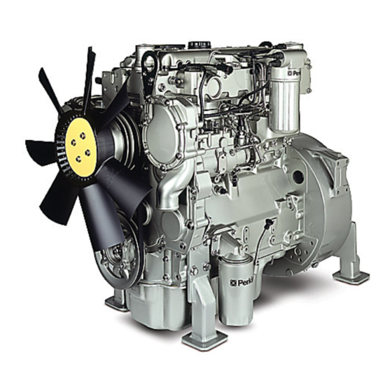
- Page 15 SEBU7833-03 Product Information Section Model Views 1103 Engine Model Views g01011348 Illustration 13 (1) Alternator (3) Turbocharger oil supply (5) Turbocharger (2) Fan pulley (4) Turbocharger oil drain (6) exhaust manifold...
- Page 16 Note: The front end of the engine is opposite the flywheel end of the engine. The left and the right Perkins Engines are designed for the following sides of the engine are determined from the flywheel applications: machine, genset, and industrial mobile end.
- Page 17 SEBU7833-03 Product Information Section Model Views Table 2 1103 Industrial Engine Specifications Number of Cylinders 3 In-Line Bore 105 mm (4.134 inch) Stroke 127 mm (5.0 inch) Aspiration Turbocharged Naturally aspirated Compression Ratio NA 19.25:1 T 18.25:1 Displacement 3.3 L (201 in...
- Page 18 SEBU7833-03 Product Information Section Model Views Engine Service Life Table 4 1103 Genset Specifications Engine efficiency and maximum utilization of engine Number of Cylinders 3 In-Line performance depend on the adherence to proper operation and maintenance recommendations. In Bore 105 mm (4.134 inch)
-
Page 19: Product Identification Information
Information i02280116 Engine Identification Perkins engines are identified by a serial number. This number is shown on a serial number plate that is mounted on the left hand side of the engine block. An example of an engine number is RE12345U090001H. - Page 20 SEBU7833-03 Product Information Section Product Identification Information Engine Full Load rpm _________ ____________________________ Primary Fuel Filter _________ ________________________________ Water Separator Element _________ _______________________ Secondary Fuel Filter Element _________ _________________ Lubrication Oil Filter Element _________ __________________ Auxiliary Oil Filter Element _________ ______________________ Total Lubrication System Capacity _________ ____________ Total Cooling System Capacity...
- Page 21 SEBU7833-03 Product Information Section Product Identification Information g01173630 Illustration 17 This typical example of a label is installed on engines that have electronic fuel injection systems and installed on engines that have electronic fuel injection pumps. g01156733 Illustration 18 This typical example of a label is installed on engines that have mechanical fuel injection pumps.
- Page 22 SEBU7833-03 Product Information Section Product Identification Information Label for engines that comply with MSHA emissions g01381316 Illustration 19 Typical example The label that is shown in illustration 19 is for engines that operate in underground coal mines in North America. The label is installed on engines that comply with the Mine Safety and Health Administration (MSHA) emissions.
- Page 23 SEBU7833-03 Product Information Section Product Identification Information g01157127 Illustration 21 This typical example of a label is installed on engines that are stationary engines.
-
Page 24: Operation Section
Engine Lifting fixtures obsolete. If alterations are made, ensure that correct lifting devices are provided. Consult your Perkins dealer or your Perkins distributor for information regarding fixtures for correct engine lifting. i01930351... - Page 25 Note: Certain corrosion inhibitors could cause following guidelines: damage to some engine components. Contact the Service Department of Perkins for advice. NOTICE Do not drain the coolant while the engine is still hot and 8. Operate the engine for a short period in order to...
- Page 26 When the engine protection has been completed in accordance with these instructions, this ensures that no corrosion will occur. Perkins are not responsible for damage which may occur when an engine is in storage after a period in service.
-
Page 27: Gauges And Indicators
Determine and correct the cause of any significant change in the readings. Consult your Perkins dealer or your Perkins distributor for assistance. Ammeter – This gauge indicates the amount of charge or discharge in the battery charging circuit. -
Page 28: Engine Starting
SEBU7833-03 Operation Section Engine Starting Engine Starting • Do not start the engine or move any of the controls if there is a “DO NOT OPERATE” warning tag or similar warning tag attached to the start switch or to the controls. i02194223 Before Starting Engine •... - Page 29 SEBU7833-03 Operation Section Engine Starting When Group 2 diesel fuel is used, the following items i02198348 provide a means of minimizing starting problems Starting the Engine and fuel problems in cold weather: engine oil pan heaters, jacket water heaters, fuel heaters, and fuel line insulation.
- Page 30 SEBU7833-03 Operation Section Engine Starting 3. Connect one negative end of the jump start cable i02177935 to the negative cable terminal of the electrical Starting with Jump Start source. Connect the other negative end of the Cables jump start cable to the engine block or to the chassis ground.
-
Page 31: Engine Operation
Fuel Conservation Practices i02176671 Engine Operation The efficiency of the engine can affect the fuel economy. Perkins design and technology in manufacturing provides maximum fuel efficiency in all applications. Follow the recommended procedures Correct operation and maintenance are key factors... -
Page 32: Engine Stopping
SEBU7833-03 Operation Section Engine Stopping Engine Stopping i01903608 After Stopping Engine i01929389 Stopping the Engine Note: Before you check the engine oil, do not operate the engine for at least 10 minutes in order to allow the engine oil to return to the oil pan. NOTICE •... -
Page 33: Cold Weather Operation
“Starting with Jump Start Cables.” for instructions. Recommendations from your Perkins dealer or Viscosity of the Engine Lubrication your Perkins distributor are based on past proven practices. The information that is contained in this section provides guidelines for cold weather operation. - Page 34 This fuel and oil causes soft carbon deposits to form on the valve stems. Note: Perkins discourages the use of all air flow Generally, the deposits do not cause problems and restriction devices such as radiator shutters.
- Page 35 Fuel and the Effect from Cold Weather Note: Group 3 fuels reduce the life of the engine. The use of Group 3 fuels is not covered by the Perkins warranty. Group 3 fuels include Low Temperature Fuels and Note: Only use grades of fuel that are recommended Aviation Kerosene Fuels.
- Page 36 SEBU7833-03 Operation Section Cold Weather Operation i01903588 Fuel Related Components in Cold Weather Fuel Tanks Condensation can form in partially filled fuel tanks. Top off the fuel tanks after you operate the engine. Fuel tanks should contain some provision for draining water and sediment from the bottom of the tanks.
-
Page 37: Maintenance Section
OEM specifications for the capacity of the auxiliary oil filter. External cooling System capacity (OEM recommendation) 1103 Engine Total Cooling System Table 6 The external cooling system includes a radiator or an expansion tank with the following components: heat exchanger, 1103 Engine aftercooler, and piping. - Page 38 CC, CD Fluid Recommendations CF-2 CD-2 The classifications CD-2 and American Petroleum Institute CF-2 are for two-cycle diesel engines. Perkins does not sell engines that utilize CD-2 and API CF-2 oils. General Lubricant Information Terminology Because of government regulations regarding the Certain abbreviations follow the nomenclature of certification of exhaust emissions from the engine,...
- Page 39 API CH-4 oils may be • EMA DHD-1 multigrade oil (preferred oil) used in Perkins engines that use API CG-4 and API CF-4 oils. API CH-4 oils will generally exceed the • API CH-4 multigrade oil (preferred oil)
- Page 40 SEBU7833-03 Maintenance Section Refill Capacities Table 12 NOTICE Percentage of Sulfur in Oil change interval Failure to follow these oil recommendations can cause the fuel shortened engine service life due to deposits and/or Lower than 0.5 Normal excessive wear. 0.5 to 1.0 0.75 of normal Total Base Number (TBN) and Fuel Sulfur Greater than 1.0...
- Page 41 Aftermarket Oil Additives Re-refined base stock oil Perkins does not recommend the use of aftermarket Re-refined base stock oil are acceptable for use in additives in oil. It is not necessary to use aftermarket Perkins engines if these oils meet the performance additives in order to achieve the engine’s maximum...
- Page 42 Group 2 (permissible fuels) To get the correct power and performance from the engine, use a fuel of the correct quality. The • Group 3 (aviation kerosene fuels) recommended fuel specification for Perkins engines is shown below: • Other fuels •...
- Page 43 Table 14 “JP5 MIL T5624 (Avcat FSII, NATO F44” Perkins Specifications for Distillate Diesel Fuel “JP8 T83133 (Avtur FSII, NATO F34” Specifications Requirements ASTM Test...
- Page 44 (Table 14, contd) NOTICE Copper Strip No. 3 maximum “D130” Operating with fuels that do not meet the Perkins rec- Corrosion ommendations can cause the following effects: Start- 10% at 282 °C ing difficulty, poor combustion, deposits in the fuel in- (540 °F)
- Page 45 Table Never add coolant to an overheated engine. Engine damage could result. Allow the engine to cool first. Table 16 Perkins Minimum Acceptable Water Requirements NOTICE If the engine is to be stored in, or shipped to an area Property...
- Page 46 NOTICE to seasonal variations consult your Perkins dealer Do not use propylene glycol in concentrations that ex- or your Perkins distributor for the correct level of ceed 50 percent glycol because of propylene glycol’s protection. reduced heat transfer capability. Use ethylene glycol...
- Page 47 6000 service hours or Containers of several sizes are available. Consult one half of the ELC service life. your Perkins dealer or your Perkins distributor for the part numbers. ELC is available in a 1:1 premixed cooling solution with distilled water.
- Page 48 8. Repeat Steps 6 and 7 until the system is completely clean. To change from heavy-duty coolant/antifreeze to the Perkins ELC, perform the following steps: 9. Fill the cooling system with the Perkins Premixed ELC. NOTICE Care must be taken to ensure that all fluids are...
- Page 49 Check the coolant/antifreeze (glycol concentration) in order to ensure adequate protection against Test the coolant/antifreeze periodically for the boiling or freezing. Perkins recommends the use of a concentration of SCA. For the interval, refer to the refractometer for checking the glycol concentration.
- Page 50 Maintenance Section Refill Capacities Cleaning the System of Heavy-Duty Coolant/Antifreeze Perkins cooling system cleaners are designed to clean the cooling system of harmful scale and corrosion. Perkins cooling system cleaners dissolve mineral scale, corrosion products, light oil contamination and sludge.
-
Page 51: Maintenance Interval Schedule
SEBU7833-03 Maintenance Section Maintenance Interval Schedule Every 2 Years i03302982 Maintenance Interval Schedule Cooling System Coolant - Change ....... 58 Every 3000 Service Hours Fuel Injector - Test/Change ........68 When Required Battery - Replace ..........54 Every 3000 Service Hours or 2 Years Battery or Battery Cable - Disconnect .... -
Page 52: Every 2000 Service Hours Aftercooler Core - Inspect
SEBU7833-03 Maintenance Section Aftercooler Core - Clean/Test i02322260 Aftercooler Core - Clean/Test Personal injury can result from air pressure. Personal injury can result without following prop- er procedure. When using pressure air, wear a pro- 1. Remove the core. Refer to the OEM information tective face shield and protective clothing. -
Page 53: Alternator And Fan Belts - Inspect/Adjust/Replace
Make repairs, if necessary. i02322311 Alternator - Inspect Perkins recommends a scheduled inspection of the alternator. Inspect the alternator for loose connections and correct battery charging. Check the ammeter (if equipped) during engine operation in... -
Page 54: Battery - Replace
SEBU7833-03 Maintenance Section Battery - Replace 2. Move the alternator in order to increase or 5. Remove the used battery. decrease the belt tension. Tighten the alternator pivot bolt and the link bolt to 22 N·m (16 lb ft).(1). 6. Install the new battery. Note: Before the cables are connected, ensure that Replacement the engine start switch is OFF. -
Page 55: Battery Or Battery Cable - Disconnect
SEBU7833-03 Maintenance Section Battery or Battery Cable - Disconnect i02323088 i02203590 Battery or Battery Cable - Cooling System Coolant (Commercial Heavy-Duty) - Disconnect Change NOTICE The battery cables or the batteries should not be Care must be taken to ensure that fluids are contained removed with the battery cover in place. - Page 56 filler cap. for reuse in engine cooling systems. The full distillation procedure is the only method acceptable by Perkins to 3. Start and run the engine at low idle. Increase the reclaim the coolant.
-
Page 57: Every 12 000 Service Hours Or 6 Years Cooling System Coolant (Elc) - Change
The full distillation • Foaming is observed. procedure is the only method acceptable by Perkins to reclaim the coolant. • The oil has entered the cooling system and the coolant is contaminated. -
Page 58: Cooling System Coolant - Change
Note: The radiator may not have been provided by engine rpm to high idle. Run the engine at high Perkins. The following is a general procedure for idle for one minute in order to purge the air from changing the coolant. Refer to the OEM information the cavities of the engine block. -
Page 59: Cooling System Coolant Level - Check
Extender (ELC) - Add Pressurized System: Hot coolant can cause seri- The Perkins Extended Life Coolant (ELC) does not ous burns. To open the cooling system filler cap, need the frequent addition of Supplemental Coolant... -
Page 60: Engine - Clean
SEBU7833-03 Maintenance Section Driven Equipment - Check • Lubrication • Other maintenance recommendations Perform any maintenance for the driven equipment which is recommended by the OEM. i01930350 Engine - Clean g00285520 Illustration 32 Personal injury or death can result from high volt- Cooling system filler cap age. -
Page 61: Engine Air Cleaner Element (Dual Element) - Clean/Replace
Servicing the Air Cleaner Elements Note: The air filter system may not have been provided by Perkins. The procedure that follows is for a typical air filter system. Refer to the OEM information for the correct procedure. - Page 62 SEBU7833-03 Maintenance Section Engine Air Cleaner Element (Dual Element) - Clean/Replace Cleaning the Primary Air Cleaner Elements NOTICE Observe the following guidelines if you attempt to clean the filter element: Do not tap or strike the filter element in order to re- move dust.
-
Page 63: Engine Air Cleaner Element (Single Element)
SEBU7833-03 Maintenance Section Engine Air Cleaner Element (Single Element) - Inspect/Replace Inspect the clean, dry primary air cleaner element. Some engines are equipped with a differential gauge Use a 60 watt blue light in a dark room or in a similar for inlet air pressure. -
Page 64: Engine Oil Sample - Obtain
Engine Ground - Inspect/Clean Inspect the wiring harness for good connections. Perkins use the starter motor in order to ground the engine. Check the connection on the starter motor at every oil change. Ground wires and straps should be combined at engine grounds. -
Page 65: Engine Oil And Filter - Change
SEBU7833-03 Maintenance Section Engine Oil and Filter - Change Perkins recommends using a sampling valve in order i01929323 to obtain oil samples. The quality and the consistency Engine Oil and Filter - Change of the samples are better when a sampling valve is used. - Page 66 fications. Use of an oil filter that is not recommended g01003628 Illustration 39 by Perkins could result in severe damage to the en- gine bearings, crankshaft, etc., as a result of the larger (2) Filter head (3) O ring seal waste particles from unfiltered oil entering the engine...
-
Page 67: Every 1000 Service Hours Engine Valve Lash - Inspect/Adjust
Refer to the Operation and maintenance. Refer to the Service Manual or your au- Maintenance Manual for more information on refill thorized Perkins dealer or your Perkins distributor for capacities. the complete valve lash adjustment procedure. -
Page 68: Fuel Injector - Test/Change
SEBU7833-03 Maintenance Section Fuel Injector - Test/Change Ensure that the engine can not be started while this maintenance is being performed. To help pre- vent possible injury, do not use the starting motor to turn the flywheel. Hot engine components can cause burns. Allow additional time for the engine to cool before mea- suring/adjusting valve lash clearance. -
Page 69: Fuel System - Prime
The fuel tank is empty or the fuel tank has been partially drained. Note: In order to purge air from the fuel injection pump on Perkins engines with a fixed throttle, the • The low pressure fuel lines are disconnected. -
Page 70: Fuel System Primary Filter/Water Separator - Drain
SEBU7833-03 Maintenance Section Fuel System Primary Filter (Water Separator) Element - Replace 2. Place a suitable container under the water i02206563 separator. Clean the outside of the water Fuel System Primary Filter separator. (Water Separator) Element - 3. Open the drain (5). Allow the fluid to drain into Replace the container. -
Page 71: Fuel System Secondary Filter - Replace
SEBU7833-03 Maintenance Section Fuel System Secondary Filter - Replace NOTICE Do not allow dirt to enter the fuel system. Thoroughly clean the area around a fuel system component that will be disconnected. Fit a suitable cover over discon- nected fuel system component. Element filter Turn the valves for the fuel lines (if equipped) to the OFF position before performing this maintenance. - Page 72 SEBU7833-03 Maintenance Section Fuel System Secondary Filter - Replace g01010595 Illustration 48 (3) O ring seal (4) Element (5) Filter head 3. Remove the filter bowl (2) from the filter head (5). Press on the element (4). Rotate the element g01121396 counterclockwise in order to release the element Illustration 49...
-
Page 73: Every 50 Service Hours Or Weekly Fuel Tank Water And Sediment - Drain
SEBU7833-03 Maintenance Section Fuel Tank Water and Sediment - Drain Water can be introduced into the fuel tank when the fuel tank is being filled. Condensation occurs during the heating and cooling of fuel. The condensation occurs as the fuel passes through the fuel system and the fuel returns to the fuel tank. -
Page 74: Hoses And Clamps - Inspect/Replace
(if equipped). • Cracking The coolant system and the hoses for the coolant system are not usually supplied by Perkins. The • Softness following text describes a typical method of replacing coolant hoses. Refer to the OEM information for •... -
Page 75: Severe Service Application - Check
“comb”. Inspect these items for good condition: Radiator - Clean Welds, mounting brackets, air lines, connections, clamps, and seals. Make repairs, if necessary. The radiator is not usually supplied by Perkins. The i02335775 following text describes a typical cleaning procedure Severe Service Application - for the radiator. -
Page 76: Starting Motor - Inspect
Test” for more information on the checking procedure cold environments or hot environments. Valve components can be damaged by carbon buildup if and for specifications or consult your Perkins dealer the engine is frequently started and stopped in very or your Perkins distributor for assistance. -
Page 77: Walk-Around Inspection
Disassembly and Assembly 4. Fasten the air intake pipe and the exhaust outlet Manual, “Water Pump - Remove and Install” for more pipe to the turbocharger housing. information or consult your Perkins dealer or your Perkins distributor. i02177973 •... -
Page 78: Water Pump - Inspect
SEBU7833-03 Maintenance Section Water Pump - Inspect Belts for multiple groove pulleys must be replaced as matched sets. If only one belt is replaced, the belt will carry more load than the belts that are not replaced. The older belts are stretched. The additional load on the new belt could cause the belt to break. -
Page 79: Warranty Section
Emissions Warranty. Consult your authorized Perkins dealer or your authorized Perkins distributor in order to determine if your engine is emissions certified and if your engine is subject to an Emissions Warranty. -
Page 80: Index
SEBU7833-03 Index Section Index Electrical System ............ 11 After Starting Engine ..........30 After Stopping Engine..........32 Grounding Practices .......... 12 Aftercooler Core - Clean/Test ........ 52 Emergency Stopping ..........32 Aftercooler Core - Inspect........52 Emissions Certification Film ........20 Alternator - Inspect .......... - Page 81 Maintenance Interval Schedule ......51 Engine Oil ............39 Maintenance Section ..........37 Fuel Specifications..........42 Model View Illustrations......... 13 1103 Engine Model Views........15 General Lubricant Information ......38 1104 Engine Model Views........13 Foreword ..............4 California Proposition 65 Warning ....... 4 Model Views ............
- Page 82 SEBU7833-03 Index Section Walk-Around Inspection ........77 Inspect the Engine for Leaks and for Loose Connections ............. 77 Warranty Information ..........79 Warranty Section ........... 79 Water Pump - Inspect..........78...
- Page 83 Product and Dealer Information Note: For product identification plate locations, see the section “Product Identification Information” in the Operation and Maintenance Manual. Delivery Date: Product Information Model: Product Identification Number: Engine Serial Number: Transmission Serial Number: Generator Serial Number: Attachment Serial Numbers: Attachment Information: Customer Equipment Number: Dealer Equipment Number:...
- Page 84 Copyright © 2008 Perkins Engines Company Limited Printed in U.K. All Rights Reserved...
Need help?
Do you have a question about the 1103 and is the answer not in the manual?
Questions and answers