Perkins 1106D Operation And Maintenance Manual
Industrial engine
Hide thumbs
Also See for 1106D:
- Troubleshooting manual (216 pages) ,
- Disassembly and assembly (180 pages) ,
- Troubleshooting manual (180 pages)

Related Manuals for Perkins 1106D


Summary of Contents for Perkins 1106D
- Page 1 SEBU8119-04 (en-us) January 2021 Operation and Maintenance Manual 1106D Industrial Engine PJ (Engine)
- Page 2 If a tool, procedure, work method or operating technique that is not specifically recommended by Perkins is used, you must satisfy yourself that it is safe for you and for others. You should also ensure that you are authorized to perform this work, and that the product will not be damaged or become unsafe by the operation, lubrication, maintenance or repair procedures that you intend to use.
-
Page 3: Table Of Contents
SEBU8119-04 Table of Contents Table of Contents Engine Stopping ..........45 Cold Weather Operation ......... 47 Foreword ............4 Maintenance Section Safety Section Refill Capacities..........51 Safety Messages..........6 Maintenance Interval Schedule....... 66 General Hazard Information......9 Warranty Section Burn Prevention..........12 Warranty Information........ -
Page 4: Foreword
State of arises regarding your engine, or this manual, please California to cause cancer, birth defects, consult with your Perkins dealer or your Perkins distributor for the latest available information. and other reproductive harm. WARNING – This product can... - Page 5 Perkins distributor offers various options regarding overhaul programs. If you experience a major engine failure, there are also numerous after failure overhaul options available. Consult with your Perkins dealer or your Perkins distributor for information regarding these options.
-
Page 6: Safety Section
Replace any warning sign that is damaged or missing. If a warning sign is attached to a part of the engine that is replaced, install a new warning sign on the replacement part. Your Perkins distributor can provide new warning signs. (1) Universal Warning... - Page 7 SEBU8119-04 Safety Section Safety Messages Illustration 2 g01392790 Location of label (1) Universal warning (2) Ether Warning Do not use aerosol types of starting aids such as ether. Such use could result in an explosion and personal injury. Illustration 3 g01154809 Typical example The ether warning label (2) is located on the cover of...
- Page 8 SEBU8119-04 Safety Section Safety Messages Illustration 4 g01392789 Location of labels (2) Ether (3) Hand (High Pressure) (3) Hand (High Pressure) Contact with high pressure fuel may cause fluid penetration and burn hazards. High pressure fuel spray may cause a fire hazard. Failure to follow these inspection, maintenance and service in- structions may cause personal injury or death.
-
Page 9: General Hazard Information
SEBU8119-04 Safety Section General Hazard Information The warning label for the Hand (High Pressure) (3) is Obey all local regulations for the disposal of liquids. located on the top of the fuel manifold. Use all cleaning solutions with care. i08312758 Report all necessary repairs. - Page 10 SEBU8119-04 Safety Section General Hazard Information The maximum air pressure for cleaning purposes Obey all local regulations for the disposal of liquids. must be below 205 kPa (30 psi). The maximum water pressure for cleaning purposes must be below Static Electricity Hazard when 275 kPa (40 psi).
- Page 11 Inhaling this dust can be hazardous with applicable regulations and requirements where to your health. The components that may contain originally sold. Perkins recommends the use of only asbestos fibers are brake pads, brake bands, lining genuine Perkins replacement parts.
-
Page 12: Burn Prevention
SEBU8119-04 Safety Section Burn Prevention Dispose of Waste Properly Any contact with hot coolant or with steam can cause severe burns. Allow cooling system components to cool before the cooling system is drained. Check that the coolant level after the engine has stopped and the engine has been allowed to cool. -
Page 13: Fire Prevention And Explosion Prevention
The lines and hoses must have adequate support and secure clamps. If the application involves the presence of combustible gases, consult your Perkins dealer and/ Properly install oil filters and fuel filters. The filter or your Perkins distributor for additional information housings must be tightened to the correct torque. -
Page 14: Crushing Prevention And Cutting Prevention
Do not refuel an engine near open flames or sparks. Always Leaks can cause fires. Consult your Perkins dealer or stop the engine before refueling. your Perkins distributor for replacement parts. -
Page 15: Mounting And Dismounting
SEBU8119-04 Safety Section Mounting and Dismounting Unless other maintenance instructions are provided, never attempt adjustments while the engine is running. Stay clear of all rotating parts and of all moving parts. Leave the guards in place until maintenance is performed. After the maintenance is performed, reinstall the guards. - Page 16 SEBU8119-04 Safety Section High Pressure Fuel Lines Illustration 14 g01341328 (1) High pressure line (4) High pressure line (7) High pressure fuel manifold (rail) (2) High pressure line (5) High pressure line (8) High pressure line (3) High pressure line (6) High pressure line The high pressure fuel lines are the fuel lines that are Do not check the high pressure fuel lines with the...
-
Page 17: Before Starting Engine
SEBU8119-04 Safety Section Before Starting Engine • Do not operate the engine with a fuel leak. If there All protective guards and all protective covers must be installed if the engine must be started in order to is a leak do not tighten the connection in order to perform service procedures. -
Page 18: Engine Stopping
SEBU8119-04 Safety Section Engine Stopping Grounding Practices Note: The engine is equipped with a device for cold starting. If the engine will be operated in very cold conditions, then an extra cold starting aid may be required. Normally, the engine will be equipped with the correct type of starting aid for your region of operation. -
Page 19: Engine Electronics
Note: Many of the engine control systems and wire that is adequate to handle the full charging current of the alternator. display modules that are available for Perkins Engines will work in unison with the Engine The power supply connections and the ground Monitoring System. -
Page 20: Product Information Section
SEBU8119-04 Product Information Section General Information Product Information Section General Information i01889424 Welding on Engines with Electronic Controls NOTICE Proper welding procedures are necessary in order to avoid damage to the engine's ECM, sensors, and as- sociated components. When possible, remove the component from the unit and then weld the compo- nent. -
Page 21: Model Views
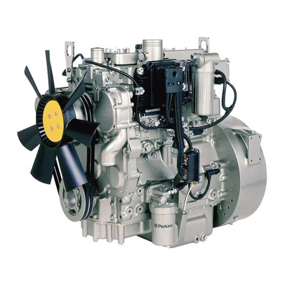
SEBU8119-04 Product Information Section Model Views Model Views i02786384 Model View Illustrations The following model views show typical features of the engine. Due to individual applications, your engine may appear different from the illustrations. Note: Only major components are identified on the following illustrations. - Page 22 SEBU8119-04 Product Information Section Engine Description Illustration 19 g01391893 Rear right engine view (16) Oil gauge (21) Exhaust manifold (26) Oil pan (17) Air intake (22) Exhaust elbow (27) Drain plug (oil) (18) Oil filler (23) Turbocharger (28) Drain plug or coolant sampling valve (19) Front lifting eye (24) Wastegate solenoid (29) Breather...
- Page 23 SEBU8119-04 Product Information Section Engine Description • Torque rise shaping • Injection timing control • System diagnostics For more information on electronic engine features, refer to the Operation and Maintenance Manual, “Features and Controls” topic (Operation Section). Engine Diagnostics The engine has built-in diagnostics in order to ensure that the engine systems are functioning correctly.
-
Page 24: Product Identification Information
Make a copy of this list for a record. Keep the information for future reference. Illustration 21 g01331472 Location of the serial number plate Record for Reference Perkins engines are identified by an engine serial Engine Model number. Engine Serial number An example of an engine number is PJ*****U000001J. - Page 25 SEBU8119-04 Product Information Section Emissions Certification Film Alternator Belt i02894856 Emissions Certification Film Label for compliant engines Typical examples of emissions labels Illustration 23 g01440937...
-
Page 26: Operation Section
If alterations are made, ensure that correct lifting devices are provided. Consult your Perkins dealer or your Perkins distributor for information regarding fixtures for correct engine lifting. Illustration 24... - Page 27 Rust can form on the cylinder walls. Rust on the cylinder walls will cause increased engine wear and a reduction in engine service life. Perkins are not responsible for damage which may occur when an engine is in storage after a period in service.
- Page 28 SEBU8119-04 Operation Section Engine Storage 1. Completely clean the outside of the engine. Fill the oil pan to the Full Mark on the engine oil level gauge with new, clean lubricating oil. Add 2. Ensure that the vehicle is on level ground. 1762811 POWERPART Lay-Up 2 to the oil in 3.
-
Page 29: Gauges And Indicators
Determine and correct the cause of any significant 1. Reduce the load and the engine rpm. change in the readings. Consult your Perkins dealer or your Perkins distributor for assistance. 2. Determine if the engine must be shut down... -
Page 30: Features And Controls
SEBU8119-04 Operation Section Features and Controls Features and Controls i02296746 Monitoring System Table 2 Shutdown Warning Lamp Lamp Status Description of lamp status Engine Status Lamp Lamp check When the engine start switch is turned to the “ON” posi- The engine has not been tion both lamps will illuminate for 2 seconds only. - Page 31 For each of the programmed modes, refer to Troubleshooting , “Indicator Lamps” for more information on Indicator Lamps. For more information or assistance for repairs, consult your Perkins dealer or your Perkins distributor. i02788240 Sensors and Electrical Components...
- Page 32 SEBU8119-04 Operation Section Sensors and Electrical Components Illustration 27 g01392818 (1) Coolant temperature sensor (4) Fuel pressure sensor (7) Primary position sensor (2) Intake manifold air temperature sensor (5) Electronic control module (ECM) (8) Secondary position sensor (3) Intake manifold pressure sensor (6) Oil pressure sensor...
- Page 33 SEBU8119-04 Operation Section Sensors and Electrical Components Illustration 28 g01330220 (1) Coolant temperature sensor (3) Intake manifold pressure sensor (5) Electronic control module (ECM) (2) Intake manifold air temperature sensor (4) Fuel pressure sensor...
- Page 34 SEBU8119-04 Operation Section Sensors and Electrical Components Illustration 29 g01330325 (6) Engine oil pressure sensor (7) Primary speed/timing sensor (8) Secondary speed/timing sensor Illustration 28 and illustration 29 shows the sensors • Intake manifold Air Temperature Sensor and the ECM in position on the engine. •...
- Page 35 SEBU8119-04 Operation Section Sensors and Electrical Components Failure of the Coolant Temperature Low Oil Pressure Warning Sensor The setpoint for the low pressure warning is dependent upon the engine speed. The fault will be The ECM (5) will detect a failure of the coolant active and logged only if the engine has been running temperature sensor.
- Page 36 SEBU8119-04 Operation Section Engine Shutoffs and Engine Alarms In order to check the correct operation of the sensor, The alarm is operated by a sensor or by a switch. refer to Troubleshooting, “Engine speed/Timing When the sensor or the switch is activated a signal is sensor - Test”.
- Page 37 SEBU8119-04 Operation Section Overspeed If corrective measures are not taken within a reasonable time, engine damage could result. The alarm will continue until the condition is corrected. The alarm may need to be reset. Testing Turning the keyswitch to the ON position will check the indicator lights on the control panel.
-
Page 38: Engine Diagnostics
Retrieval Self-Diagnostics “ “ Diagnostic” ” Lamp Perkins electronic engines have the capability to perform a self-diagnostics test. When the system Use the “DIAGNOSTIC” lamp or an electronic service detects an active problem, a diagnostic lamp is tool to determine the diagnostic flash code. - Page 39 SEBU8119-04 Operation Section Diagnostic Flash Code Retrieval Table 3 Flash Codes for 1106D Industrial Engine Diagnostic Effect On Engine Performance Suggested Operator Action Flash Code Description Engine Low Power Reduced Engine Service Schedule a Misfire Engine Shutdown Service. Speed No. 1 Injector Fault No.
- Page 40 SEBU8119-04 Operation Section Fault Logging (Table 3, contd) Machine Security System Module Fault Ignition Key Switch Fault ECM Power Supply Voltage Fault SAE J1939 Data Link Fault 5 Volt Sensor DC Power Supply Fault 8 Volt Sensor DC Power Supply Fault Customer/System Parmeter Fault If warning lamps are installed refer to this table.
- Page 41 SEBU8119-04 Operation Section Engine Operation with Intermittent Diagnostic Codes This information can be useful to help troubleshoot the situation. The information can also be used for future reference. For more information on diagnostic codes, refer to the Troubleshooting Guide for this engine.
-
Page 42: Engine Starting
SEBU8119-04 Operation Section Engine Starting Engine Starting Starting the Engine 1. Disengage any equipment that is driven by the i02322201 engine. Before Starting Engine 2. Turn the keyswitch to the RUN position. Leave the keyswitch in the RUN position until the warning light for the glow plugs is extinguished. - Page 43 SEBU8119-04 Operation Section After Starting Engine Do not check the high pressure fuel lines with the NOTICE engine or the starting motor in operation. If you Using a battery source with the same voltage as the inspect the engine in operation, always use the electric starting motor.
-
Page 44: Engine Operation
Fuel Conservation Practices The efficiency of the engine can affect the fuel economy. Perkins design and technology in manufacturing provides maximum fuel efficiency in all applications. Follow the recommended procedures in order to attain optimum performance for the life of the engine. -
Page 45: Engine Stopping
SEBU8119-04 Operation Section Engine Stopping Engine Stopping i02330274 After Stopping Engine i06832774 Stopping the Engine Note: Before you check the engine oil, do not operate the engine for at least 10 minutes in order to allow the engine oil to return to the oil pan. NOTICE Stopping the engine immediately after it has been working under load, can result in overheating and ac-... - Page 46 SEBU8119-04 Operation Section After Stopping Engine • Check the coolant for correct antifreeze protection and the correct corrosion protection. Add the correct coolant/water mixture, if necessary. • Perform all required periodic maintenance on all driven equipment. This maintenance is outlined in the instructions from the OEM.
-
Page 47: Cold Weather Operation
Cold Weather Operation • Install the correct specification of engine lubricant before the beginning of cold weather. Perkins Diesel Engines can operate effectively in • Check all rubber parts (hoses, fan drive belts.) cold weather. During cold weather, the starting and weekly. - Page 48 An electric block heater can be activated once the • Pushrods may become bent. engine is stopped. An effective block heater is typically a 1250/1500 W unit. Consult your Perkins • Other damage to valve train components can dealer or your Perkins distributor for more result.
- Page 49 This CFPP gives an estimate of the lower operability temperature of fuel Note: Perkins discourages the use of all air flow restriction devices such as radiator shutters. Be aware of these properties when diesel fuel is Restriction of the air flow can result in the following: purchased.
- Page 50 SEBU8119-04 Operation Section Fuel Related Components in Cold Weather i02323237 Fuel Related Components in Cold Weather Fuel Tanks Condensation can form in partially filled fuel tanks. Top off the fuel tanks after you operate the engine. Fuel tanks should contain some provision for draining water and sediment from the bottom of the tanks.
-
Page 51: Maintenance Section
Refer to the OEM specifications for the capacity of the American Petroleum Institute (API) is recognized the auxiliary oil filter. by Perkins. For detailed information about this system, see the latest edition of the “API publication Cooling System No. - Page 52 SEBU8119-04 Maintenance Section Fluid Recommendations Terminology used in Perkins engines when the following oils are recommended: API CH-4 and API CG-4. DHD-1 oils are intended to provide superior performance in Certain abbreviations follow the nomenclature of comparison to API CG-4.
- Page 53 API CH-4 oils are recommended for the cylinder bore. conditions that demand a premium oil. Your Perkins distributor has specific guidelines for optimizing oil NOTICE change intervals.
- Page 54 Aftermarket Oil Additives Synthetic base oils generally perform better than Perkins does not recommend the use of aftermarket conventional oils in the following two areas: additives in oil. It is not necessary to use aftermarket additives in order to achieve the engine's maximum •...
- Page 55 9 . of the oil according to the specification during the entire oil change interval. NOTICE The footnotes are a key part of the Perkins Specifica- i02788820 tion for Distillate Diesel Fuel Table. Read ALL of the footnotes. Fluid Recommendations (Fuel Specification) •...
- Page 56 Regional regulations, national regulations or international regulations can require a fuel with a specific sulfur limit. Consult all applicable regu- lations before selecting a fuel for a given engine application. Perkins fuel systems and engine components can operate on high sulfur fuels.
- Page 57 The viscosity of the fuel is significant because fuel NOTICE serves as a lubricant for the fuel system components. Operating with fuels that do not meet the Perkins rec- Fuel must have sufficient viscosity in order to ommendations can cause the following effects: Start-...
- Page 58 SEBU8119-04 Maintenance Section Fuel Specification Distillation By using the test methods “ASTM D5453, ASTM D2622, or ISO 20846 ISO 20884”, the content of sulfur in low sulfur diesel (LSD) fuel must be below This is an indication of the mixture of different hydrocarbons in the fuel.
- Page 59 Protection Agency (EPA) and European Certification performed on a HFRR, operated at 60 °C (140 °F). fuels. Perkins does not certify engines on any other Refer to “ISO 12156-1 ”. Fuels must have minimum fuel. The user of the engine has the responsibility of viscosity of 1.4 centistokes that is delivered to the...
- Page 60 SEBU8119-04 Maintenance Section Fuel Specification • The oil change interval can be affected by the use • Biodiesel is an excellent medium for microbial of biodiesel. Use Services Oil Analysis in order to contamination and growth. Microbial monitor the condition of the engine oil. Use contamination and growth can cause corrosion in Services Oil Analysis also in order to determine the fuel system and premature plugging of the fuel...
- Page 61 These failures can be avoided with correct cooling Perkins recognizes the fact that additives may be system maintenance. Cooling system maintenance is required in some special circumstances. Fuel as important as maintenance of the fuel system and additives need to be used with caution.
- Page 62 • Plugging of radiators, coolers, and small passages • ASTM American Society for Testing and Materials Glycol The following two coolants are used in Perkins diesel engines: Glycol in the coolant helps to provide protection against the following conditions: Preferred – Perkins ELC •...
- Page 63 Perkins provides ELC for use in the following Do not use standard supplemental coolant additive applications: (SCA). • Heavy-duty spark ignited gas engines When using Perkins ELC, do not use standard SCA's or SCA filters. • Heavy-duty diesel engines • Automotive applications ELC Cooling System Cleaning The anti-corrosion package for ELC is different from the anti-corrosion package for other coolants.
- Page 64 Then, fill the cooling system with premixed ELC. 4. Use Perkins cleaner to clean the system. Follow This should lower the contamination to less than the instruction on the label. 10 percent.
- Page 65 Use the equation that is in Table 17 to determine the Multiplication Total Volume of the Amount of SCA amount of Perkins SCA that is required when the Cooling System (V) Factor that is Required (X) cooling system is initially filled.
-
Page 66: Maintenance Interval Schedule
SEBU8119-04 Maintenance Section Maintenance Interval Schedule “ Hoses and Clamps - Inspect/Replace” ..96 i02666635 Maintenance Interval Schedule Every 50 Service Hours or Weekly “ Fuel Tank Water and Sediment - Drain” ..96 When Required Every 250 Service Hours “... -
Page 67: Maintenance Interval Schedule
SEBU8119-04 Maintenance Section Maintenance Interval Schedule “ Turbocharger - Inspect” ..... . Every 3000 Service Hours “ Alternator and Fan Belts - Replace” ..69 Every 3000 Service Hours or 2 Years “... -
Page 68: Aftercooler Core - Inspect
SEBU8119-04 Maintenance Section Aftercooler Core - Clean/Test i02322260 Aftercooler Core - Clean/Test Personal injury can result from air pressure. Personal injury can result without following prop- er procedure. When using pressure air, wear a 1. Remove the core. Refer to the OEM information for protective face shield and protective clothing. -
Page 69: Battery - Replace
Make repairs, if necessary. i02322311 Alternator - Inspect Perkins recommends a scheduled inspection of the alternator. Inspect the alternator for loose connections and correct battery charging. Check the ammeter (if equipped) during engine operation in order to ensure correct battery performance and/or correct performance of the electrical system. -
Page 70: Battery Or Battery Cable - Disconnect
SEBU8119-04 Maintenance Section Battery Electrolyte Level - Check The battery cables or the batteries should not be All lead-acid batteries contain sulfuric acid which can burn the skin and clothing. Always wear a removed with the battery cover in place. The bat- face shield and protective clothing when working tery cover should be removed before any servic- on or near batteries. -
Page 71: Belt Tensioner - Inspect
SEBU8119-04 Maintenance Section Belt Tensioner - Inspect 4. Clean all disconnected connection and battery Ensure that the belt tensioner is securely installed. Visually inspect the belt tensioner (1) for damage. terminals. Check that the roller on the tensioner rotates freely. 5. - Page 72 Maintenance Section Cooling System Coolant (Commercial Heavy-Duty) - Change Drain For information regarding the disposal and the recycling of used coolant, consult your Perkins dealer or your Perkins distributor. Flush Pressurized System: Hot coolant can cause seri- ous burns. To open the cooling system filler cap, stop the engine and wait until the cooling system 1.
- Page 73 SEBU8119-04 Maintenance Section Cooling System Coolant (ELC) - Change 3. Start and run the engine at low idle. Increase the NOTICE engine rpm to high idle. Run the engine at high Keep all parts clean from contaminants. idle for one minute in order to purge the air from Contaminants may cause rapid wear and shortened the cavities of the engine block.
- Page 74 Decrease the engine speed to low idle. Stop the engine. For information regarding the disposal and the recycling of used coolant, consult your Perkins dealer 4. Check the coolant level. Maintain the coolant level or your Perkins distributor.
-
Page 75: Cooling System Coolant Level - Check
Tank Note: The cooling system may not have been Illustration 38 g02590196 provided by Perkins. The procedure that follows is for Filler cap typical cooling systems. Refer to the OEM information for the correct procedures. 4. Clean filler cap and the receptacle. Reinstall the Check the coolant level when the engine is stopped filler cap and inspect the cooling system for leaks. - Page 76 SEBU8119-04 Maintenance Section Cooling System Supplemental Coolant Additive (SCA) - Test/Add 4. Inspect the cooling system for leaks. i03644948 Cooling System Supplemental Coolant Additive (SCA) - Test/ Cooling system coolant additive contains alkali. To help prevent personal injury, avoid contact Illustration 39 g00285520 with the skin and the eyes.
-
Page 77: Driven Equipment - Check
SEBU8119-04 Maintenance Section Crankcase Breather (Canister) - Replace NOTICE When any servicing or repair of the engine cooling system is performed the procedure must be per- formed with the engine on level ground. This will al- low you to accurately check the coolant level. This will also help in avoiding the risk of introducing an air lock into the coolant system. -
Page 78: Engine - Clean
Note: The air filter system may not have been NOTICE provided by Perkins. The procedure that follows is for Failure to protect some engine components from a typical air filter system. Refer to the OEM washing may make your engine warranty invalid. Al- information for the correct procedure. - Page 79 SEBU8119-04 Maintenance Section Engine Air Cleaner Element (Dual Element) - Clean/Replace The primary air cleaner element can be used up to 7. Reset the air cleaner service indicator. six times if the element is properly cleaned and properly inspected. The primary air cleaner element Cleaning the Primary Air Cleaner should be replaced at least one time per year.
-
Page 80: Inspect/Replace
SEBU8119-04 Maintenance Section Engine Air Cleaner Element (Single Element) - Inspect/Replace Pressurized Air Note: Refer to “Inspecting the Primary Air Cleaner Elements”. Inspecting the Primary Air Cleaner Elements Personal injury can result from air pressure. Personal injury can result without following prop- er procedure. -
Page 81: Engine Air Cleaner Service Indicator - Inspect
SEBU8119-04 Maintenance Section Engine Air Cleaner Service Indicator - Inspect • Check for ease of resetting. The service indicator NOTICE should reset in less than three pushes. Never service the air cleaner element with the engine running since this will allow dirt to enter the engine. •... -
Page 82: Engine Oil Sample - Obtain
Refer to the OEM information for the recommended torques. Note: Ensure that the engine is either level or that When the engine mounts are supplied by Perkins the the engine is in the normal operating position in order maintenance procedure will be supplied in the to obtain a true level indication. -
Page 83: Engine Oil And Filter - Change
SEBU8119-04 Maintenance Section Engine Oil and Filter - Change Perkins recommends using a sampling valve in order The sample can be checked for the following: the to obtain oil samples. The quality and the consistency quality of the oil, the existence of any coolant in the... - Page 84 Perkins oil filters are manufactured to Perkins specifi- cations. Use of an oil filter that is not recommended by Perkins could result in severe damage to the en- 3. Clean sealing surface (2). gine bearings, crankshaft, etc., as a result of the larg- er waste particles from unfiltered oil entering the 4.
-
Page 85: Engine Oil And Filter - Change
Under filling or over filling the crankcase with oil can cause engine damage. This maintenance is recommended by Perkins as part of a lubrication and preventive maintenance schedule in order to help provide maximum engine 2. Start the engine and run the engine at “LOW IDLE”... -
Page 86: Fan Clearance - Check
NOTICE Only qualified service personel should perform this maintenance. Refer to the Service Manual or your au- thorized Perkins dealer or your Perkins distributor for the complete valve lash adjustment procedure. Operation of Perkins engines with incorrect valve lash can reduce engine efficiency, and also reduce engine component life. -
Page 87: Fuel System - Prime
SEBU8119-04 Maintenance Section Fuel System - Prime Illustration 52 g01348394 Adjustment of the cover will change the clearance Note: Refer to Testing and Adjusting Manual , (gap) between the edge of the cover and the tip of “Cleanliness of Fuel System Components” for the fan blade. - Page 88 SEBU8119-04 Maintenance Section Fuel System - Prime • A leak exists in the low pressure fuel system. • The fuel filter has been replaced. Contact with high pressure fuel may cause fluid penetration and burn hazards. High pressure fuel Hand Fuel Priming Pump spray may cause a fire hazard.
-
Page 89: Fuel System Primary Filter/Water Separator - Drain
SEBU8119-04 Maintenance Section Fuel System Primary Filter/Water Separator - Drain Contact with high pressure fuel may cause fluid penetration and burn hazards. High pressure fuel spray may cause a fire hazard. Failure to follow these inspection, maintenance and service in- structions may cause personal injury or death. -
Page 90: Fuel System Primary Filter (Water Separator) Element - Replace
SEBU8119-04 Maintenance Section Fuel System Primary Filter (Water Separator) Element - Replace 1. Install a suitable tube onto drain (1). Loosen vent screw (2). 2. Open drain (1). Allow the fluid to drain into the container. 3. Tighten drain (1) by hand pressure only. Remove the tube and dispose of the drained fluid in a safe place. - Page 91 SEBU8119-04 Maintenance Section Fuel System Primary Filter (Water Separator) Element - Replace 14. The secondary filter must be replaced at the same time as the primary filter. Refer to the Operation and Maintenance Manual , “Fuel System Filter - Replace”. Type Two Filter Fuel leaked or spilled onto hot surfaces or electri- cal components can cause a fire.
- Page 92 SEBU8119-04 Maintenance Section Fuel System Primary Filter (Water Separator) Element - Replace Illustration 58 g01370515 Illustration 59 g01370722 Typical example Typical example 3. Install a suitable tube onto the drain (1). Open the 6. Rotate the bowl (3) counterclockwise in order to drain (1).
- Page 93 SEBU8119-04 Maintenance Section Fuel System Primary Filter (Water Separator) Element - Replace Illustration 60 g01370724 Illustration 61 g01371107 Typical example Typical example 7. Use a suitable tool in order to remove the old 8. Lubricate the O ring seal (5 ) with clean engine oil canister (4).
-
Page 94: Fuel System Secondary Filter - Replace
SEBU8119-04 Maintenance Section Fuel System Secondary Filter - Replace 13. The secondary filter must be replaced at the After the engine has stopped, you must wait for 60 seconds in order to allow the fuel pressure to be same time as the primary filter. Refer to the purged from the high pressure fuel lines before any Operation and Maintenance Manual , “Fuel service or repair is performed on the engine fuel... - Page 95 SEBU8119-04 Maintenance Section Fuel System Secondary Filter - Replace 7. Prime the fuel system. Refer to the Operation and After the engine has stopped, you must wait for 60 seconds in order to allow the fuel pressure to be Maintenance Manual, “Fuel System - Prime” for purged from the high pressure fuel lines before any more information.
-
Page 96: Hoses And Clamps - Inspect/Replace
SEBU8119-04 Maintenance Section Fuel Tank Water and Sediment - Drain 7. Prime the fuel system. Refer to the Operation and Some fuel tanks use supply pipes that allow water and sediment to settle below the end of the fuel Maintenance Manual, “Fuel System - Prime” for supply pipe. -
Page 97: Radiator - Clean
Radiator - Clean • Anticipated expansion and contraction of the hose • Anticipated expansion and contraction of the The radiator is not usually supplied by Perkins. The fittings following text describes a typical cleaning procedure for the radiator. Refer to the OEM information for Replace the Hoses and the Clamps further information on cleaning the radiator. -
Page 98: Severe Service Application - Check
• Extending the maintenance intervals • The temperature of the fluid in the engine Refer to the standards for the engine or consult your Perkins dealer or your Perkins distributor in order to determine if the engine is operating within the defined parameters. -
Page 99: Starting Motor - Inspect
Adjusting Manual, “Electric Starting System - or removed for the cleaning of the compressor. Test” for more information on the checking procedure and for specifications consult your Perkins dealer or your Perkins distributor for assistance. 1. Remove the pipe from the turbocharger exhaust outlet and remove the air intake pipe to the turbocharger. -
Page 100: Walk-Around Inspection
Remove the water pump. Refer to Disassembly and Assembly , “Water Pump - Remove and Install”. For more information, consult your Perkins dealer or your Perkins distributor. • Inspect the lubrication system for leaks at the front Illustration 66... -
Page 101: Water Pump - Inspect
SEBU8119-04 Maintenance Section Water Pump - Inspect Belts for multiple groove pulleys must be replaced as • Check the condition of the gauges. Replace any matched sets. If only one belt is replaced, the belt will gauges that are cracked. Replace any gauge that carry more load than the belts that are not replaced. -
Page 102: Warranty Section
This engine may be covered by an Emissions Warranty. Consult your authorized Perkins dealer or distributor to determine if your engine is emissions certified and if your engine is subject to an Emissions... -
Page 103: Index
SEBU8119-04 Index Section Index Crushing Prevention and Cutting Prevention.. 14 After Starting Engine ........43 After Stopping Engine ........45 Aftercooler Core - Clean/Test......68 Diagnostic Flash Code Retrieval..... 38 Aftercooler Core - Inspect ....... 68 “Diagnostic” Lamp ........38 Alternator - Inspect .......... - Page 104 SEBU8119-04 Index Section Engine Operation ..........44 Fuel System Primary Filter (Water Separator) Engine Operation with Active Diagnostic Element - Replace ......... 90 Codes ............40 Type One Filter ..........90 Engine Operation with Intermittent Type Two Filter ..........91 Diagnostic Codes ..........
- Page 105 SEBU8119-04 Index Section Every 500 Service Hours ......66 Secondary Speed/Timing Sensor 8..... 36 Every 500 Service Hours or 1 Year ..... 66 Sensor Locations ......... 31 Every Week ..........66 Severe Service Application - Check....98 Initial 500 Service Hours......66 Environmental Factors.........
- Page 107 Product and Dealer Information Note: For product identification plate locations, see the section “Product Identification Information” in the Operation and Maintenance Manual. Delivery Date: Product Information Model: Product Identification Number: Engine Serial Number: Transmission Serial Number: Generator Serial Number: Attachment Serial Numbers: Attachment Information: Customer Equipment Number: Dealer Equipment Number:...
- Page 108 SEBU8119 ©2021 Perkins Engines Company Limited All Rights Reserved January 2021...
Need help?
Do you have a question about the 1106D and is the answer not in the manual?
Questions and answers