Table of Contents
Advertisement
Quick Links
Operation & Maintenance Manual
This manual contains important safety information.
Do not destroy this manual.
This manual must be available to the personnel who operate and maintain this machine.
Doosan purchased Bobcat Company from Ingersoll-Rand Company in
2007. Any reference to Ingersoll-Rand Company or use of trademarks,
service marks, logos, or other proprietary identifying marks belonging
to Ingersoll-Rand Company in this manual is historical or nominative
in nature, and is not meant to suggest a current affiliation between
Ingersoll-Rand Company and Doosan Company or the products of
either.
Utility Equipment
P.O. Box 868 - 501 Sanford Ave
Mocksville, N.C. 27028
Book 22846430 (8-21-06) Rev. A
Revised (10-12)
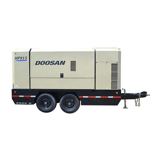
HP915WCU
XP1000WCU
CODE: B
MHP825WCU
CODE: C
Advertisement
Table of Contents

Related Manuals for Ingersoll-Rand HP915WCU


Summary of Contents for Ingersoll-Rand HP915WCU
- Page 1 This manual must be available to the personnel who operate and maintain this machine. Doosan purchased Bobcat Company from Ingersoll-Rand Company in 2007. Any reference to Ingersoll-Rand Company or use of trademarks, service marks, logos, or other proprietary identifying marks belonging...
- Page 2 CALIFORNIA Proposition 65 Warning Diesel engine exhaust and some of its constituents are known to the State of California to cause cancer, birth defects, and other reproductive harm.
-
Page 3: Table Of Contents
TABLE OF CONTENTS Operation & Maintenance Manual TITLE PAGE FOREWORD ............7 SAFETY . - Page 4 TABLE OF CONTENTS Operation & Maintenance Manual TITLE PAGE OPERATING INSTRUCTIONS ..........33 Operating Instructions .
- Page 5 TABLE OF CONTENTS Operation & Maintenance Manual TITLE PAGE Reassembly ..............65 Ventilation .
- Page 6 TABLE OF CONTENTS Operation & Maintenance Manual TITLE PAGE...
-
Page 7: Foreword
Foreword Book: 22846430 (8-21-06) Rev. A... - Page 8 Details of approved equipment are available from Ingersoll-Rand Service departments. The use of repair parts other than those included within the Ingersoll-Rand approved parts list may create hazardous conditions over which Ingersoll-Rand has no control. Therefore, Ingersoll- Rand cannot be held responsible for equipment in which non-approved repair parts are installed.
- Page 9 Your Ingersoll-Rand dealer will assist with setup and initial startup of the compressor. He will also provide brief operating and service instructions and will insure that a copy of this manual is included with the machine.
- Page 10 **Always use Ingersoll-Rand Replacement parts!** Book: 22846430 (8-21-06) Rev. A...
-
Page 11: Safety
Safety Book: 22846430 (8-21-06) Rev. A... -
Page 12: Safety Precautions
Operating & Maintenance Manual Safety Safety Safety Precautions General Information Never operate unit without first observing all safety warnings and carefully reading the operation and maintenance manual shipped from the factory with this machine. Ensure that the operator reads and understands the decals and consults the manuals before maintenance or operation. -
Page 13: Compressed Air
Safety Operating & Maintenance Manual Never operate unit with guards, covers or screens removed. Keep hands, hair, clothing, tools, blow gun tips, etc. well away from moving parts. Compressed Air Compressed air can be dangerous if incorrectly handled. Before doing any work on the unit, ensure that all pressure is vented from the system and that the machine cannot be started accidentally. -
Page 14: Materials
Operating & Maintenance Manual Safety Materials The following substances may be produced during the operation of this machine: • brake lining dust • engine exhaust fumes WARNING Avoid inhalation Ensure that adequate ventilation of the cooling system and exhaust gases is maintained at all times. -
Page 15: Battery
Safety Operating & Maintenance Manual This machine may include such materials as oil, diesel fuel, antifreeze, brake fluid, oil/air filters and batteries which may require proper disposal when performing maintenance and service tasks. Contact local authorities for proper disposal of these materials. Battery A battery contains sulfuric acid and can give off gases which are corrosive and potentially explosive. -
Page 16: Transport
Operating & Maintenance Manual Safety Transport When loading or transporting machines ensure that the specified lifting and tie down points are used. When loading or transporting machines ensure that the towing vehicle, its size, weight, towing hitch and electrical supply are all suitable to provide safe and stable towing at speeds either, up to the legal maximum for the country in which it is being towed or, as specified for the machine model if lower than the legal maximum. -
Page 17: Decals
Safety Operating & Maintenance Manual Decals Decals are located on the machine to point out potential safety hazards. Read and follow these instructions. If you do not understand the instructions, inform your supervisor. Note that there are different decal headings: DANGER (Red Background) Indicates the presence of a hazard which WILL cause serious injury,... - Page 18 Operating & Maintenance Manual Safety FREE SAFETY DECALS To promote communication of Safety Warnings on products manufactured by the Portable Compressor Division in Mocksville, N.C. Safety Decals are available free of charge. Safety decals are identified by the decal heading: DANGER, WARNING or CAUTION. Decal part numbers are on the bottom of each decal and are also listed in the compressor’s parts manual.
-
Page 19: Noise Emission
Noise Emission Book: 22846430 (8-21-06) Rev. A... -
Page 20: Noise Emission Control Maintenance Log
Operating & Maintenance Manual Noise Emission Noise Emission Control Maintenance Log COMPRESSOR MODEL_________________________ SERIAL NO. __________________________________ USER UNIT NO. _______________________________ UNIT IDENTIFICATION DEALER OR DISTRIBUTOR FROM WHOM PURCHASED: Engine Make & Model:_________________ Serial No.:__________________________ __________________________________ Purchaser or Owner:__________________ __________________________________ Address: ___________________________ Date Purchased:_____________________ __________________________________ The Noise Control Act of 1972 (86 Stat. -
Page 21: Introduction
Noise Emission Operating & Maintenance Manual Introduction The unit for which this Maintenance Log is provided conforms to U.S. E.P.A. Regulations for Noise Emissions, applicable to Portable Air Compressors. The purpose of this book is to provide (1) the Maintenance Performance Schedule for all required noise emission controls and (2) space so that the purchaser or owner can record what maintenance was done, by whom, where and when. -
Page 22: Fasteners
Inspect and maintain engine condition and operation as recommended in the manuals supplied by the engine manufacturer. J. Fuels and Lubricants Use only the types and grades of fuels and lubricants recommended in the Ingersoll-Rand Company and Engine Manufacturer’s Operator and Maintenance Manuals. PCD685... - Page 23 Noise Emission Operating & Maintenance Manual Table 1: MAINTENANCE RECORD FOR NOISE EMISSION CONTROL AND EXTENDED WARRANTY ITEM NO. DESCRIPTION OF WORK OR HOURMETER MAINT/ LOCATION WORK DONE COMMENTS READING INSPECT DATE CITY/STATE BY (NAME) PCD685 Book: 22846430 (8-21-06) Rev. A...
- Page 24 **Always use Ingersoll-Rand Replacement parts!**...
-
Page 25: General Information
General Information Book: 22846430 (8-21-06) Rev. A... -
Page 26: General Information - Msa (Srg/Hrg)
Operating & Maintenance Manual General Information General Information - MSA (SRG/HRG) Book: 22846430 (8-21-06) Rev. A... - Page 27 General Information Operating & Maintenance Manual Book: 22846430 (8-21-06) Rev. A...
- Page 28 Operating & Maintenance Manual General Information MODEL MHP825 XP1000 HP915 COMPRESSOR 1000 Actual free air delivery. (28.3) (25.0)(28. (23,3) /min) Normal operating discharge pressure. (bar) (12) (10) Safety valve setting (bar) (15) (15) (15) °F 14/120 14/120 14/120 Whisperized (W) operating ambient temperature range (°C) (-10/+49) (-10/+49)
-
Page 29: Sound Level Data ('W' Model)
High Speed Running Gear (HSRG) Number of Wheels Tire size. 8-14.5 LT/G Tire pressure. 110 psi (7.6 bar) Maximum towing speed 65 mph (105kph) Further information may be obtained by request through Ingersoll-Rand customer services department. Book: 22846430 (8-21-06) Rev. A... - Page 30 **Always use Ingersoll-Rand Replacement parts!**...
-
Page 31: Operating Instructions
Operating Instructions Book: 22846430 (8-21-06) Rev. A... -
Page 32: Commissioning
Operating & Maintenance Manual Operating Instructions Operating Instructions Commissioning Upon receipt of the unit, and prior to putting it into service, it is important to adhere strictly to the instructions given below in PRIOR TO STARTING. Ensure that the operator reads and understands the decals and consults the manuals before maintenance or operation. - Page 33 Operating Instructions Operating & Maintenance Manual WARNING If more than one compressor is connected to one common downstream plant, effective check valves and isolation valves must be fitted and controlled by work procedures, so that one machine cannot accidently be pressurised/over pressurised by another.
-
Page 34: Prior To Starting
Operating & Maintenance Manual Operating Instructions Prior to Starting 1. Place the unit in a position that is as level as possible. The design of the unit permits a 15 degree lengthways and sideways limit on out of level operation. When the unit has to be operated out of level, it is important to keep the engine oil level near the high level mark (with the unit level). - Page 35 Operating Instructions Operating & Maintenance Manual CAUTION 8. Do not operate the machine with the canopy/doors in the open position as this may cause overheating and operators to be exposed to high noise levels. 9. Check the emergency stop. Rotate knob as indicated to release. 10.
-
Page 36: Operating Controls And Instruments
Operating & Maintenance Manual Operating Instructions Operating Controls and Instruments The operating controls and instruments are arranged on the control panel as shown above. A description of each panel device is as follows: 1. Panel Light: Illuminates the instrument control panel controlled by Switch 14. 2. - Page 37 Operating Instructions Operating & Maintenance Manual 20. Discharge Air Pressure Gage: Indicates pressure in receiver tank, normally from 0 psi(kPa) to the rated pressure of the machine. 21. Engine Tachometer: Indicates engine speed in RPM from 0 when stopped to full speed.
- Page 38 Operating & Maintenance Manual Operating Instructions Wedge Diagnostic Display Codes 1. High Compressor Temp: Fault indicator lamp. Indicates shutdown due to high compressor temperature. 2. Low Engine Oil Pressure: Fault indicator lamp. Indicates shutdown due to low engine oil pressure. 3.
- Page 39 Operating Instructions Operating & Maintenance Manual 7. Restricted Air Filter: Alarm indicator lamp. Indicates engine/compressor air inlet filters need service. 8. Restricted IQ Air Filters: Fault indicator lamp. Indicates shutdown due to high pressure in “IQ” air filters (if equipped). 9.
-
Page 40: Wedge Diagnostic Display Codes
Operating & Maintenance Manual Operating Instructions WEDGE DIAGNOSTIC DISPLAY CODES ALERT SHUTDOWN Condition Code Light (Blinks) Code Light (Steady) Delay (Sec) Engine Speed < Min. CPRSR Malf Engine Speed > Max. CPRSR Malf Engine Crank Time CPRSR Malf Exceeded High Engine Oil Temp CPRSR Malf High Intake Manifold CPRSR Malf... - Page 41 Operating Instructions Operating & Maintenance Manual ALERT SHUTDOWN Condition Code Light (Blinks) Code Light (Steady) Delay (Sec) Safety Valve Open CPRSR Malf Sep. Tank Temp > 247 CPRSR Malf deg F Machine ID Not Valid CPRSR Malf Sep. Tank Temp (RT1) CPRSR Malf Sensor Fault Reg.
-
Page 42: Cummins Engine Model Qsc8.3 & Qsl-9
Operating & Maintenance Manual Operating Instructions Cummins Engine Model QSC8.3 & QSL-9 Displayed Code Definition Engine Control Module - Critical internal failure Engine Speed/Position Sensor Circuit - lost both of two signals Intake Manifold Pressure Circuit - voltage above normal or shorted high Intake Manifold Pressure Sensor Circuit - voltage below normal or shorted low Engine Oil Pressure Sensor Circuit - voltage above normal or shorted high Engine Oil Pressure Sensor Circuit - voltage below normal or shorted low... - Page 43 Operating Instructions Operating & Maintenance Manual Displayed Code Definition Engine Coolant Pressure Sensor Circuit - Voltage below normal or shorted low Engine Coolatn pressure Low - Warning Engine Speed High - Critical Engine Coolant Level Low - Critical Sensor Supply Voltage # 3 Circuit - Voltage below normal or shorted low Ambient Air Temperature Sensor Circuit - Voltage above normal or shorted high Ambient Air Temperature Sensor Circuit - Voltage below normal or shorted low Engine Fuel Temperature High - Warning...
- Page 44 Operating & Maintenance Manual Operating Instructions Displayed Code Definition Engine Oil Pressure Low - Critical Water In Fuel Indicator High - Maintenance Engine Coolant Level - Data Incorrect Engine Oil Temperature - Data Incorrect Water in Fuel Sensor Circuit - Voltage above normal or shorted high Water in Fuel Sensor Circuit - Voltage below normal or shorted low Intake Manifold Pressure Sensor Circuit - Data Incorrect Engine Oil Pressure Sensor Circuit - Data Incorrect...
- Page 45 Operating Instructions Operating & Maintenance Manual Displayed Code Definition Engine Speed/Position #2 Mechanical Misalignment - Mechanical system malfunction Engine Speed/Position #2 Camshaft SYNC Error - Data Incorrect Engine Speed Sensor (Camshaft) - Data Incorrect Cylinder Power Imbalance between cylinders - Data Incorrect 1139 Injector Cylinder #1 - Mechanical System Malfunction 1141...
- Page 46 Operating & Maintenance Manual Operating Instructions Displayed Code Definition 2555 Intake Air Heater #1 Circuit - Voltage above normal or shorted high 2556 Intake Air Heater #1 Circuit - Voltage below normal or shorted low 2963 Engine Coolant Temeprature High - Alert 2964 Intake Manifold Air Temeprature - Alert 2973...
-
Page 47: Starting The Machine
Operating Instructions Operating & Maintenance Manual Starting the Machine Ensure emergency stop button is reset. WARNING Under no circumstances should volatile fluids such as ether be used for starting this machine. All normal starting functions are incorporated in the key operated switch. Turn the keyswitch to (position 1);... -
Page 48: Stopping The Machine
Operating & Maintenance Manual Operating Instructions NOTE: In order to allow the machine to start at a reduced load, a valve, which is operated by a service air switch located on the instrument panel, is incorporated in the regulation system. (The valve automatically returns to the start position when the machine is switched off and air pressure relieved from the system). -
Page 49: Emergency Stopping
Operating Instructions Operating & Maintenance Manual CAUTION Never allow the machine to stand idle with pressure in the system. Emergency Stopping In the event that the unit has to be stopped in an emergency, PRESS THE EMERGENCY STOP SWITCH ON THE FRONT OF THE MACHINE. If the unit is not fitted with an emergency stop switch, rotate the start switch to the (0) off position. -
Page 50: Decommissioning
Decommissioning When the machine is to be permanently decommissioned or dismantled, it is important to ensure that all hazard risks are either eliminated or notified to the recipient of the machine. In particular:- • Do not destroy batteries or components containing asbestos without containing the materials safely. - Page 51 Operating Instructions Operating & Maintenance Manual **Always use Ingersoll-Rand Replacement Parts!** Book: 22846430 (8-21-06) Rev. A...
- Page 52 Operating & Maintenance Manual Operating Instructions Book: 22846430 (8-21-06) Rev. A...
-
Page 53: Maintenance
Maintenance Book: 22846430 (8-21-06) Rev. A... -
Page 54: Maintenance Interval Chart
Operating & Maintenance Manual Maintenance Maintenance Maintenance Interval Chart Maintenance Interval Chart Initial Daily Weekly Monthly Monthly. Monthly. Monthly. miles 500 hrs. 1000 hrs 2000 hrs /850 km Compressor Oil Level Engine Oil Level *Radiator Coolant Level Gauges/Lamps *Air Cleaner Service Indicators Fuel Tank (Fill at end of day) *Fuel/Water Separator Drain Oil Leaks... - Page 55 Maintenance Operating & Maintenance Manual *Disregard if not appropriate for this particular machine. (1) or 3000 miles/5000km whichever is the sooner (2) or as defined by local or national legislation C = Check (adjust, clean or replace as necessary) CBT = check before towing. CR = Check and report D = Drain G = Grease...
- Page 56 Operating & Maintenance Manual Maintenance Initial Monthly miles/ Daily Weekly Monthly Monthly. Monthly. Monthly. .1500 500 hrs. 1000 hrs 2000 hrs Engine coolant conditioner *Fuel/Water Separator Element Compressor Oil Filter Element Compressor Oil Engine Oil Change Engine Oil Filter *Water Pump Grease. *Wheels (Bearings, Seals, etc.) *Engine Coolant...
- Page 57 Maintenance Operating & Maintenance Manual (1) or 3000 miles/5000km whichever is the sooner (2) or as defined by local or national legislation C = Check (adjust, clean or replace as necessary) CBT = check before towing. CR = Check and report D = Drain G = Grease R = Replace...
- Page 58 Operating & Maintenance Manual Maintenance Initial Daily Weekly Monthly Monthly. Monthly. Monthly. miles 500 hrs. 1000 hrs 2000 hrs /850 km Separator tank (2) exterior Lubricator (Fill) * 2 Yrs 4 Yrs 6 Yrs Safety valve Hoses Separator tank (2) interior *Disregard if not appropriate for this particular machine.
-
Page 59: Routine Maintenance
Maintenance Operating & Maintenance Manual Routine Maintenance This section refers to the various components which require periodic maintenance and replacement. The SERVICE MAINTENANCE INTERVAL CHART indicates the various components’ descriptions and the intervals when maintenance has to take place. Oil capacities, etc., can be found in the GENERAL INFORMATION section of this manual. - Page 60 Operating & Maintenance Manual Maintenance Prior to opening or removing panels or covers to work inside a machine, ensure that:- • anyone entering the machine is aware of the reduced level of protection and the additional hazards, including hot surfaces and intermittently moving parts. •...
-
Page 61: Protective Shutdown System
Maintenance Operating & Maintenance Manual Protective Shutdown System Refer to the Wedge diagnostic display codes table for a listing of shutdown conditions. Low engine fuel level switch At three month intervals, test the low engine fuel level switch circuit as follows: •... -
Page 62: Compressor Oil Filter
Operating & Maintenance Manual Maintenance Compressor Oil Filter Refer to the MAINTENANCE INTERVAL CHART in this section for the recommended servicing intervals. Removal WARNING Do not remove the filter(s) without first making sure that the machine is stopped and the system has been completely relieved of all air pressure. (Refer to STOPPING THE UNIT in the OPERATING INSTRUCTIONS section of this manual). -
Page 63: Compressor Oil Separator Element
Maintenance Operating & Maintenance Manual Compressor Oil Separator Element Refer to the SERVICE MAINTENANCE INTERVAL CHART in this section for service intervals. Removal WARNING Do not remove the filter(s) without first making sure that the machine is stopped and the system has been completely relieved of all air pressure. (Refer to STOPPING THE UNIT in the OPERATING INSTRUCTIONS section of this manual). -
Page 64: Compressor Oil Cooler & Engine Radiator Air Charge Cooler
Operating & Maintenance Manual Maintenance CAUTION Start the machine (refer to PRIOR TO STARTING and STARTING THE UNIT in the OPERATING INSTRUCTIONS section of this manual) and check for leakage before the machine is put back into service. Compressor Oil Cooler & Engine Radiator Air Charge Cooler When grease, oil and dirt accumulate on the exterior surfaces of the oil cooler and radiator, the efficiency is impaired. -
Page 65: Air Filter Element
Maintenance Operating & Maintenance Manual Air Filter Element The air filter should be inspected regularly (refer to the SERVICE MAINTENANCE INTERVAL CHART) and the element replaced when the restriction indicator lamp illuminates. The dust collector box(es)should be cleaned daily (more frequently in dusty operating conditions) and not allowed to become more than half full. -
Page 66: Ventilation
Operating & Maintenance Manual Maintenance Ventilation Always check that the air inlets and outlets are clear of debris etc. CAUTION NEVER clean by blowing air inwards. Cooling Fan Drive Periodically check that the fan mounting bolt in the fan hub has not loosened. If, for any reason, it becomes necessary to remove the fan or re-tighten the fan mounting bolt, apply a good grade of commercially available thread locking compound to the bolt threads and tighten to the torque value shown in the TORQUE SETTING TABLE later in this section. -
Page 67: Electrical System
Maintenance Operating & Maintenance Manual Electrical System WARNING Always disconnect battery cables before performing maintenance or service. Inspect the safety shutdown system switches and the instrument panel relay contacts for evidence of arcing and pitting. Clean where necessary. Check the mechanical action of the components. Check the security of electrical terminals on the switches and relays i.e. -
Page 68: Running Gear/Wheels
Operating & Maintenance Manual Maintenance Running Gear/Wheels Check the wheel nut torque 20 miles (30 kilometres) after refitting the wheels. Refer to the TORQUE SETTING TABLE later in this section. The bolts securing the running gear to the chassis should be checked periodically for tightness (refer to the SERVICE/MAINTENANCE CHART for frequency) and re-tightened where necessary. -
Page 69: Compressor Lubricating Oil
CAUTION Some oil mixtures are incompatible and result in the formation of varnishes, shellacs or lacquers which may be insoluble. NOTE: Always specify INGERSOLL-RAND Pro-Tec oil for use at all ambient temperatures above -23°C. For extended warranty use only IR fluids. Refer to portable compressor fluids chart. - Page 70 Operating & Maintenance Manual Maintenance SPEED and PRESSURE REGULATION ADJUSTMENT - XP, HP, MHP, VHP Adjusting screw Orifice Separator tank Mini compressor Regulation pressure transducer Manual blowdown valve Auto blowdown valve Start/Run solenoid Unloader Unloader solenoid Panel pressure gauge Normally, regulation requires no adjusting, but if correct adjustment is lost, proceed as follows: Refer to the diagram above.
- Page 71 Maintenance Operating & Maintenance Manual SPEED and PRESSURE REGULATION ADJUSTMENT XHP,SHP Regulation pressure Air cylinder Pressure transducer transducer Butterfly valve Start/Run solenoid Minimum pressure valve Mini compressor Pressure regulator Separator tank Unloader Solenoid Panel pressure guage Auto blowdown valve Relief valve Manual blowdown valve HR2 Airend Orifice...
- Page 72 Operating & Maintenance Manual Maintenance bracket ‘C’ to the main bracket ‘J’. (continued on next page). Allow the cylinder to return to its extended position and reconnect the ballast spring ‘A’. CAUTION Ensure all components are aligned and move freely. Start engine: Note receiver pressure.
-
Page 73: Torque Values
Maintenance Operating & Maintenance Manual Torque Values Book: 22846430 (8-21-06) Rev. A... - Page 74 Operating & Maintenance Manual Maintenance Table 3 Wheel Torque Chart - Inch Wheel Torque Chart - Metric 1/2” lug nuts Torque (Ft-Lbs) Torque (N-m) Torque (ft-Lbs) 13” Wheel 80-90 15” Wheel 105-115 M12 Bolts 85-95 62-70 16” Wheel 105-115 M14 Bolts 145-155 107-115 16.5”...
-
Page 75: Portable Compressor Fluid Chart
Maintenance Operating & Maintenance Manual Portable Compressor Fluid Chart Refer to these charts for correct compressor fluid required. Note that the selection of fluid is dependent on the design operating pressure of the machine and the ambient temperature expected to be encountered before the next oil change. NOTE: Fluids listed as “preferred”... - Page 76 Operating & Maintenance Manual Maintenance Recommended Ingersoll-Rand Fluids - Use of these fluids with original IR filters can extend airend warranty. Refer to operator’s manual warranty section for details or contact your IR representative. Ingersoll-Rand 1 gal. 5 gal. 5 gal.
- Page 77 **Always use Ingersoll-Rand Replacement parts!**...
- Page 78 Operating & Maintenance Manual Maintenance Book: 22846430 (8-21-06) Rev. A...
-
Page 79: Machine Systems
Machine Systems Book: 22846430 (8-21-06) Rev. A... - Page 80 Operating & Maintenance Manual Machine Systems General Information and Operational Theory General The mid-range machine has an electronic monitor and control system to provide discharge air pressure control and engine and package monitor functions. The system uses the WEDGE controller to perform these functions. The electrical system connects all the necessary switches, sensors and transducers to the WEDGE controller in order for it to perform the monitor and control functions.
- Page 82 Operating & Maintenance Manual Machine Systems Book: 22846430 (8-21-06) Rev. A...
- Page 83 Machine Systems Operating & Maintenance Manual Book: 22846430 (8-21-06) Rev. A...
- Page 84 Operating & Maintenance Manual Machine Systems Book: 22846430 (8-21-06) Rev. A...
- Page 85 Machine Systems Operating & Maintenance Manual The wedge uses the frequency throttle to communicate with the engine. A square wave frequency signal from 150 Hz to 375 Hz is sent from the WEDGE controller to the engine controller. The signal is a linear signal from 150 Hz at engine idle (1200 RPM) to 375 Hz at maximum run speed (1800 RPM).
- Page 86 Operating & Maintenance Manual Machine Systems Electronic Engine The mid-range machine contains an emissions certified diesel engine. In order to meet the emissions requirements, the engine has an electronic control system. The control system handles all monitor, alarm and control functions for the engine. The WEDGE controller communicates with the engine controller over the J1939 CAN network.
- Page 87 Machine Systems Operating & Maintenance Manual **Always use Ingersoll-Rand Replacement Parts!** Book: 22846430 (8-21-06) Rev. A...
- Page 88 Operating & Maintenance Manual Machine Systems Book: 22846430 (8-21-06) Rev. A...
-
Page 89: Fault Finding
Fault Finding Book: 22846430 (8-21-06) Rev. A... - Page 90 Operating & Maintenance Manual Fault Finding Fault Finding FAULT CAUSE REMEDY No reaction from Emergency stop Reset emergency stop button. instrument panel actuated. when key turned to Batteries not connected. Connect batteries. (I) position. Fuse at starter motor Replace fuse. ‘blown’.
- Page 91 Fault Finding Operating & Maintenance Manual FAULT CAUSE REMEDY Engine starts but Electrical fault. Test the electrical circuits. will not run or Low engine oil pressure. Check the oil level and oil filter(s). engine shuts down prematurely. Safety shut-down Check the safety shut-down switches. system in operation.
- Page 92 Dirty or blocked oil Clean the oil cooler fins. cooler. Incorrect grade of oil. Use Ingersoll-Rand recommended oil. Defective by-pass valve. Check the operation of the element and replace if necessary. Recirculation of cooling Move the machine to avoid recirculation.
- Page 93 Fault Finding Operating & Maintenance Manual FAULT CAUSE REMEDY Safety valve Operating pressure too Check the setting and operation of the operates. high. regulator valve piping. Incorrect setting of the Adjust the regulator. regulator. Faulty regulator. Replace the regulator. Inlet valve set Refer to SPEED AND PRESSURE incorrectly.
- Page 94 **Always use Ingersoll-Rand Replacement parts!** Book: 22846430 (8-21-06) Rev. A...
-
Page 95: Options
Options Book: 22846430 (8-21-06) Rev. A... - Page 96 Operating & Maintenance Manual Options Options IQ System Operating Diagram Three way valve Filters ¼” Aftercooler Ball valve1 Ball valve2” Minimum pressure valve Safety valve Separator tank Book: 22846430 (8-21-06) Rev. A...
-
Page 97: Iq System Operating Instructions - 1
Options Operating & Maintenance Manual IQ System - General The IQ System is a complete, self-contained system which provides cooler, cleaner air than from a standard portable compressor. The system utilizes an integral aftercooler, high-efficiency filtration, and a patented condensate disposal system to provide the cool, clean air. -
Page 98: Low Ambient Option Operation
TCU to further close the louvers if the compressed air temperature falls to approximately 36°F (2°C) or lower. There are no user selectable or serviceable components in the TCU. Contact Ingersoll-Rand Service if any abnormal operation of the freeze protection control system occurs. -
Page 99: Safety
Options Operating & Maintenance Manual • Remove and replace the filter element, being careful not to damage outer wrap. Verify the part number of new element vs. old element, as the two IQ filters are of different media. Safety CAUTION The compressor regulation system is adjusted to maintain regulated pressure at the separator tank. - Page 100 **Always use Ingersoll-Rand Replacement parts!** Book: 22846430 (8-21-06) Rev. A...
- Page 101 © 2004 Ingersoll-Rand Company, Printed in the USA...
Need help?
Do you have a question about the HP915WCU and is the answer not in the manual?
Questions and answers