Table of Contents
Advertisement
Quick Links
Before installation or starting the compressor for the
first time, this manual should be studied carefully to
obtain a clear knowledge of the unit and of the duties
to be performed while operating and maintaining the
unit.
RETAIN THIS MANUAL WITH UNIT.
This Technical manual contains IMPORTANT SAFETY
DATA and should be kept with the air compressor at all
times.
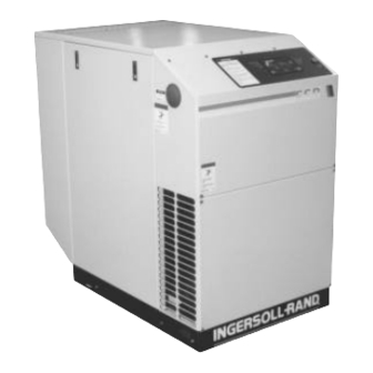
EP/HP/HXP 20 SE
EP/HP/HXP 25 SE
OPERATORS/
INSTRUCTION MANUAL
OPTIONS
®
APDD 567A
September 1998
Advertisement
Table of Contents


Need help?
Do you have a question about the EP 20 SE and is the answer not in the manual?
Questions and answers