Advertisement
Quick Links
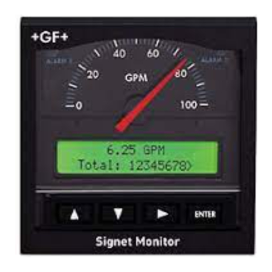
Signet 5500 Flow Monitor
*3-5500.090-1*
3-5500.090-1
Rev. L
01/12
CAUTION!
• Remove power to unit
before wiring input and
output connections.
• Follow instructions
carefully to avoid
personal injury.
Remove terminal blocks for easy wiring
1.
1. Power Connections
CAUTION!
Never connect 115 VAC or 230 VAC to rear power
terminals. High voltage AC will damage instrument and
void warranty.
= Double Insulated
= DC or AC power
Technical Notes:
• To reduce the possibility of noise interference, isolate AC power lines from signal lines.
• Maximum 4 to 20 mA loop impedance (sec. 6) is affected by the supply voltage.
English
Contents
1. Power Connections
2. Compatible Sensor Wiring
3. Sensor Pulse Output Connections
4. Auxiliary Pulse Output Connections
5. Totalizer Reset Connections
6. 4 - 20 mA Current Output Connections
7. Relay Connections
+
+
Gnd
Gnd
1
2
PLS
AUX
Total
output
output
reset
Std. Sensor
Open Collector
U L
Sensor
LISTED
77CJ
12-24 V
10 W
+
-
5500
Terminals
12-24 V
10 W
External power
supply
-
+
-
12 - 24 VDC
OR
12 - 24 VAC
+
3.
2.
2. Compatible Sensor Wiring
Std. Sensor
Open Collector
Sensor
8. Output Functions
9. Menu Functions
10. Parts and Accessories
11. Specifi cations
12. Quick Reference Menu Parameters
13. Troubleshooting
14. Maintenance
+
+
Gnd
Gnd
1
2
PLS
AUX
Total
output
output
reset
Std. Sensor
Open Collector
U L
Sensor
LISTED
77CJ
12-24 V
10 W
+
-
Signet Sensors:
Red
Black
Shield
Red
Black
Shield
5500
Termina ls
English
515
525
2000
2507
2536
2540
2100
2537
2551
2552
Advertisement

Related Manuals for GF Signet 5500


Summary of Contents for GF Signet 5500
- Page 1 English Signet 5500 Flow Monitor *3-5500.090-1* 3-5500.090-1 Rev. L 01/12 English Contents CAUTION! 1. Power Connections 8. Output Functions • Remove power to unit 2. Compatible Sensor Wiring 9. Menu Functions before wiring input and 3. Sensor Pulse Output Connections 10.
- Page 2 • External counter or accumulator inputs without internal open-collector excitation voltage and pull-up resistor. NPN sink input Input 28 VDC Other max. instrument Other 28 VDC instrument max. Input External power supply PNP source input 5500 5500 output output Terminals Terminals Signet 5500 Flow Monitor...
- Page 3 5 A @ 30 VDC, 5 A @ 125 VAC, or 3 A @ 250 VAC • An external heavy-duty relay must be used for devices with surge or operating currents that exceed the above specifi cations. Signet 5500 Flow Monitor...
- Page 4 8.5 Relay 1 and 2 outputs (sec 7): Relay outputs 1 and 2 can be independently confi gured as Low alarm, High alarm, Pulse or Totalizer output. Refer to diagrams A - C above for operation details. Signet 5500 Flow Monitor...
- Page 5 (sec. 9.2 J-M). Last calibration A↑ H. Last calibration: This display shows a user- defi ned setup date for maintenance records. This feature is not an internal timer or calendar. Signet 5500 Flow Monitor...
- Page 6 Signet fl ow sensor for each engineering unit of fl uid measured (published in fl ow sensor manual). Last calibration Setup date A↑ To return to To restore original value: VIEW menu: quick quick press press Signet 5500 Flow Monitor...
- Page 7 Auxiliary out logic Active Low or High A↑ To return to To restore original value: Active Low Logic (factory default) VIEW menu: quick quick press press Inactive (Off) Active (On) Active High Logic Active (On) Inactive (Off) Signet 5500 Flow Monitor...
- Page 8 • External contact closure overrides security feature (sec. 5) Noise emissions: EN55011 Safety: EN61010-1 Agency Approvals • CE, UL, CUL • Manufactured under ISO 9001 for Quality and ISO 14001 for Environmental Management. China RoHS (Go to www.gfsignet.com for details) Signet 5500 Flow Monitor...
- Page 9 • Relay 2 setpoint Pulse, 0.0001 - 99999. 90.000 GPM • AUX output mode Low or High, 0.0000 - 99999. Pulse • AUX output setpoint Pulse, 0.0001 - 99999. 1.0000 Gallons Last calibration date 00-00-00 to 39-39-99 01-01-98 Signet 5500 Flow Monitor...
- Page 10 0.0000 - 99999. 0.0000 volume • AUX output mode 1.0000 Pulse, 0.0001 - 99999. • AUX output setpoint Gallons AUX output pulse width 0.10 - 9999. seconds 0.10 seconds Last calibration date 00-00-00 to 39-39-99 01-01-98 Signet 5500 Flow Monitor...
- Page 11 4 mA adjust 3.0 to 5.0 mA 4.00 mA 20 mA adjust 19 to 21 mA 20.00 mA VIEW menu total reset On or Off access code AUX output pulse logic Active Low or Active High Signet 5500 Flow Monitor...
- Page 12 13. Troubleshooting Display Problem Solution Change fl ow timebase (S=Seconds, M=Minutes, H=Hours, Display timebase too large D=Days) in CALIBRATE menu to a smaller value (e.g. GPD to -- -- -- -- GPM) Relay 1 or 2 pulse width too large for Reduce Relay 1 or 2 pulse width setting (sec.
Need help?
Do you have a question about the Signet 5500 and is the answer not in the manual?
Questions and answers