Table of Contents
Advertisement
Quick Links
Advertisement
Table of Contents

Related Manuals for Chamberlain TPD10-05


Summary of Contents for Chamberlain TPD10-05
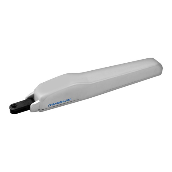
- Page 1 ® Mechanical & electrical installation TPD10-05...
- Page 2 WARNING / ATTENTION IMPORTANT FITTING AND OPERATING INSTRUCTIONS PLEASE START BY READING THESE IMPORTANT SAFETY RULES • SAVE THESE INSTRUCTIONS The manual consists of these operating instructions and the Declaration of Conformity. This safety alert symbol means "Caution" - failure to comply with such an instruction involves risk of personal injury or damage to property.
-
Page 3: Before You Begin
Optional accessories 1. Flashing lamp FLA1-LED Kit for cable extension of one 2. ECK7 installation unit. Consists of 7 m of cable 6-pole with identical colours, distribution box IP44, cable screw joints and fastening material 2 pieces with large 4-hole baseplate 3. -
Page 4: Technical Data
TECHNICAL DATA: Motor voltage Nominal power Max. power Max. thrust 300daN Spindle travel 300mm Cycles/24h 5-10 Rated operation time 4 min GATE TYPES The location of the motor installation depends on the type of gate. If the gate stop is on the floor the motor should also be installed as low as possible in order for the gate not to be distorted. -
Page 5: Installation Of Fittings
INSTALLATION OF FITTINGS First read all of the following 3 sections. It is important for the motor to be installed horizontally. The space between pillar and gate “Tensioning distance” is crucial for later operation. Precision is necessary. If you are not sure , attach fittings to the motor on a trial basis, hold it against the gate and measure for best position. - Page 6 TENSIONING DISTANCE The space between the fittings is called tensioning distance. When the gate is closed the trolley on the spindle is in the front and travels during the opening process towards the rear. Note: Adhere to tensioning distance under all circumstances! Dimensions see picture.
-
Page 7: Typical Configuration Of A Unit
TYPICAL CONFIGURATION OF A UNIT: 1. Motor 2. Control board 3. Photocell (active for closing), max. height 200 mm First photocell. 4. photocell (active for opening and closing), max. height 200 mm Second photocell (optional). 5. Flashing light (optional) Important visual information on the movement of the gate. 6. -
Page 8: Recommended Procedure
RECOMMENDED PROCEDURE: Fasten exterior installation box to wall, after previously measuring required distances and establishing correct position of drill- holes (Hardware not included). Baseplate for transformer is already pre-assembled (A). Push fastening clips in designated holes (B) . Push controlboard onto fastening clips (C). Fasten transformer onto baseplate using the large screw and large washer (D). - Page 9 TECHNICAL DATA OF MOTOR CONTROL: WIRING OF CONTROL / SUMMARY Voltage 230VAC / 50-60 Hz a) start with still dead 230Volts supply cable on the left side of the box. Transformer 230/24VAC minimum60VA b) Attach cable eye to ground wire. Then connect ground wire to base Output motor 24VDC max.
-
Page 10: Description Of Push Buttons
To enable the “Automatic Closing” Ω function, the Chamberlain failsafe photocell must be installed. The Chamberlain failsafe system (2-cable system) has small LEDs (light) that can be seen from the outside on both sides to indicate the status of the photocell. -
Page 11: Key Switch (Optional)
KEY SWITCH (OPTIONAL) The system can be operated by key switch. It is possible to operate COM PHOTO COM STOP/* 8.2 Ω only 1 wing or two wings. This depends on how the JUMPERS are used (connectors: key symbol and COM) E-LOCK (OPTIONAL) Model 203285... - Page 12 JUMPERS 1 / 2 Motor 1 or 2 motors are connected to the control board. FREE: both motors connected LINKED: only one motor connected 1/2 MOTOR STOP/8.2KΩ STOP / 8.2 KOhms OPEN / PED Defines if connector STOP / 8.2 KOhms is used for an emergency stop switch or for a safety edge.
- Page 13 PROGRAM TX4UNI Insert radio module on designated pins, if not pre-installed. The receiver has two channels CH1 and CH2. The respective LEDs CH1 and CH2 are assigned to these two channels. Receiving a signal from a programmed remote control button, CH1= P1 opens the gate partially.
-
Page 14: Initial Operation Basic Setting
INITIAL OPERATION BASIC SETTING Proceed step by step. If you are not sure, start again at the beginning. Take sufficient time to make these settings. Important: Before connecting the control board to the mains the jumper "RADIO" must be off. After connecting the control board to the mains, the diagnosis LED will flash 7 or 8 times. - Page 15 PROGRAMMING TRAVEL DISTANCES “ADVANCED” NOTE: With every time the button is pressed a position (time) is stored. (This allows programming of SOFT-STOP (slow travel) in order to adjust to application. Long or short phases of SOFT-STOP are possible. Both wings must be closed. Press P1 and P2 for approx.5-6 seconds until wing / motor 1 starts opening.Release buttons!!! Press P1 again.
-
Page 16: Indication Of The Diagnosis Led
INDICATION OF THE DIAGNOSIS LED Indication Description Remedy 1x blinking Motor 1 has insufficient connection to control board Green or white cable not wired or badly connected Check terminals precisely. Consider wire lengths 2x blinking Motor 2 has insufficient connection to control board Refer to 1x blinking 3x blinking Limits for motor 2 have not been accepted... - Page 17 An appropriate aerial with installation kit can be obtained from Chamberlain as an accessory with the product ref. no. ANT4X-1LM. Not recommended! Change gate! The gate can move in an uncontrolled (dangerous) manner if The gate must follow a slope.
- Page 20 Chamberlain GmbH Alfred-Nobel-Strasse 4 66793 Saarwellingen Germany www.chamberlain.eu diy@chamberlain.eu 114A4623D-en © Chamberlain GmbH, 2016...
Need help?
Do you have a question about the TPD10-05 and is the answer not in the manual?
Questions and answers