Table of Contents
Advertisement
Quick Links
UG-2020-12
EVAL-M3-302F User Guide
iMOTION™ Modular Application Design Kit
About this document
Scope and purpose
This User Guide provides an overview of the evaluation board EVAL-M3-302F including its main features, key
data, pin assignments and mechanical dimensions.
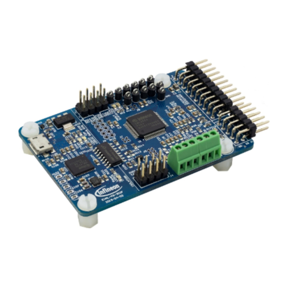
EVAL-M3-302F is an evaluation board as part of the iMOTION™ modular application design kit (MADK). This
board features and demonstrates Infineon's advanced motion control engine (MCE 2.0) technology for
permanent magnet motor drives over the full speed range.
The evaluation board EVAL-M3-302F was developed to support customers during their first steps designing
applications using permanent magnet motors via sensorless sinusoidal control.
The IMC302A contains two cores - the Motion Control Engine (MCE) and an additional microcontroller (MCU).
MCE support files and documentation will be available from the Infineon website. The MCU core-related CMSIS
pack can be downloaded from the KEIL IDE and this document does not cover those topics.
Intended audience
This User Guide is intended for all technical specialists who have a knowledge of motor control and high-power
electronics converters. The board is intended for use under laboratory conditions.
This board will be used during design in, for evaluation and measurement of characteristics, and proof of data
sheet specifications.
Note:
PCB and auxiliary circuits are NOT optimized for final customer design.
Table of contents
About this document ....................................................................................................................... 1
Table of contents ............................................................................................................................ 1
1
Important notice .................................................................................................................... 3
2
Safety precautions ................................................................................................................. 5
3
Introduction .......................................................................................................................... 6
4
EVAL-M3-302F main features ................................................................................................... 7
4.1
Functional description ............................................................................................................................ 8
4.2
IMC302A-F064 pinout description........................................................................................................... 9
4.3
EVAL-M3-302F board specifications...................................................................................................... 12
4.4
Connectors and pin assignment ........................................................................................................... 13
5
Getting started with EVAL-M3-302F ......................................................................................... 17
5.1
Setting up the Motion Control Engine (MCE) ........................................................................................ 18
5.1.1
iMOTION™ development tools and software .................................................................................. 19
5.1.2
MCEWizard setup overview .............................................................................................................. 20
User Guide
Please read the Important Notice and Warnings at the end of this document
Revision 1.1
2021-03-21
Advertisement
Table of Contents

Subscribe to Our Youtube Channel
Related Manuals for Infineon EVAL-M3-302FTOBO1


Summary of Contents for Infineon EVAL-M3-302FTOBO1
-
Page 1: Table Of Contents
The IMC302A contains two cores – the Motion Control Engine (MCE) and an additional microcontroller (MCU). MCE support files and documentation will be available from the Infineon website. The MCU core-related CMSIS pack can be downloaded from the KEIL IDE and this document does not cover those topics. - Page 2 EVAL-M3-302F User Guide iMOTION™ Modular Application Design Kit Table of contents 5.1.3 MCEDesigner setup overview ......................22 Working with the MCU ........................... 24 Hardware description of EVAL-M3-302F ................... 25 Motor current feedback circuitry ......................25 6.1.1 Motor shunt configuration ....................... 25 6.1.2 Motor external current feedback configuration and calculation ...........
-
Page 3: Important Notice
Infineon Technologies shall not be responsible for any damages resulting from the use of the Evaluation Boards and Reference Boards and/or from any information provided in this... - Page 4 EVAL-M3-302F User Guide iMOTION™ Modular Application Design Kit Important notice document. The customer is obliged to defend, indemnify and hold Infineon Technologies harmless from and against any claims or damages arising out of or resulting from any use thereof. Infineon Technologies reserves the right to modify this document and/or any information provided herein at any time without further notice.
-
Page 5: Safety Precautions
EVAL-M3-302F User Guide iMOTION™ Modular Application Design Kit Safety precautions Safety precautions Please note the following warnings regarding the hazards associated with development systems. Table 1 Safety precautions Warning: The DC link potential of this board is up to 1000 V . -
Page 6: Introduction
The PC interface provides a UART connection to the MCE as well as a serial wire debug (SWD) channel to the MCU. The EVAL-M3-302F evaluation board is available from Infineon. The features of this board are described in the main features chapter of this document, whereas the remaining paragraphs provide information to enable the customers to copy, modify and qualify the design for production according to their own specific requirements. -
Page 7: Eval-M3-302F Main Features
Modular Application Design Kit EVAL-M3-302F main features EVAL-M3-302F main features EVAL-M3-302F is an evaluation control board for motor control applications. The kit demonstrates Infineon’s motion control IC technology. The evaluation board characteristics: Control board for any permanent magnet motor with field oriented control ... -
Page 8: Functional Description
EVAL-M3-302F User Guide iMOTION™ Modular Application Design Kit EVAL-M3-302F main features Functional description Figure 2 shows the block diagram of the EVAL-M3-302F. The IMC302A-F064 provides a built-in, closed loop and sensorless control algorithm using the unique flexible Motion Control Engine (MCE) for permanent magnet motors, and additionally a boost or totem pole power factor correction (PFC). -
Page 9: Imc302A-F064 Pinout Description
EVAL-M3-302F User Guide iMOTION™ Modular Application Design Kit EVAL-M3-302F main features IMC302A-F064 pinout description The main part of the EVAL-M3-302F MADK control board is the IMC302A-F064 iMOTION™ motor control IC. Figure 3 depicts the pinout of the IMC302A-F064 IC. IMC302A-F064 comes in a 12 mm x 12 mm 64-pin LQFP package. - Page 10 EVAL-M3-302F User Guide iMOTION™ Modular Application Design Kit EVAL-M3-302F main features Table 2 lists the available pins of IMC302A-F064 with short descriptions. For more detailed information, please refer to the datasheet or hardware user manual for iMOTION™ IMC302A-F064 motor control IC. Table 2 IMC302A-F064 pinout description Pin name...
- Page 11 EVAL-M3-302F User Guide iMOTION™ Modular Application Design Kit EVAL-M3-302F main features AIN1 Analog input AIN2 Analog input AIN4 Analog input AIN7 Analog input AIN8 Analog input GPIO9 User configurable I/O, digital GPIO10 User configurable I/O, digital GPIO11 User configurable I/O, digital GPIO12 User configurable I/O, digital GPIO13...
-
Page 12: Eval-M3-302F Board Specifications
EVAL-M3-302F User Guide iMOTION™ Modular Application Design Kit EVAL-M3-302F main features P4.6 Programmable I/O P4.7 Programmable I/O EVAL-M3-302F board specifications Table 3 depicts the key specifications of the evaluation board EVAL-M3-302F. Table 3 EVAL-M3-302F board specifications Parameters Values Conditions / comments Host interface (not isolated) UART(TXD, RXD) 0 - VDD... -
Page 13: Connectors And Pin Assignment
EVAL-M3-302F User Guide iMOTION™ Modular Application Design Kit EVAL-M3-302F main features Connectors and pin assignment The EVAL-M3-302F consists of several functional groups, which enable an out-of-the-box, fully functional motor control system combined with additional interfaces and test points for more advanced use cases. Key information about the connections of the EVAL-M3-302F evaluation board is described below. - Page 14 EVAL-M3-302F User Guide iMOTION™ Modular Application Design Kit EVAL-M3-302F main features Pin No. Details Ground Gate kill signal – active low when over current is detected DCBSENSE DC bus positive voltage, scaled in 0-3.3 V range by a voltage divider Thermistor input Shunt voltage phase V Ground...
- Page 15 EVAL-M3-302F User Guide iMOTION™ Modular Application Design Kit EVAL-M3-302F main features Table 6 J3- MCU UART0 and SWD Name Pin name connectors SWDCLK User serial debug clock SWDIO User serial debug I/O +3.3 V +3.3 V power supply Ground Ground +3.3 V +3.3 V power supply RXD0_A...
- Page 16 EVAL-M3-302F User Guide iMOTION™ Modular Application Design Kit EVAL-M3-302F main features Name Pin name connector P1.1 Programmable I/O +3.3 V +3.3 V power supply Ground P0.13 Programmable I/O P0.8 Programmable I/O P0.12 Programmable I/O P0.9 Programmable I/O P0.11 Programmable I/O P0.10 Programmable I/O Table 10...
-
Page 17: Getting Started With Eval-M3-302F
EVAL-M3-302F User Guide iMOTION™ Modular Application Design Kit Getting started with EVAL-M3-302F Getting started with EVAL-M3-302F In order to run the motor system, the following components are required: iMOTION™ MADK control board (EVAL-M3-302F) Matching MADK power board with M3 connector ... -
Page 18: Setting Up The Motion Control Engine (Mce)
Refer to Chapters 0 and 5.1.3 as well as MCEWizard and MCEDesigner documentation for more information. 1. Get the latest IMC302A-F064 MCE software package available on www.infineon.com/imotion-software website. 2. Connect PC-USB connector on the on-board debugger to the PC via USB cable. -
Page 19: Imotion™ Development Tools And Software
The iMOTION™ Development Tool installers for MCEDesigner and MCEWizard are available for download via Infineon iMOTION website (http://www.infineon.com/imotion-software). All supported tools and software variants are listed there. Please visit this page periodically to check for tool/software updates. The isolated on-board debugger provides the USB to UART bridge between the PC and the target iMOTION™... -
Page 20: Mcewizard Setup Overview
“Welcome Page” for MCEWizard, where the MADK control board or power board can be selected via the pull-down list. Infineon continues to release new MADK controller and power boards. Therefore, it could happen that some of the newest power boards are not pre-configured in the MCEWizard tool and cannot be selected in the pull-down menu. - Page 21 EVAL-M3-302F User Guide iMOTION™ Modular Application Design Kit Getting started with EVAL-M3-302F Table 13 MCEWizard setup overview table Parameter Value Comment Power board selecting MADK power board name If no, select similar power board to modify Motor 1 shunt configuration Refer to the power board App Note Controller supply voltage Refer to the power board App Note...
-
Page 22: Mcedesigner Setup Overview
EVAL-M3-302F User Guide iMOTION™ Modular Application Design Kit Getting started with EVAL-M3-302F 5.1.3 MCEDesigner setup overview After installing the MCEDesigner installer, there is a shortcut for MCEDesigner on Windows desktop. Double- click on the shortcut to open MCEDesigner and then open “IMC302A_xx.irc” file (which was included in the “IMC302A-F064 MCE Software Package”... - Page 23 EVAL-M3-302F User Guide iMOTION™ Modular Application Design Kit Getting started with EVAL-M3-302F Figure 10 Program firmware and parameters in “Program IMC Controller” pop-up window To program only “Drive System Parameter” file into IMC302A-F064, click on “Tools” menu and select “Programmer” in the pull-down list. The pop-up window “Program IMC controller” will show up as in Figure 11. Click on the “Program Parameters”...
-
Page 24: Working With The Mcu
V DC voltage to the control board through some of the available 3.3 V access/test points, if the power board is not attached to the EVAL-M3-302F control board. All the latest firmware files for different types of iMOTION control ICs are available for download via Infineon iMOTION website (http://www.infineon.com/imotion-software). -
Page 25: Hardware Description Of Eval-M3-302F
EVAL-M3-302F User Guide iMOTION™ Modular Application Design Kit Hardware description of EVAL-M3-302F Hardware description of EVAL-M3-302F This chapter covers the hardware design of the EVAL-M3-302F in more detail. To enable users to make the EVAL- M3-302F evaluation board a basis for a new development or modification of their own systems, all necessary technical data such as schematics, layout and components are also included in this chapter. -
Page 26: Motor External Current Feedback Configuration And Calculation
EVAL-M3-302F User Guide iMOTION™ Modular Application Design Kit Hardware description of EVAL-M3-302F 6.1.2 Motor external current feedback configuration and calculation The shunt resistance R value can be found in the schematics or User Guide for the power board (for example, the leg shunt resistors are 30 mΩ... -
Page 27: Internal Amplifier Gain Configuration
EVAL-M3-302F User Guide iMOTION™ Modular Application Design Kit Hardware description of EVAL-M3-302F Figure 15 Current feedback configuration in MCEWizard for EVAL-M3-302F and EVAL-M3-CM615PN 6.1.3 Internal amplifier gain configuration For the current feedback, the iMOTION™ controller on this board has the internal amplifier which has four programmable gain settings: 1x, 3x, 6x and 12x. -
Page 28: Pfc Hardware Configuration
EVAL-M3-302F User Guide iMOTION™ Modular Application Design Kit Hardware description of EVAL-M3-302F PFC hardware configuration 6.2.1 PFC topology selection The EVAL-M3-302F control board applies to both PFC algorithms, boost mode and totem pole. The user needs to ensure that the topology configuration matches the power board hardware configuration. The topology configuration can be changed in MCEWizard as shown in Figure 17. -
Page 29: Pfc Current Feedback Configuration
EVAL-M3-302F User Guide iMOTION™ Modular Application Design Kit Hardware description of EVAL-M3-302F 6.2.3 PFC current feedback configuration Figure 19 depicts IPFC- current feedback sensing circuity on EVAL-M3-302F evaluation board. Please note that the default external amplification gain is less than 1 for current sense in this evaluation board. Figure 19 The PFC current feedback circuit for EVAL-M3-302F evaluation board Based on the principle of Kirchhoff's voltage law,... -
Page 30: Ac Voltage-Sensing Configuration
EVAL-M3-302F User Guide iMOTION™ Modular Application Design Kit Hardware description of EVAL-M3-302F The calculation formula for the threshold is as follows, ��35 ∗ ��27 − ��34 ∗ ��29 ∗ �� ���� �� �������������� ��27 + ��29 ∗ ��34 ∗ ����ℎ 6.2.4 AC voltage-sensing configuration Figure 21 shows the schematic of EVAL-M3-302F evaluation board with VAC sense. -
Page 31: Eval-M3-302F Analog Inputs And Their Mcewizard Setup
EVAL-M3-302F User Guide iMOTION™ Modular Application Design Kit Hardware description of EVAL-M3-302F The low-side resistor R11 or R16 for the AC voltage-sensing resistor divider on the controller board EVAL-M3- 302F is 15 kΩ, and should be configured in MCEWizard as shown in Figure 23. For the high-side resistor value, please refer to the User Guide of the corresponding power board. -
Page 32: Dc Bus-Sensing Configuration
EVAL-M3-302F User Guide iMOTION™ Modular Application Design Kit Hardware description of EVAL-M3-302F 6.3.1 DC bus-sensing configuration The low-side resistor R4 for the DC bus-sensing resistor divider on the controller board EVAL-M3-302F is 13.3 kΩ, and should be configured in MCEWizard as shown in Figure 25. For the high-side resistor value, please refer to the User Guide of the corresponding power board. - Page 33 EVAL-M3-302F User Guide iMOTION™ Modular Application Design Kit Hardware description of EVAL-M3-302F The typical value of R at 100°C is 5.388 kΩ for the IPM IFCM15P60GD that is used in EVAL-M3-CM615PN. If the setting temperature is 100°C, the shutdown value should be 2.08 V. Figure 26 External temperature-sensing input configuration in MCEWizard User Guide...
-
Page 34: Schematics Overview
35 µm copper by default, and its size is 65 mm × 45 mm. The PCB board thickness is 1.6 mm. Check Infineon’s website or get in contact with Infineon’s technical support team to obtain more detailed information and the latest Gerber files. - Page 35 EVAL-M3-302F User Guide iMOTION™ Modular Application Design Kit Hardware description of EVAL-M3-302F Figure 28 Top overlay print of the EVAL-M3-302F evaluation board Figure 29 depicts the bottom assembly print of the evaluation board. User Guide 35 of 44 Revision 1.1 2021-03-21...
- Page 36 EVAL-M3-302F User Guide iMOTION™ Modular Application Design Kit Hardware description of EVAL-M3-302F Figure 29 Bottom overlay print of the EVAL-M3-302F evaluation board The top layer routing of the PCB is provided in the following Figure 30. User Guide 36 of 44 Revision 1.1 2021-03-21...
- Page 37 EVAL-M3-302F User Guide iMOTION™ Modular Application Design Kit Hardware description of EVAL-M3-302F Figure 30 Top layer routing of the EVAL-M3-302F Figure 31 illustrates the bottom layer routing of the PCB. User Guide 37 of 44 Revision 1.1 2021-03-21...
- Page 38 EVAL-M3-302F User Guide iMOTION™ Modular Application Design Kit Hardware description of EVAL-M3-302F Figure 31 Bottom layer routing of the EVAL-M3-302F User Guide 38 of 44 Revision 1.1 2021-03-21...
-
Page 39: Bill Of Materials
EVAL-M3-302F User Guide iMOTION™ Modular Application Design Kit Bill of materials Bill of materials Table 14 provides the complete bill of materials for the EVAL-M3-302F board. Table 14 Bill of materials Qty. Part description Designator Part Number Manufacturer CAP SMD 10uF 16V 0805 885012206014 Wurth Electronics Inc. - Page 40 EVAL-M3-302F User Guide iMOTION™ Modular Application Design Kit Bill of materials Qty. Part description Designator Part Number Manufacturer RES SMD 1/10W 0ohm/DNI 0603 R8, R10, RC0603JR-07 R12, R14 RES SMD 1/10W 9.1Kohm 0603 R15, R101 RC0603JR-079K1L RES SMD 1/10W 10Kohm 0603 1% R17, R22, RC0603FR-0710KL R25, R30...
- Page 41 Modular Application Design Kit Bill of materials Qty. Part description Designator Part Number Manufacturer 8,TP9,TP10 ,TP11,TP12 IC MCU 32BIT 128KB FLASH IMC302A-F064 Infineon Technology LQFP64 IC MCU 32BIT 256KB FLASH U101 XMC4200_QFN48 Infineon Technology 48VQFN IC REG LINEAR 3.3V 1A SOT223- U102...
-
Page 42: Www.infineon.com/Imotion
All User Guides of the iMOTION™ MADK power boards are available at www.infineon.com/MADK Notice: Infineon’s product registration is now online. You can register your board online, and download additional information. There are three easy steps to register: 1. Go to www.Infineon.com/ login to myinfineon 2. -
Page 43: Revision History
EVAL-M3-302F User Guide iMOTION™ Modular Application Design Kit Reference Revision history Document Date of release Description of changes version 2020-05-22 First release, corrected calculation formula on page 29. 2021-03-21 Update getting started, PC interface User Guide 43 of 44 Revision 1.1 2021-03-21... - Page 44 WARNINGS Due to technical requirements products may contain dangerous substances. For information on the types © 2021 Infineon Technologies AG. in question please contact your nearest Infineon All Rights Reserved. Technologies office. Do you have a question about this Except as otherwise explicitly approved by Infineon...
Need help?
Do you have a question about the EVAL-M3-302FTOBO1 and is the answer not in the manual?
Questions and answers