
Related Manuals for THORLABS PDA8000-1


Summary of Contents for THORLABS PDA8000-1
- Page 1 Operation Manual Thorlabs Instrumentation PRO8000 (-4) / PRO800 Photo current module PDA8000 2012 __________________________________...
- Page 2 _______________________________________________ Version: Date: 27.03.2012 Copyright © 2012, Thorlabs ______________________________________________________________________________________________________ © 2012 Thorlabs...
-
Page 3: Table Of Contents
3.2.5 Reading the photo diode current (IPD) 3.2.6 Switch the bias voltage on and off (PDBIA) 3.2.7 Select the photo diode polarity (PDPOL) 3.2.8 Reading the optical power (POPT) 3.2.9 Selecting the measurement range (RANGE) 3.2.10 Querying the module type ______________________________________________________________________________________________________ © 2012 Thorlabs... - Page 4 3.4.7 Reading the STB by serial poll Service and Maintenance 4.1 General remarks 4.2 Troubleshooting Appendix 5.1 Warranty 5.2 Thorlabs “End of Life” policy (WEEE) 5.2.1 Waste treatment on your own responsibility 5.2.2 Ecological background List of abbreviations 5.3 List of figures 5.4 Certifications and compliances 5.5 Copyright...
- Page 5 We and our international partners are looking forward to hearing from you. In the displays shown by the PRO8 you may find the name PROFILE. PROFILE was the name of the manufacturer before it was acquired by Thorlabs and renamed to Thorlabs.
-
Page 6: General Description Of The Pda8000
PRO8000, PRO8000-4 or PRO800. All modules must only be operated with duly shielded connection cables. Only with written consent from Thorlabs may changes to single components be carried out or components not supplied by Thorlabs be used. This precision device is only dispatchable if duly packed into the complete original packaging including the plastic form parts. - Page 7 Mobile telephones, cellular phones or other radio transmitters are not to be used within the range of three meters of this unit since the electromagnetic field intensity may then exceed the maximum allowed disturbance values according to EN 50 082-1. ______________________________________________________________________________________________________ © 2012 Thorlabs...
-
Page 8: Features
Additionally the reference ground for the measurements can be adapted to the measurement setup. LabVIEW®- and LabWindows/CVI®-driver ® ® For the PDA8000 Thorlabs supplies LabVIEW - and LabWindows/CVI -drivers for MS Windows 32. Please refer to our homepage for latest driver updates. -
Page 9: Technical Data
Technical data ________________________________________________________________________________ 1.3 Technical data (All technical data are valid at 23 ± 5°C and 35 ±15% humidity) Photocurrent amplifier module PDA8000-1(2) General data Photodiode current range 10 nA ... 10 mA Resolution 16 bit Polarity of photodiode selectable Setting range of bias voltage (can be switched off) 0.1 V ... -
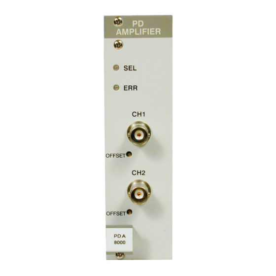
Page 10: Operating Elements At The Front Of The Module
1.4 Operating elements at the front of the module LED SELect LED error Connector jack input 1 Offset adjust input 1 Connector jack input 2 Offset adjust input 2 Figure 1 Operating elements on the PDA8000-2 front panel ______________________________________________________________________________________________________ © 2012 Thorlabs... -
Page 11: Presettings
BNC jack. Only one of the polarity settings of the PDA8000 (AG or CG) will then be correct. If in doubt, the correctly selected polarity yields a positive photo current on the display. ______________________________________________________________________________________________________ © 2012 Thorlabs... -
Page 12: Operating The Pda8000
- 0.1234 nA TUNE 2.1.2 Selecting a module Select a module for further input by setting the cursor to the channel number of the desired module. Use the soft key Pressing will lead to the channel menu ______________________________________________________________________________________________________ © 2012 Thorlabs... -
Page 13: Functions In The Channel Menu
BIA2 = OFF BIA1 = OFF RNG2 =10.00nA RNG1 =10.00nA POL2 = CG If you use the PDA8000-FWD: POL1 = CG Ifwd=1.1234mA Ifwd= 3.000mA Ufwd=1.234 V Ufwd= 1.551 V MEASURE Ifwd MEASURE Ifwd I2=+ 0.1234nA 0.1234nW ______________________________________________________________________________________________________ © 2012 Thorlabs... -
Page 14: Changing Parameters
Some parameters can not be changed, as they are measurement values (i.e. the photo diode current) or may not be changed during bias voltage switched on. In these cases access is denied indicated by a long beep. ______________________________________________________________________________________________________ © 2012 Thorlabs... -
Page 15: Selecting The Polarity Of The Photo Diode
If for example the photo diode shall work with 3.000 V bias voltage this can be entered in the channel menu : 3.00 V for input 1 3.00 V for input 2 (Refer to chapter 2.2.2, "Changing parameters" on page 10) ______________________________________________________________________________________________________ © 2012 Thorlabs... -
Page 16: Switching On The Bias Voltage Of The Photo Diode
0.250 % f.s. 10 nA 0.1 pA 0.800 % f.s. To set for example the measurement range to 1 mA full scale, enter RNG1 =1.000mA for input 1 RNG2 =1.000mA for input 2 In the channel menu. ______________________________________________________________________________________________________ © 2012 Thorlabs... -
Page 17: Measuring The Forward Voltage (Option Pda8000-Fwd)
Possible reasons for error messages during forward voltage measurement ACCURACY ! Insufficient measurement accuracy (non-linearities or noise) OVERFLOW ! The requested forward current could not be reached, even with the max. possible voltage. Possibly, no photo diode connected or bad connection. ______________________________________________________________________________________________________ © 2012 Thorlabs... -
Page 18: Communication With A Control Computer
Is a numerical value with sign in integer notation. Examples: 14356789432 (Refer to IEEE488.2 (8.7.2)) Numeric response data Type 2 (<NR2>) Is a numerical value with or without sign in floating point notation without exponent. Examples: +1.1 -22.1 14356.789432 (Refer to IEE488.2 (8.7.3)) ______________________________________________________________________________________________________ © 2012 Thorlabs... -
Page 19: Commands
Reads the sensitivity () of the monitor diode in [:CALPD:SET <NR3><LF>] ":CALPD:MIN?" Reads the allowed minimum sensitivity () of the monitor diode in A/W [:CALPD:MIN <NR3><LF>] ":CALPD:MAX?" Reads the allowed maximum sensitivity () of the monitor diode in A/W [:CALPD:MAX <NR3><LF>] ______________________________________________________________________________________________________ © 2012 Thorlabs... -
Page 20: Programming The Forward Current (Ifwd)
“ELCH” on output string position <NR1> (1...8) Reading: ":IPD:ACT?" Reads the actual photo diode current [:IPD:ACT <NR3><LF>] ":IPD:MIN_R?" Reads I – ADC = 0000 [:IPD:MIN_R <NR3>] ":IPD:MAX_R?" Reads I – ADC = FFFF [:IPD:MAX_R <NR3>] ______________________________________________________________________________________________________ © 2012 Thorlabs... -
Page 21: Switch The Bias Voltage On And Off (Pdbia)
3.2.7 Select the photo diode polarity (PDPOL) NOTE Please first select the desired port with the command ":PORT" Programming: ":PDPOL AG" Selects anode on ground ":PDPOL CG" Selects cathode on ground Reading: ":PDPOL?" Reads the monitor diode polarity [:PDPOL AG<LF>] [:PDPOL CG<LF>] ______________________________________________________________________________________________________ © 2012 Thorlabs... -
Page 22: Reading The Optical Power (Popt)
":RANGE 4" Selects the 10 μA range ":RANGE 5" Selects the 100 μA range ":RANGE 6" Selects the 1 mA range ":RANGE 7" Selects the 10 mA range Reading: ":RANGE?" Reads the selected range [:RANGE <NR1><LF>] ______________________________________________________________________________________________________ © 2012 Thorlabs... -
Page 23: Querying The Module Type
– DAC = 0000 BIAS [:VBIAS:MIN_W <NR3><LF>] ":VBIAS:MAX_W?" Reads U – DAC = FFFF BIAS [:VBIAS:MAX_W <NR3><LF>] ":VBIAS:START?" Reads the start bias voltage for “ELCH” [:VBIAS:START <NR3><LF>] ":VBIAS:STOP?" Reads the stop bias voltage for “ELCH” [:VBIAS:STOP <NR3><LF>] ______________________________________________________________________________________________________ © 2012 Thorlabs... -
Page 24: Reading The Forward Voltage (Vfwd)
– ADC = FFFF [:VFWD:MAX_R <NR3><LF>] NOTE Before measuring the forward voltage, you should select a suited forward current with the command ":IFWD". If the photo diode is poled wrong, you will measure a voltage of abt. 10V. ______________________________________________________________________________________________________ © 2012 Thorlabs... -
Page 25: Ieee Error Messages Of An Pda8000
Insufficient measurement accuracy due to non-linearities or noise. 1406," Ufwd measurement failed – voltage overflow" Possible reason: The requested forward current could not be reached, even with the max. possible voltage. Possibly, no photo diode connected or bad connection.. ______________________________________________________________________________________________________ © 2012 Thorlabs... -
Page 26: Status Reporting
The PDA8000 has no own device error registers. You can only use the PRO8000 (-4) / PRO800 mainframe status registers shown here. Output buffer ERROR Queue or serial poll Service Request Generation Figure 2 The PRO8000 (-4)/ PRO800 register ESR, ESE, STB and SRE ______________________________________________________________________________________________________ © 2012 Thorlabs... -
Page 27: Standard Event Status Register (Esr)
(Error AVailable) This bit is high as long as there are errors in the error queue. (command FINished) This bit is high, after a command has finished and all bits of the STB have been set. ______________________________________________________________________________________________________ © 2012 Thorlabs... -
Page 28: Service Request Enable Register (Sre)
3.4.7 Reading the STB by serial poll If the controller does not support auto serial poll, the service request can also be detected via manual serial poll. If bit 6 is logical 1, a service request was asserted. ______________________________________________________________________________________________________ © 2012 Thorlabs... -
Page 29: Service And Maintenance
4 Service and Maintenance 4.1 General remarks The PDA8000 modules don’t need any maintenance by the user. In order to ensure best performance, accuracy and reliable operation, Thorlabs recommends a recalibration cycle of 24 months. 4.2 Troubleshooting In case that one module of your PRO8000 (-4) / PRO800 system shows malfunction please check the following items: ... - Page 30 Do you have chosen an appropriate measurement range for your application? ":RANGE <NR1>" Use the command or use the channel menu to select a higher or lower sensitivity If this does not help to resolve your trouble, please contact Thorlabs’ Tech Support. (refer section 5.6, “...
- Page 31 Troubleshooting ________________________________________________________________________________ Addresses ” on page 35 ______________________________________________________________________________________________________ © 2012 Thorlabs...
-
Page 32: Appendix
For warranty repairs or service the unit must be sent back to Thorlabs (Germany) or to a place determined by Thorlabs. The customer will carry the shipping costs to Thorlabs, in case of warranty repairs Thorlabs will carry the shipping costs back to the customer. -
Page 33: Thorlabs "End Of Life" Policy (Weee)
5.2.1 Waste treatment on your own responsibility If you do not return an “end of life” unit to Thorlabs, you must hand it to a company specialized in waste recovery. Do not dispose of the unit in a litter bin or at a public waste disposal site. -
Page 34: Ecological Background
Thorlabs “End of Life” policy (WEEE) ________________________________________________________________________________ 5.2.2 Ecological background It is well known that WEEE pollutes the environment by releasing toxic products during decomposition. The aim of the European RoHS directive is to reduce the content of toxic substances in electronic products in the future. -
Page 35: List Of Abbreviations
Numeric Response data of type 2 Numeric Response data of type 3 Message AVailable) Master Summary Status Personal Computer Photo Diode ReQuest Service Message Selected Device Clear SELect Service Request Enable Register Service ReQuest STatus Byte Register TRiGger ______________________________________________________________________________________________________ © 2012 Thorlabs... -
Page 36: List Of Figures
List of figures ________________________________________________________________________________ 5.3 List of figures Figure 1 Operating elements on the PDA8000-2 front panel Figure 2 The PRO8000 (-4)/ PRO800 register ESR, ESE, STB and SRE Figure 3 Crossed out “wheelie bin” symbol ______________________________________________________________________________________________________ © 2012 Thorlabs... -
Page 37: Certifications And Compliances
Part 15, Subpart B Compliance demonstrated using high-quality shielded interface cables. Compliance demonstrated with the PDA8000 series modules installed in the Thorlabs PRO8x series of mainframes. Emissions, which exceed the levels required by these standards, may occur when this equipment is connected to a test object. -
Page 38: Copyright
User Manual. Should you require further information on this product, or encounter specific problems that are not discussed in sufficient detail in the User Manual, please contact your local Thorlabs dealer or system installer. -
Page 39: Addresses
Thorlabs, Inc. Thorlabs Ltd. sales@thorlabs.com sales.uk@thorlabs.com techsupport@thorlabs.com techsupport.uk@thorlabs.com Europe Scandinavia Thorlabs GmbH Thorlabs Sweden AB europe@thorlabs.com scandinavia@thorlabs.com France Brazil Thorlabs SAS Thorlabs Vendas de Fotônicos Ltda. sales.fr@thorlabs.com brasil@thorlabs.com Japan China Thorlabs Japan, Inc. Thorlabs China sales@thorlabs.jp chinasales@thorlabs.com ______________________________________________________________________________________________________ © 2012 Thorlabs...
Need help?
Do you have a question about the PDA8000-1 and is the answer not in the manual?
Questions and answers