Table of Contents
Advertisement
Advertisement
Table of Contents

Related Manuals for Grundfos PM 1


Summary of Contents for Grundfos PM 1
- Page 1 GRUNDFOS INSTRUCTIONS PM 1, PM 2 Installation and operating instructions...
-
Page 2: English (Gb
PM 1, PM 2 English (GB) Installation and operating instructions....... . . 3 (AR) ة... -
Page 3: Table Of Contents
Original installation and operating instructions Technical data These installation and operating instructions 16.1 Technical data, PM 1 describe Grundfos PM 1 and PM 2 pressure 16.2 Technical data, PM 2 managers. Sections 1-6 give the information Disposing of the product necessary to be able to unpack, install and start up the product in a safe way. -
Page 4: Receiving The Product
3.2 Mechanical installation, PM 1 3. Installing the product PM 1 can be installed in systems with or without a pressure tank. Install the pressure manager on the outlet side of the pump. See fig. 4. -
Page 5: Mechanical Installation, Pm
Start pressure set Maximum height [bar] 1.5* Fig. 3 Installation positions, PM 1 Pos. D in fig 2: Do not install taps between the pump and the pressure manager. Default setting. See section 9.1 Start and stop according to water... - Page 6 Pos. B in fig. 4: To achieve correct operation, the pump must at least be able to provide the outlet pressures in the table below. Minimum outlet pressure Operating mode Start Start and stop Start and stop pressure set according to with 1 bar water differential...
-
Page 7: Electrical Connection, Pm 1 And Pm
3.4.3 Alternative power supply "Alarm" stopped due to an operating PM 1 and PM 2 can be powered by a generator or fault. other alternative power supplies, provided that the See section 15.1 Fault requirements for the power supply are fulfilled. - Page 8 4.2 Operating panel, PM 2 4.2.1 DIP switches, PM 2 PM 2 has a number of settings which can be made with the DIP switches behind the operating panel. See fig. 9. OFF/ON OFF/ON 1.5 BAR 1 +1.0 START START +1.0 +1.0 +1.0...
- Page 9 DIP switch Description Default setting No. Name Start pressure With these DIP switches you can set the start pressure from 1.5 to 5.0 bar in steps of 0.5 bar. All set to OFF; Example: START start pressure = 1.5 DIP switch 1 = "ON" DIP switch 2 = "ON"...
-
Page 10: Starting Up The Product
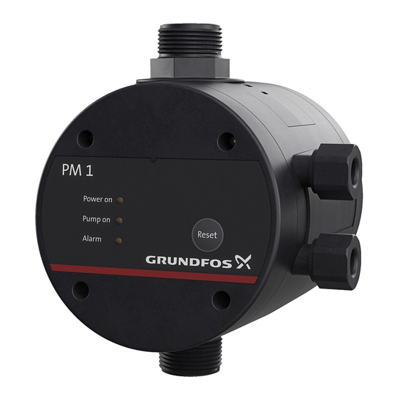
3. Check that the "Pump on" and "Alarm" indicator systems lights as well as all the green light fields in the PM 1 is for basic flexibility, and PM 2 for all-round pressure scale illuminate briefly. control if you demand more. -
Page 11: Operation, Pm
With the default setting, the pump will not for at least 10 seconds. stop until it reaches its maximum pressure. 10. Functions, PM 1 9.1.1 Starting and stopping conditions 10.1 Anti cycling Starting conditions... -
Page 12: Dry-Running Protection
10.2 Dry-running protection 11.2 Anti cycling The pressure manager incorporates dry-running To avoid inadvertent starts and stops of the pump in protection that automatically stops the pump in case case of a failure in the installation, the anti-cycling of dry running. function can be enabled. -
Page 13: Dry-Running Protection
12. Frost protection 11.4 Dry-running protection The pressure manager incorporates dry-running If the pressure manager is exposed to frost in protection that will automatically stop the pump in periods of inactivity, the pressure manager and the case of dry running. piping system must be drained before the pressure manager is taken out of operation. -
Page 14: List Of Alarms, Pm
13. List of alarms, PM 1 Indication Alarm Cause "Alarm" is permanently on. Dry running. The pump has been running without water. The pump is cycling. "Alarm" is flashing. Cycling. Note: Will only occur if the anti-cycling function is enabled. See section 9.3 Power supply... -
Page 15: Fault Finding, Pm
Leakage in the pipework. Check and repair the pipework. stops. Leaky non-return valve. Clean or replace the non-return valve.* A valve close to the PM 1 outlet Open the valve. has been closed. The pump does not The pump cannot deliver the Replace the pump. -
Page 16: Fault Finding, Pm 2
15.2 Fault finding, PM 2 Fault Cause Remedy The green light The fuses in the electric Replace the fuses. If the new fuses also blow, field for "0 bar" installation have blown. check the electric installation. is off even if the The earth leakage circuit breaker Cut in the circuit breaker. - Page 17 DIP switch 5 is set to "ON", but no pressure tank has been installed in the system. 12. The red "Alarm" Pressure sensor fault. indicator light Repair or replace the pressure manager.* flashes four times. See service instructions on www.grundfos.com > Product Center.
-
Page 18: Technical Data
16. Technical data 16.2 Technical data, PM 2 16.1 Technical data, PM 1 Data 230 V 115 V 1 x 220-240 1 x 110-120 Data 230 V 115 V Supply voltage 1 x 220-240 1 x 110-120 Maximum inductive Supply voltage... - Page 19 ة ات التقني البيان PM 2 ،ة ات التقني البيان 16.2 1 6 . 2 . 1 6 PM 1 ،ة ات التقني البيان 16.1 فول ت فول ت ات البيان 1 6 . 1 - 110 × 1 - 220 × 1 فول...
- Page 20 .( خل ل حس اس الض غط . الض وء " Alarm " ن المبي *.أص لح أو اس تبدل م دير الض غط األحم ر ي ومض .مرات *انظ ر تعليم ات الخدم ة عل ى موق ع الوي ب www.grundfos.com > Product Center...
- Page 21 PM 2 ،تحدي د العط ل وإص الحه 15.2 1 5 . 2 اإلص الح الس بب العط ل اس تبدل المص ھرات. إذا احترق ت المص ھرات الجدي دة ( المص ھرات ف ي التركي ب . حق ل الض وء .ائي...
- Page 22 PM 1 ،تحدي د العط ل وإص الحه 15.1 1 5 . 1 اإلص الح الس بب العط ل اس تبدل المص ھرات. إذا احترق ت المص ھرات ( المص ھرات ف ي التركي ب . الض وء المبي ن...
- Page 23 PM 1 ،قائم ة اإلن ذارات . 1 3 الس بب اإلن ذار الدالل ة .المض خة كان ت ت دور ب دون م اء .دوران ج اف ." مض اء دائم ا Alarm" .رارا ف تك تغل وتتوق خة تش...
- Page 24 الحماي ة م ن الثل ج الحماي ة م ن ال دوران الج اف 11.4 1 1 . 4 . 1 2 يتض من م دير الض غط حماي ة م ن ال دوران الج اف ال تي ،إذا تع رض م دير الض غط إل ى الثل ج ف ي ف ترات ال ال نش اط .المض...
- Page 25 من ع التش غيل والتوق ف المتك رر 11.2 الحماي ة م ن ال دوران الج اف 10.2 1 1 . 2 1 0 . 2 ير رر غ ف المتك غيل والتوق ات التش ب عملي لتجن يتض من م دير الض غط حماي ة م ن ال دوران الج اف ال تي توق ف ،المقص...
- Page 26 تش غيل نفس ھا آلي ا عن د ع ودة إم داد الق درة وت دور لم دة .إل ى أن تبل غ ض غطھا األقص ى .ث وان عل ى األق ل ح االت التش غيل واإليق اف 9.1.1 PM 1 ،الوظ ائف 9 . 1 . 1 . 1 0 ح االت التش غيل...
- Page 27 ام إذا م الع للتحك PM 2 ية، و ة األساس للمرون PM 1 يك ون " وأيض ا جمي ع حق ول األض واء Alarm " ن المبي .كن ت تطل ب المزي د الخض راء ف ي المقي اس الم درج للض غط تض يء...
- Page 28 مفت اح ي بط االفتراض الض الوص ف االس م ال رقم غيل غط التش ض ھ ذه ض بط ض غط التش غيل م ن اتيح تخدام مف ك باس يمكن .ب ار ب ار بت درجات إل ى الجمي...
- Page 29 PM 2 ، ف ي اتيح مف 4.2.1 PM 2 ،لوح ة التش غيل 4 . 2 . 1 4 . 2 ل ه ع دد م ن الض بطات ال تي يمك ن عملھ ا باس تخدام PM 2 خل...
- Page 30 وظ ائف التحك م PM 2 و PM 1 ،ائي يل الكھرب التوص 3 . 4 PM 1 ،لوح ة التش غيل خطر 4 . 1 ص دمة كھربائي ة - الوف اة أو إص ابة شخص ية خط يرة...
- Page 31 ف ي الش كل الموض ع لتحقي ق التش غيل الص حيح، يج ب أن تك ون المض خة ق ادرة .عل ى األق ل عل ى توف ير ض غوط الخ روج ف ي الج دول أدن اه ض غط الخ روج األدن ى نم...
- Page 32 اع األقص االرتف ض بط ض غط التش غيل []م []ب ار 1,5 * PM 1 ،مواض ع التركي ب 3 ش كل 3 ل ك ش ف ي الش كل الموض ع .ال ترك ب حنفي ات بي ن المض خة وم دير الض غط...
- Page 33 ال يج ب تع ريض م دير الض غط للمط ر وض وء الش مس تأك د م ن أن فولتي ة وت ردد المنت ج تطابق ان فولتي ة وت ردد .ر المباش .موق ع التركي ب PM 1 ،انيكي ب الميك التركي تركي ب المنت ج...
- Page 34 ب والتش تزم التركي يل المعلوم ات . تق دم األقس ام PM 2 و PM 1 جرون دفوس .دة ة الجي ة للممارس وانين المقبول والق الض رورية ال تي تمكن ك م ن إخ راج المنت ج م ن عبوت ه...
-
Page 35: Appendix
Appendix 1x115/230 V 1x230 V 50/60 Hz, PE 50/60 Hz, PE Fig. 1 Fig. 2 11.5 Fig. 3... - Page 36 Fig. 4...
-
Page 37: Declaration Of Conformity
Declaration of conformity GB: EU declaration of conformity : إق رار مطابق ة We, Grundfos, declare under our sole responsibility that the products ن أن المنتجي ة ب ؤوليتنا الفردي ى مس دفوس، بمقتض ن، جرون ر نح نق PM1, PM2, to which the declaration below relates, are in conformity ،... - Page 38 Argentina China Hong Kong Bombas GRUNDFOS de Argentina S.A. GRUNDFOS Pumps (Shanghai) Co. Ltd. GRUNDFOS Pumps (Hong Kong) Ltd. Ruta Panamericana km. 37.500 Centro 10F The Hub, No. 33 Suhong Road Unit 1, Ground floor Industrial Garin Minhang District Siu Wai Industrial Centre 1619 Garín Pcia.
- Page 39 Malaysia Serbia Turkey GRUNDFOS Pumps Sdn. Bhd. Grundfos Srbija d.o.o. GRUNDFOS POMPA San. ve Tic. Ltd. 7 Jalan Peguam U1/25 Omladinskih brigada 90b Sti. Glenmarie Industrial Park 11070 Novi Beograd Gebze Organize Sanayi Bölgesi 40150 Shah Alam Phone: +381 11 2258 740...
- Page 40 99064499 0319 ECM: 1255360 www.grundfos.com...
Need help?
Do you have a question about the PM 1 and is the answer not in the manual?
Questions and answers