Table of Contents
Advertisement
1. Introduction....................................................................... 3
1.1 Overview................................................................3
1.2 Hardware Specifications..........................................4
1.3 Software Specifications.......................................... 5
2. Board Installation.............................................................. 6
2.1 Unpacking.............................................................. 6
2.2 Installation.............................................................. 6
3. S1564 On Board Resource Settings................................. 7
3.1 S1564 Board Layout & Jumper Locations................ 7
3.2 Quick Reference for Jumpers.................................. 8
3.3 CMOS RTC............................................................12
3.4 Speaker Connector.................................................. 12
3.5 Turbo Switch.......................................................... 12
3.6 Turbo LED Connect................................................ 12
3.7 Reset Connector..................................................... 13
3.8 Flash EPROM Jumpers.......................................... 13
3.9 CMOS & Password Reset...................................... 13
3.10 DRAM Installation................................................ 14
3.11 CPU Installation.................................................... 17
3.12 Cache Memory.................................................... 18
3.13 Understanding Different Clock Speeds................... 19
3.14 Peripheral Device Installation................................. 20
3.15 Connecting The Power Supply...............................21
4. A w ard BIOS Configuration................................................22
4.1 Entering Setup....................................................... 23
4.2 Control Keys......................................................... 24
4.3 Getting Help........................................................... 25
4.4 The Main Menu...................................................... 25
4.5 Standard CMOS Setup Menu...................................27
4.6 BIOS Features Setup.............................................. 30
4.7 Chipset Features Setup............................................ 33
4.7.1 Power Management Setup........................ 38
4.8 PCI Slot Configuration.............................................40
4.9 Integrated Peripherals............................................. 42
4.10 Load Setup Defaults.............................................. 43
4.11 Password Setting................................................... 43
4.12 IDE HDD Auto Detection..................................... 45
4.13 Save & Exit Setup................................................. 45
4.14 Keyboard Setting Functions....................................46
S1564-001-01 www.tyan.com
Table Of Contents
1
Advertisement
Table of Contents

Related Manuals for TYAN TOMCAT IVS D


Summary of Contents for TYAN TOMCAT IVS D
-
Page 1: Table Of Contents
4.7.1 Power Management Setup......38 4.8 PCI Slot Configuration..........40 4.9 Integrated Peripherals..........42 4.10 Load Setup Defaults..........43 4.11 Password Setting........... 43 4.12 IDE HDD Auto Detection........45 4.13 Save & Exit Setup..........45 4.14 Keyboard Setting Functions........46 S1564-001-01 www.tyan.com... - Page 2 Award BIOS/Flash are trademarks of Award Software International Inc. AMI BIOS is a trademarks of American Megatrends Inc. IBM,PC,AT,PS/2 are trademarks of IBM Corporation INTEL,Pentium are trademarks of Intel Corporation. Cyrix is a trademark of Cyrix Corp. Copyright c 1996 TYAN Computer Corp. Tomcat IV, S1564. S1564-001-01 www.tyan.com...
-
Page 3: Introduction
S1564D's support for dual Pentium processors, you can start a system with just one CPU, and later add another, when more processing power is required. To provide you safer way of operating your system, Tyan has also incorporated LM78 (Option) System Hardware Monitor and Intel LANDesk Client Manager (LDCM) into the S1564S/D board design (See Appendix for details). -
Page 4: Hardware Specifications
EIDE Mode 0 through Mode 4 hard drives/CDROMs • Supports DMA (Busmaster) mode 1 and 2. ( Busmaster driver on web at www.tyan.com) Enhanced I/O • Multi-mode bi-directional parallel port that • Supports standard, EPP and ECP modes. -
Page 5: Software Specifications
Mouse • On-board PS/2 mouse header (for use with PS/ 2 mouse connector + cable - Tyan PN# S1607-001-01) Expansion • 4 32-bit Busmastering PCI slots • 5 16-bit ISA slots (One ISA and one PCI shared slot) 1.3 Software Specifications BIOS •... -
Page 6: Board Installation
2.2 Installation You are now ready to install your mainboard. The mounting hole pattern of the S1564S/D matches the "Baby AT" system board spec. It is assumed that the chassis is for a standard IBM XT/AT form factor. S1564-001-01 www.tyan.com... -
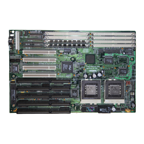
Page 7: S1564 On Board Resource Settings
••• 82093AA Only on S1564D •• 82439HX CPU 1 •• •• •• •• •• CPU 0 • • • • • • • • • J19 J20J21 •••• CON9 •• •• ••••• •• •• •••• •••• pin 1 S1564-001-01 www.tyan.com... -
Page 8: Quick Reference For Jumpers
166 MHz 200 MHz 233 MHz CPU V oltage Select All Pentium P54C and AMD K5 ===> 3.5V All Pentium MMX P55C ========> 2.8V AMD K6-PR166 and K6-PR200===> 2.9V AMD K6-PR233 ==============> 3.2V 2.8V 2.9V 3.2V 3.3V 3.4V 3.5V S1564-001-01 www.tyan.com... - Page 9 Pentium chips. Check with your CPU vendor for more info about s-spec numbers. DRAM Voltage Setting:J1, J2, J11, J12, J8, J9, & J10 Damage to system can result if these are set incorrectly! V olts Default 5V 3.3V Off S1564-001-01 www.tyan.com...
- Page 10 CPU FAN 1: J67 (PIN 2 is +12V) CPU FAN 2: J68 (PIN 2 is +12V) HDD LED: J24 Pinout Assignments Cathode Anode Cathode Anode Pins 1 and 2 are for primary IDE channel. Pins 3 and 4 are for secondary IDE channel. S1564-001-01 www.tyan.com...
- Page 11 Turbo LED Connector: J25 Pinout Assignment Cathode Anode Flash EEPROM: J48 This jumper should be left at the factory default. ON OFF OFF ON InfraRed Interface: Con7 and Con9 Pinout Assignment Signal In Signal Out PS/2 Pinout(J5): Ground Data Keyboard Connector S1564-001-01 www.tyan.com...
-
Page 12: Cmos Rtc
(J26) for the cable that may come with the case. 3.6 Turbo LED Connector Installation The TURBO LED on the front case panel can indicate the current speed status of the system. The TURBO LED connector should be installed to J25 in the correct direction. S1564-001-01 www.tyan.com... -
Page 13: Reset Connector
Short jumper J46. c. Wait for 5 seconds then remove the jumper from J46. d.Then power on the system again. By doing the above procedures, your password will be erased and the CMOS will be reset to the BIOS defaults. S1564-001-01 www.tyan.com... -
Page 14: Dram Installation
2MB*2 (4MB*2) (4MB*2) (4MB*2) 12MB 20MB 28MB 2MB*2 (8MB*2) (8MB*2) (8MB*2) 20MB 36MB 52MB 2MB*2 (16MB*B (16MB*2) (16MB*2) 4MB 36MB 68MB 100MB 2MB*2 (32MB*2) (32MB*2) (32MB*2) 4MB 68MB 132MB 196MB 2MB*2 (64MB*2) (64MB*2) (64MB*2) 4MB 132MB 260MB 388MB S1564-001-01 www.tyan.com... - Page 15 (4MB*2) (4MB*2) (4MB*2) 64MB 72MB 80MB 88MB 32MB*2 (8MB*2) (8MB*2) (8MB*2) 64MB 80MB 96MB 112MB 32MB*2 (16MB*2) (16MB*2) (16MB*2) 64MB 96MB 128MB 160MB 32MB*2 (32MB*2) (32MB*2) (32MB*2) 64MB 128MB 192MB 256MB 32MB*2 (64MB*2) (64MB*2) (64MB*2) 64MB 192MB 320MB 448MB S1564-001-01 www.tyan.com...
- Page 16 (4MB*2) (4MB*2) (4MB*2) 128MB 136MB 144MB 152MB 64MB*2 (8MB*2) (8MB*2) (8MB*2) 128MB 144MB 160MB 176MB 64MB*2 (16MB*2) (16MB*2) (16MB*2) 128MB 160MB 192MB 224MB 64MB*2 (32MB*2) (32MB*2) (32MB*2) 128MB 192MB 256MB 320MB 64MB*2 (64MB*2) (64MB*2) (64MB*2) 128MB 256MB 384MB 512MB S1564-001-01 www.tyan.com...
-
Page 17: Cpu Installation
4. Press the lever down. The top plate will slide forward. You will feel some resistance as the pressure starts to secure the CPU in the socket. This is normal and will not damage the CPU. The lever should snap into place at the side of the socket. S1564-001-01 www.tyan.com... -
Page 18: Cache Memory
BIOS setup. w The BIOS will auto detect the cache size so a you don't need to change any jumpers. w The mainboard has an 11 bit tag built on board so cachability of main memory is to 512MB. S1564-001-01 www.tyan.com... -
Page 19: Understanding The Different Clock Speeds
25MHz PCI bus speed. Since all of the Cyrix 6x86 CPU's use a x2 mulitplier, the 100MHz P120+ must run on a 50MHz host bus. The PCI speed will then be at 25MHz. S1564-001-01 www.tyan.com... -
Page 20: Peripheral Device Installation
If a PCI-Bus interface card is to be installed in the system, any one of the five PCI-Bus slots can support either a Master or a Slave device. After installing the peripheral controllers, the user should check everything again, and prepare to power-on the system. S1564-001-01 www.tyan.com... -
Page 21: Connecting The Power Supply
Orient the connectors so the black wires are in the middle of the 5V power supply. Caution: Some power supplies also include "3V" connectors. The connection wires normally have two colors with 3 black wires on one side. Please be very careful. Don't to use the wrong connec- tor. S1564-001-01 www.tyan.com... -
Page 22: A W Ard Bios Configuration
You may need to hold the lead at an angle to line it up.Once you have the guide pins aligned, press the lead connector so that the plastic clips on the lead snap into place and secure the lead to the connec- tor. Connecting 5V power supply S1564-001-01 www.tyan.com... -
Page 23: Entering Setup
Figure 4.1 will appear on the sceen. The Main Menu allows you to select from the 8 setup functions and 2 exit choices. Use the arrow keys to select among the items and press <Enter> to accept or enter the sub-menu. S1564-001-01 www.tyan.com... -
Page 24: Control Keys
Calendar, only for Status Page Setup Menu F4 key Reserved F5 key Restore the previous CMOS value, only for Option Page Setup Menu F6 key Load defaults F8 key Reserved F9 key Reserved F10 key Save all CMOS changes, only for Main Menu S1564-001-01 www.tyan.com... -
Page 25: Getting Help
IDE HDD AUTO DETECTION POWER MANAGEMENT SAVE & EXIT SETUP PCI SLOT CONFIGURATION EXIT WITHOUT SAVING LOAD BIOS DEFAULTS ESC : Save & Exit Setup :Select Item F10 : Quit (Shift)F2 :Change Color Time, Date, Hard Disk Type,..S1564-001-01 www.tyan.com... - Page 26 Change, set, or disable password. It allows you to limit access to the system and Setup. w IDE HDD auto detection Automatically configure hard disk parameters. w Save and exit setup Save changes to CMOS and exit setup w Exit without saving Abandon all CMOS changes and exit setup. S1564-001-01 www.tyan.com...
-
Page 27: Standard Cmos Setup Menu
The day, from Sun to Sat, Determined by the BIOS date, month and year entries. Date The date, from 1 to 31 (or maximum allowed in a month) Month The month, Jan to Dec. Year The year, from 1900 to 2099 S1564-001-01 www.tyan.com... - Page 28 5-1/4 inch AT-type high-density drive; 1.2 megabyte capacity 720K, 3.5 in. 3-1/2 inch double-sided drive; 720 kilobyte capacity 1.44M, 3.5 in. 3-1/2 inch double-sided drive; 1.44 megabyte capacity 2.88M, 3.5 in. 3-1/2 inch double-sided drive; 2.88 megabyte capacity S1564-001-01 www.tyan.com...
- Page 29 The value of the base memory is typically 640K. Extended Memory The BIOS determines how much extended memory is present during the POST. This is the amount of memory located above 1MB in the CPU's memory address map. S1564-001-01 www.tyan.com...
-
Page 30: Bios Features Setup
:Select Item Typematic Rate Setting :Disabled Typematic Rate (Chars/sec) :6 Typematic Delay (msec) :250 :Help PU/PD/+/- :Modify Security Option :Setup :Old Values (Shift)F2 :Color PS/2 mouse function :Disabled :Load BIOS Defaults PCI/VGA Palette Snoop :Disabled :Load Setup Defaults S1564-001-01 www.tyan.com... - Page 31 C,A System will first search for hard disk drive then floppy disk drive w Swap Floppy Drive Default value is Disabled Enabled Floppy A & B will be swapped under DOS Disable Floppy A & B will be normal definition. S1564-001-01 www.tyan.com...
- Page 32 The selected character is displayed when a key is held down after a delay set by the Typematic Rate Delay. It then repeats at a rate set by the Typematic Rate. S1564-001-01 www.tyan.com...
-
Page 33: Chipset Features Setup
16 bit I/O Recovery Time ESC :Quit :Select Item Memory Hole at 15M/16M :Disabled Peer Concurrency :Enabled :Help PU/PD/+/- :Modify Chipset Special Features :Enabled :Old Values (Shift)F2 :Color DRAM ECC/Parity Select :Parity :Load BIOS Defaults :Load Setup Defaults S1564-001-01 www.tyan.com... - Page 34 The remaining four numbers is the actual data cycles. The lower the timing numbers, the faster the system will address memory. The default for read burst timing is x4444. The default for write burst timing is x4444. S1564-001-01 www.tyan.com...
- Page 35 CPU is operationg so much faster than the I/O bus that the CPU must be delayed to allow for the completion of the I/O request. This option allows you to determine the recovery time allowed for 8/16 bit I/O. The default is 1 clock cycle. S1564-001-01 www.tyan.com...
- Page 36 This option allows you to designate an IDE controller board inserted into one of the physical PCI slots as a secondary IDE controller. If you don't have a third party PCI IDE controller installed, this option should be disabled. The default is disabled. S1564-001-01 www.tyan.com...
- Page 37 This item allows you to select between two methods of DRAM error checking, ECC or Parity. Must have parity SIMMs to select ECC or Parity. The ECC algorithm is built into the chipset and can correct one bit errors. The default is Parity. S1564-001-01 www.tyan.com...
-
Page 38: Power Management Setup
Video Off Method The "Blank Screen" option will let the system BIOS blanks the screen when disabling video. V/H SYNC+Blank will let the BIOS turn off the V-SYNC and H-SYNC signals from the VGA card to the monitor. S1564-001-01 www.tyan.com... - Page 39 Defines the continous idle time before the system enters Doze mode. w Standby Mode Defines the continous idle time before the system enters Standby mode. w Power Down Activities Defines the the activities that can cause the PM timers to reload. (Break- ing out of PM Mode) S1564-001-01 www.tyan.com...
-
Page 40: Pci Slot Configuration
PCI Slot3 INTC INTA PCI Slot3 INTD INTB PCI Slot4 INTA INTD PCI Slot4 INTB INTA PCI Slot4 INTC INTB PCI Slot4 INTD INTC PCI Slot5 INTA INTA PCI Slot5 INTB INTB PCI Slot5 INTC INTC PCI Slot5 INTD INTD S1564-001-01 www.tyan.com... - Page 41 Primary IDE INT# Select the PCI INT# that the Primary IDE controller will use. Default value is A. w Secondary IDE INT# Select the PCI INT# that the Secondary IDE controller will use. Default value is B S1564-001-01 www.tyan.com...
-
Page 42: Integrated Peripherals
Normal, EPP, ECP, or ECP + EPP. Normal- Standard parallel port mode. - Bi-directional mode. - Fast, buffered mode. EPP/ECP- Bi-directional and buffered. Check the documentation of your device to see how it needs to be set. The default is Normal. S1564-001-01 www.tyan.com... -
Page 43: Load Setup Defaults
If any problem has occurred, loading the SETUP DEFAULTS is recommended. 4.11. PASSWORD SETTING When you select this function, the following message will appear at the center of the screen to assist you in creating a password. ENTER PASSWORD S1564-001-01 www.tyan.com... - Page 44 If you select Setup at Security Option of BIOS Features Setup Menu, you will be prompted only when you try to enter setup. S1564-001-01 www.tyan.com...
-
Page 45: Ide Hdd Auto Detection
DAVE & EXIT SETUP Save to CMOS and EXIT (Y/N)? N PCI SLOT CONFIGURATION EXIT WITH OUT SAVING LOAD SETUP DEFAULTS ESC : Save & Exit Setup :Select Item F10 : Quit (Shift)F2 :Change Color Time, Date, Hard Disk Type,..S1564-001-01 www.tyan.com... -
Page 46: Keyboard Setting Functions
RTC CMOS SRAM. Type "N" to return to Setup Utility. 4.14 KEYBOARD SETTING FUNCTION After booting the O.S., there are some special functions used by the key- board as follows: "CTRL_ALT_DEL" -Pressing these keys simultaneously will cause the system to WARM START/BOOT(Soft Reset). S1564-001-01 www.tyan.com... -
Page 47: Ami Winbios
Use the arrow keys or mouse to highlight the date or time fields. Use the + or - keys the change the field values. The system will automatically select the appropriate day of the week. S1564-001-01 www.tyan.com... -
Page 48: Standard Setup Options
The default is Enabled. wBootUp Sequence This option let the user specify in what sequence the BIOS will look for a boot device. Options are A:C:, CDROM, C:A:,CDROM or CDROM,C:A:. The default is C:A:,CDROM. S1564-001-01 www.tyan.com... - Page 49 When this option is set for Disabled, the CPU will not use its internal cache. The default is WriteBack. w External Cache This option lets the user enable or disable the mainboards level 2 cache. The default is Enabled. S1564-001-01 www.tyan.com...
- Page 50 ROM(disabled), RAM(Shadow), or execute out of RAM and be cached(Cache). The adaptor ROM area should be left disabled unless the device in that region can support shadowing (Its ROM being copied to RAM for better performance). The default is disabled. S1564-001-01 www.tyan.com...
-
Page 51: Advanced Chipset
This setup question allows the system to be set to either optimal settings for 60ns or 70ns DRAM, or to be set to manual. In this mode the next nine options are made available for customizing the memory timing. S1564-001-01 www.tyan.com... - Page 52 (main memory, cache, or PCI) is decoded. This results in a 1 HCLK increase in DRAM read leadoff latencies. The default is disabled. Turn-Around Insertion When enabled the chipset inserts 1 extra clock of turnaround on the MD lines after asserting memory write enable (MWE#). S1564-001-01 www.tyan.com...
- Page 53 The modes are Pulse (asserted for 1PCLK), or Level (asserted until the error flags are cleared). The default is Pulse. SERR# (System Error)Enable This is the master enable bit for SERR# generation. The default is disabled. S1564-001-01 www.tyan.com...
- Page 54 Triton I chipset. The default is enabled. Delayed Transaction Enable If enabled the delayed transaction mechanism is used when the PIIX3 is the target of a PCI transaction. The default is enabled. S1564-001-01 www.tyan.com...
-
Page 55: Power Management
IRQ x Break Event (x= 0 to 15) These break events indicate which IRQ events will wake up the system and/or reload the standby and suspend timers. The options are disabled and enabled. The default is disabled. S1564-001-01 www.tyan.com... -
Page 56: Peripherals
The options are Extended or Normal. The default is Extended. w IRQ Active This options lets you set the IRQ trigger. The options are High or Low. The default should be used in most cases. The default is High. S1564-001-01 www.tyan.com... -
Page 57: Utility
This option will configure the CMOS setup to its most conservative settings. CMOS Save & Exit To save the changes made to the CMOS setup, press the ESCape key unitl the "exit CMOS" menu appears, then select your choice. S1564-001-01 www.tyan.com... -
Page 58: Flash Writer Utility
You cannot upgrade an Award BIOS to a AMI BIOS or a AMI BIOS to an Award BIOS. *This file name is subject to change and can have either a "bin" or a "rom" extension. S1564-001-01 www.tyan.com... - Page 59 If you are not sure, try running FMW. If it runs, then you have suc- ceeded. If it displays a warning message about the CPU mode, you will have to try again. S1564-001-01 www.tyan.com...
-
Page 60: The Flash Memory Writer Utility Screen
Mainboard, your system may not be able to boot. If this happens, it will require service by your system vendor. Follow the requirements and instructions in this section precisely to aviod inconvenience. S1564-001-01 www.tyan.com... -
Page 61: Timer &Dma Channel Map
4 SERIAL port 1 5 PARALLEL port 2 6 FLOPPY DISK adapter 7 PARALLEL port 1 8 RTC clock 9 Available 10 Available 11 Available 12 Available 13 MATH co-processor 14 HARD DISK controller 15 HARD DISK controller S1564-001-01 www.tyan.com... -
Page 62: Regulatory & Environment
Tyan Computer S1564 T ested T o Comply W ith FCC Standards FOR HOME OR OFFICE USE Notice for the USA Compliance Information Statement ( Declaration of Comformity Procedure) DoC FCC Part 15: This Device complies with Part 15 of the FCC Rules. -
Page 63: Appendix: Lm78 System Hardware Monitor And Intel Landesk Client Manager (Ldcm)
Board. Thus, by implementing both National Semiconductor's LM78 and LDCM in the S1564 system, Tyan provides you with the best quality board possible on the market. For more information, please refer to Tyan's W eb Page: Http://www.tyan.com... - Page 64 CPU Jumper Settings Cyrix PR 166+ Cyrix PR 166+ Cyrix PR 200+ Cyrix PR 233+ CPU Model 6x86MX 6x86MX 6x86MX 6x86MX BUS speed 60MHz x 2.5 66MHz x 2 66MHz x 2.5 66MHz x 3 & multiplier S1564S/D-D1187-000 http://www.tyan.com...
Need help?
Do you have a question about the TOMCAT IVS D and is the answer not in the manual?
Questions and answers