
Related Manuals for BUSCH MINK MB 0018 A


Summary of Contents for BUSCH MINK MB 0018 A
- Page 1 MINK Claw Vacuum Pump MB 0018 A Instruction Manual 0870204873 | A0006_en-US | Original instructions 6/29/2022...
-
Page 2: Table Of Contents
Table of Contents Table of Contents Safety..................................Product Description ............................. Operating Principle ............................. Intended Use ............................... Transport ................................Storage .................................. Installation ................................Installation Conditions............................Connecting Lines / Pipes ............................ 5.2.1 Suction Connection..........................5.2.2 Discharge Connection .......................... Electrical Connection............................Machine delivered with a Variable Speed Drive ....................Version with Analog Speed Control ........................ - Page 3 Table of Contents UK Declaration of Conformity ..........................Instruction Manual MINK MB 0018 A_EN_en 3 | 44...
-
Page 4: Safety
Safety Prior to handling the machine, this instruction manual should be read and understood. If anything needs to be clarified, please contact your Busch representative. Read this manual carefully before use and keep for future reference. This instruction manual remains valid as long as the customer does not change anything on the product. -
Page 5: Product Description
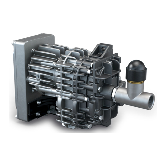
Product Description | 2 Product Description Description 6-pole HDSCS connector (CAN) Electrical connection (+V Batt Suction connection Nameplate Discharge connection Pressure relief valve NOTE Technical term. In this instruction manual, we consider that the term ‘machine’ refers to the ‘compressor’. NOTE Illustrations In this instruction manual the illustrations may differ from the machine appearance. -
Page 6: Operating Principle
Conveying of other media leads to an increased thermal and/or mechanical load on the machine and is permissible only after a consultation with Busch. The machine is intended for the placement in a non-potentially explosive environment. Permitted environmental conditions, see Technical Data [➔ 40]. -
Page 7: Transport
Transport | 3 Transport NOTICE If the machine has a relief valve Risk of damage to the machine! ● Do not handle the machine by the relief valve. ● To find out the weight of the machine, refer to the chapter Technical Data [➔ 40] or the name- plate (NP). -
Page 8: Storage
4 | Storage Storage ● Seal all apertures with adhesive tape or reuse provided caps, if not connected to a system. If the machine is to be stored for more than 2 months: ● Make sure that the inside of the process chamber will be kept dry and dust free at ambient temperature. -
Page 9: Installation
Installation | 5 Installation Installation Conditions NOTICE Use of the machine outside of the permitted installation conditions. Risk of premature failure! Loss of efficiency! ● Take care that the installation conditions are fully complied with. Description Fixing points ● Make sure that the environment of the machine is not potentially explosive. ●... -
Page 10: Connecting Lines / Pipes
Busch representative to discuss the corresponding levels. If the machine is installed at an altitude greater than 1000 meters above sea level: ● Contact your Busch representative, the motor should be derated or the ambient temperature limited. Connecting Lines / Pipes WARNING Unprotected connection. -
Page 11: Suction Connection
Installation | 5 5.2.1 Suction Connection WARNING Unprotected connection. Risk of severe injury! ● Do not put hand or fingers in the connection. NOTICE Ingress of foreign objects or liquids. Risk of damage to the machine! If the inlet gas contains dust or other foreign solid particles: ●... -
Page 12: Electrical Connection
● Make sure that the motor of the machine will not be affected by electric or electro- magnetic dis- turbance from the mains, if necessary seek advice from Busch. ● Make sure that the EMC of the machine is compliant with the requirements of your supply net- work system, if necessary provide further interference suppression (EMC of the machine, see EU Declaration of Conformity [➔ 41] or UK Declaration of Conformity [➔ 42]). -
Page 13: Version With Analog Speed Control
Electrical Connection | 6 ● If the machine is equipped with a power connector, install a residual current protective device to protect persons in case of isolation default. ● If the variable speed drive is not equipped with a lockable disconnect switch, provide it on the power line so that the machine is completely secured during maintenance tasks. -
Page 14: Version With Can-Communication
6 | Electrical Connection Description Version with CAN-Communication NOTE If KL15 cable (pin 1 of the CAN connector) and CAN cable are longer than 30 meters. Risk of electromagnetic disturbances! ● Make sure that the length of each cable does not exceed 30 meters. Description KL15 (20-32VDC) CAN H... -
Page 15: Commissioning
Commissioning | 7 Commissioning NOTICE Lubricating a dry running machine (compression chamber). Risk of damage to the machine! ● Do not lubricate the compression chamber of the machine with oil or grease. CAUTION During operation the surface of the machine may reach temperatures of more than 70°C. Risk of burns! ●... -
Page 16: Standard Version
7 | Commissioning ● Fully open the valve (decrease the spring resistance) by a clockwise rotation. Fully close the bench inlet valve so that fresh air comes in by the relief valve only (volume flow sensor mentions 0 lpm). ● Adjust the relief valve position by closing the valve (increase the spring resistance) by a counter- clockwise rotation to achieve 450 hPa (mbar) absolute +/- 5 hPa. -
Page 17: Version With Can-Communication
Commissioning | 7 Version with CAN-Communication The CAN communication and protocol are based on the following standards: ● ISO 11898 for hardware, ● SAE J1939 as vehicle standard for the software. The CAN address coding is using the Intel protocol with Little Endian format. The machine is controlled via CAN communication (see CAN Protocol [➔ 37]). - Page 18 7 | Commissioning CAN Status Message (Actual Values) One second after startup, the machine sends every 50 ms a CAN status message with actual values. If the machine receives a CAN control message before the first second after startup the machine sends the CAN status message immediately.
- Page 19 Commissioning | 7 Plausibility check A blocked rotor cannot be detected under all conditions by an overcurrent detection. Therefore, an additionally plausibility check is implemented. The plausibility check checks different ratios inside the motor controller. If a plausibility check error occur the motor stops immediately and the bit 5 “plausibility error”...
-
Page 20: Maintenance
Risk of premature failure and loss of efficiency! ● Maintenance work must only be executed by qualified personnel. ● Respect the maintenance intervals or ask your Busch representative for service. ● Shut down the machine and lock against inadvertent start up. -
Page 21: Maintenance Schedule
Maintenance | 8 Maintenance Schedule The maintenance intervals depend very much on the individual operating conditions. The intervals given below are considered as starting values which should be shortened or extended as appropri- ate. Particularly harsh applications or heavy duty operation, such as high dust loads in the environ- ment or in the process gas, other contamination or ingress of process material, can make it neces- sary to shorten the maintenance intervals significantly. -
Page 22: Draining Procedure
Risk of damage to the machine! ● Before proceeding the oil draining, make sure that the cylinder of your machine has four access holes to the motor screws. If not, do not proceed the oil draining and contact your Busch repre- sentative. - Page 23 NOTICE Use of an inappropriate oil. Risk of premature failure! Loss of efficiency! ● Only use an oil type which has previously been approved and recommended by Busch. NOTE Oil draining. Recommendation. ● There is no ideal angle to put the gear for oil draining. We would recommend to move the gear- box several times from standard “vertical position”...
- Page 24 8 | Maintenance As shown in the illustration above: ● 1. Remove the oil filling plug and drain the oil. ● 2-3. With the machine in vertical position, refill with the new oil until the oil level is close to the lower edge of the oil draining/filling hole.
- Page 25 Maintenance | 8 ● Remove the existing O-Ring carefully to avoid damaging the groove. ● Make sure there is no burr on machined surfaces (chamfer, groove, flange surface, etc.). ● Replace the old motor nose O-ring by the new one delivered in the kit. Put grease on it then place it correctly in its groove.
- Page 26 8 | Maintenance Inserting the stage into the motor NOTICE Inserting the stage into the motor. Risk of damage to the machine! ● Take care and make sure not to shock or bump the stage while inserting it into the motor! ●...
-
Page 27: Service Kit And Oil Type
Risk of severe injury! Risk of damage to the machine! ● The replacement of the machine stage must only be executed by technically trained and qualified Busch personnel 8.3.1 Stage Disassembly ● If the cylinder has four holes for direct access to the motor screws, unscrew them using an M5 hexagonal tool and proceed directly to the “Removing the motor”... - Page 28 8 | Maintenance ● If there is any, remove the plumbing (cut the wire) or the blue seal. ● Picture 1: remove the five M6 screws holding the cylinder and remove the cylinder. ● Picture 2: remove the four M6 screws holding the motor. Do not unscrew the 3 other screws! Removing the motor ●...
- Page 29 Maintenance | 8 NOTICE Cleaning the surface. Risk of damage to the machine! ● Do not use any solvant or liquid. Use only clean and dry paper or tissue! ● Remove the existing O-Ring carefully to avoid damaging the groove. ●...
-
Page 30: Stage Replacement Package
8 | Maintenance ● To keep the traceability, report the former serial number in a dedicated file (such as an .xls file for instance) together with the dismounting date. Report as well the new serial number shown on the new identification label, see Stage Replacement Package [➔ 30] 8.3.2 Stage Replacement Package The new stage is delivered with a kit in a plastic bag including a label with Serial Number. -
Page 31: Stage Reassembly
Maintenance | 8 8.3.3 Stage Reassembly ● Place and stabilize the motor to be refurbished on an adapted positioning device. ● Replace the old motor nose O-ring by the new one delivered in the kit. Put grease on it then place it correctly in its groove. Inserting the stage into the motor NOTICE Inserting the stage into the motor. - Page 32 8 | Maintenance ● Insert gently the stage into the motor. Then insert and tighten the four M6 screws with a 5 Nm (+/-10%) screwing torque. 32 | 44 Instruction Manual MINK MB 0018 A_EN_en...
-
Page 33: Stage Testing
Maintenance | 8 8.3.4 Stage Testing Motor start test: 100% of stages are tested at the manufacturing company and performances are stored for traceabil- ity. This test intends to guarantee that the complete blower starts properly. ● Use a stabilized 500 Watts power supply. ●... -
Page 34: Overhaul
● Decontaminate the machine as much as possible and state the contamination status in a ‘Dec- laration of Contamination’. Busch will only accept machines that come with a completely filled in and legally binding signed ‘Declaration of Contamination’ (form downloadable from www.buschvacuum.com). -
Page 35: Decommissioning
Decommissioning | 10 Decommissioning DANGER Live wires. Risk of electrical shock. ● Electrical installation work must only be executed by qualified personnel. CAUTION Hot surface. Risk of burns! ● Prior to any action requiring touching the machine, let the machine cool down first. ●... -
Page 36: Spare Parts
Risk of premature failure! Loss of efficiency! ● The exclusive use of Busch genuine spare parts and consumables is recommended for the correct functioning of the machine and to validate the warranty. Standard spare parts kits are available for this product. -
Page 37: Can Protocol
CAN Protocol | 12 CAN Protocol 12.1 Standard CAN Interface 250 kBit/s Instruction Manual MINK MB 0018 A_EN_en 37 | 44... -
Page 38: Can Interface 500 Kbit/S
12 | CAN Protocol 12.2 CAN Interface 500 kBit/s ● Baudrate 500 kb/s ● Bit length 11 bit ● Behavior at CAN loss: "0" RPM ● Enable signal for electronics activation "Yes" ● Motor behavior when flow request "0" → "Motor waits for signal" ●... - Page 39 CAN Protocol | 12 ● Control message: 0x0C FF A6 4D ● Parameter values: 0x0C FF A8 4D ● Actual values: 0x0C FF A7 C4 ● Acknowledgement: 0x18 FF AB C4 Instruction Manual MINK MB 0018 A_EN_en 39 | 44...
-
Page 40: Technical Data
*permanent usage / **cycle of 6 minutes operation, 4 minutes stop High frequency transient phases (with up and down pressure levels) need to be discussed and vali- dated between customers and Busch on applications themselves. 40 | 44 Instruction Manual MINK MB 0018 A_EN_en... -
Page 41: Eu Declaration Of Conformity
EU Declaration of Conformity This Declaration of Conformity and the CE-markings affixed to the nameplate are valid for the machine within the Busch scope of delivery. This Decla- ration of Conformity is issued under the sole responsibility of the manufacturer. - Page 42 UK Declaration of Conformity This Declaration of Conformity and the UKCA-markings affixed to the nameplate are valid for the machine within the Busch scope of delivery. This Dec- laration of Conformity is issued under the sole responsibility of the manufacturer.
- Page 43 Notes Instruction Manual MINK MB 0018 A_EN_en 43 | 44...
- Page 44 With a network of over 60 companies in more than 40 countries and agencies worldwide, Busch has a global presence. In every country, highly competent local personnel delivers custom-tailored support backed by a global network of expertise. Wherever you are.
Need help?
Do you have a question about the MINK MB 0018 A and is the answer not in the manual?
Questions and answers