Advertisement
Quick Links
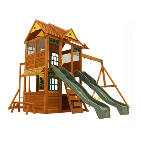
OVERLAND
HEIGHTS
SWING SET
OBSTACLE FREE SAFETY ZONE - 27' 6" x 27' (8.38m x 8.2m) area requires Protective Surfacing. See page 4.
MAXIMUM VERTICAL FALL HEIGHT - 6' 9" (2.06m).
CAPACITY - 12 Users Maximum, Ages 3 to 10; Weight Limit 110 lbs. (50 kg) per child.
RESIDENTAL HOME USE ONLY. Not intended for public areas such as multi-unit residences, schools, churches, nurseries,
day cares or parks.
INSTALLATION AND OPERATING INSTRUCTIONS
FOR 24/7 ONLINE PARTS REPLACEMENT
parts.kidkraft.com
KidKraft, Inc.
4630 Olin Road
Dallas, Texas 75244
USA
customerservice@kidkraft.com
1.800.933.0771
972.385.0100
parts.kidkraft.eu
KidKraft Netherlands BV
Olympisch Stadion 8
1076 DE Amsterdam
The Netherlands
europecustomerservice@kidkraft.com
+31 20 305 8620
M-F from 09:00 to 17:30 (GMT+1)
4.17M
13' 8"
JAZZ
9409655
TWO-PERSON
ASSEMBLY
To reduce the risk of serious injury or death, please read and follow
these instructions. Keep and refer to instructions as needed and
pass along to any future owners of this item.
8.38M
27' 6"
4.72M
15' 6"
Rev 01/12/2022
ASSEMBLY TIME
WARNING. ONLY
FOR OUTDOOR
10 - 14 HOURS
DOMESTIC USE
WARNING
8.23M
27'
Advertisement

Related Manuals for KidKraft OVERLAND HEIGHTS SWING SET


Summary of Contents for KidKraft OVERLAND HEIGHTS SWING SET
- Page 1 13' 8" JAZZ INSTALLATION AND OPERATING INSTRUCTIONS FOR 24/7 ONLINE PARTS REPLACEMENT 9409655 Rev 01/12/2022 parts.kidkraft.com parts.kidkraft.eu KidKraft, Inc. KidKraft Netherlands BV 4630 Olin Road Olympisch Stadion 8 TWO-PERSON ASSEMBLY TIME WARNING. ONLY FOR OUTDOOR ASSEMBLY 10 - 14 HOURS...
- Page 2 Congratulations on purchasing a KidKraft product! Our items are made of high-quality, durable Cunninghamia Lanceolata wood from the cypress family. Lumber from these trees are known for their light weight and excellent strength. The porosity of this wood allows the moisture to absorb and evaporate in the fibers, resisting rot and bugs.
- Page 3 Warnings and Safe Play Instructions CONTINUOUS ADULT SUPERVISION REQUIRED. Most serious injuries and deaths on playground equipment have occurred while children were unsupervised! Our products are designed to meet mandatory and voluntary safety standards. Complying with all warnings and recommendations in these instructions will reduce the risk of serious or fatal injury to children using this play system.
- Page 4 Protective Surfacing - Reducing Risk of Serious Head Injury From Falls One of the most important things you can do to reduce the likelihood of serious head injuries is to install shock-absorbing protective surfacing under and around your play equipment. The protective surfacing should be applied to a depth that is suitable for the equipment height in accordance with ASTM F1292.
- Page 5 Instructions for Proper Maintenance Your KidKraft Play System is designed and constructed of quality materials with your child’s safety in mind. As with all outdoor products used by children, it will weather and wear. To maximize the enjoyment, safety and life of your Play Set, it is important that you, the owner, properly maintain it.
- Page 6 About Our Wood KidKraft Premium Play Systems uses only premium playset lumber, ensuring the safest product for your children’s use. Although we take great care in selecting the best quality lumber available, wood is still a product of nature and susceptible to weathering which can change the appearance of your set.
- Page 7 KidKraft Limited Warranty MISSING OR DAMAGED PARTS: KidKraft will replace any parts within 90 days from date of purchase found to be missing from or damaged in the original packaging. See Fig.1 Fig. 1 Product Age (All Parts) Consumer Pays...
- Page 8 Keys to Assembly Success Tools Required • Tape Measure • #1 Phillips, #2 Robertson • Open End Wrench • 3/16” Hex Key • Carpenters Level and Screwdriver (1/2” & 9/16”) • 8’ Step Ladder • Carpenters Square • Ratchet with extension •...
- Page 9 Part Identification (Next Generation A) Actual Size Nominal Size (1) MK Ground 1 x 4 x 55-1/4" (16 x 86 x 1403mm) ⅜ " x 3 ⅜ " 2" x 4" 0353 2" x 3" ⅜ " x 2½" 3640353 1"...
- Page 10 ADD ON C Parts (Reduced Part Size) 2pc. - 5536 - 5/8 x 2 x 6-3/4" (16 x 51 x 171mm) - Counter Side - 38045536 1pc. - 2686 - 5/8 x 2-3/4 x 40-5/8" (16 x 70 x 1032mm)- Counter Front - 3632686 2pc.
- Page 11 Next Generation C (Actual Part Size) 2pc. TN1 - 1/4" (6mm) T - Nut (54503200) Hex Bolt 1/4 x 2-3/4" (6 x 70mm) 2pc. H11 - (53703223) 2pc. FW1 - 1/4" (6mm) Flat Washer (51103200) 2pc. LW1 - 1/4" (6mm) Lock Washer (51303200) #6 x 30mm 20pc.
- Page 12 Part Identification (Add on E) 2pc. - 2756 Siding Assembly 1¼ x 19-15/16 x 39-3/16" (32 x 506 x 995mm) 37632756 1pc. - 2658 - 2-13/32 x 6-3/4 x 34" (61 x 171 x 864mm) Folding Bench 37632658 2pc. - 649A Short Half Wall - 1.27 x 18.8 x 20-15/16"...
- Page 13 Add On D Hardware (Actual Size) 36pc. TN1 - 1/4" (6mm) T - Nut 5pc. FW0 - 3/16" (5mm) Flat Washer - (54503200) (51103100) 9pc. LW2 - 5/16" (8mm) Lock Washer - (51303300) 42pc. FW1 - 1/4"(6mm) Flat Washer - 10pc.
- Page 14 Add On D Hardware (Actual Size) Wafer Bolt 5/16 x 1" Wafer Bolt 5/16 x 3" (8 x 76mm) 2pc. WB1 - - (53613310) 3pc. WB7 - - (53613330) (8 x 25mm) Hex Bolt 1/4 x 1-1/4" 24pc. H9 - - (53703211) 1/4 x 1-3/8"...
- Page 15 Part Identification (Add on E) 1pc. - 2757 1pc. - 2648 - 1 x 4 x 40-5/8 (16 x 86 x 1032mm )- Floor Board 3632648 LT Post Assembly 1¼ x 2½ x 87" (32 x 64 x 2210mm ) 8pc.
- Page 16 Part Identification (Next Generation F) 4pc. - 2759 Roof End 1-1/4 x 3 x 10" (32 x 76 x 254mm) 3632759 4pc. - 2760 - Roof Support 1¼ x 2¼ x 37½" (32 x 57 x 953mm ) 3632760 2pc. - 2761 - Roof Sleeper C ¾ x 2 x 35" (19 x 51 x 889mm ) 2x - Sky Gable (3320212) 3632761 2pc.
- Page 17 If there are any missing or damaged pieces or you need assistance with assembly please contact the consumer relations department directly. Call us before going back to the store. 1.800.933.0771 or 972.385.0100 +31 20 305 8620 europecustomerservice@KidKraft.com customerservice@kidkraft.com For online parts replacement visit canadacustomerservice@kidkraft.com https://parts.kidkraft.eu/ For online parts replacement visit https://parts.kidkraft.com/...
- Page 18 Step 1: Front and Back Wall Prep Part 1 It is important to assemble the frame on a flat, smooth surface. A: Place (2771) End Post and (2770) End Post Left side by side with the grooves facing up and in. Put (2770) End Post Left on the right hand side.
- Page 19 Step 1: Front and Back Wall Prep Part 2 It is important to assemble the frame on a flat, smooth surface. D: Turn the assembly over, place (2774) Upright in the middle groves of (2775) Panel Cross Support and (2772) Panel Floor Support then attach all boards with 8 (H9) Hex Bolts (with lock washer and flat washer) connecting to the previously installed t-nuts.
- Page 20 Step 2: End Wall Prep Part 1 It is important to assemble the frame on a flat, smooth surface. A: Place (2768) Panel Floor and 2 (2769) Panel BT Frames on a hard, flat surface with the long side up. Tap in 2 (TN1) T-nuts per board.
- Page 21 Step 2: End Wall Prep Part 2 It is important to assemble the frame on a flat, smooth surface. D: Turn the assembly over then attach all boards with 6 (H9) Hex Bolts (with lock washer and flat washer) connecting to the previously installed t-nuts. (fig. 2.3 and 2.4) Fig.
- Page 22 Step 3: Swing Wall Prep Part 1 It is important to assemble the frame on a flat, smooth surface. A: Place (2757) LT Post Assembly and (2758) RT Post Assembly on a hard, flat surface with the notches facing down. The top of the post assemblies have the longer notches. (fig. 3.1) B: Tap 1 (TN2) T-nut in the top holes and 1 (TN1) T-nut in the middle and bottom holes.
- Page 23 Step 3: Swing Wall Prep Part 2 It is important to assemble the frame on a flat, smooth surface. C: Turn the (2757) LT Post Assembly and (2758) RT Post Assembly over and place 2 (2756) Siding Assemblies on top so one sits flush with the top of the middle groove and the second fits flush with the top of the bottom groove.
-
Page 24: Table Of Contents
Step 3: Swing Wall Prep Part 3 It is important to assemble the frame on a flat, smooth surface. E: Attach (2630) SW Top to (2757) LT Post Assembly and (2758) RT Post Assembly with 2 (WB1) Wafer Bolts (with flat washer) connecting to previously installed t-nuts. (fig. 3.5 and 3.6) F: Attach (2768) Panel Floor to (2757) LT Post Assembly and (2758) RT Post Assembly with 2 (H9) Hex Bolts (with lock washer and flat washer) connecting to previously installed t-nuts. -
Page 25: Fig. 3.8
Step 3: Swing Wall Prep Part 4 It is important to assemble the frame on a flat, smooth surface. I: Attach the top board in each (2756) Siding Assembly to (2757) LT Post Assembly and (2758) RT Post Assembly with 4 (S30) Wood Screws per board. (fig. 3.8 and 3.9) J: Attach the remaining boards in each (2756) Siding Assembly to (2757) LT Post Assembly and (2758) RT Post Assembly with 2 (S0) Truss Screws per board. -
Page 26: Fig. 4.1
Step 4: Frame Assembly Part 1 It is important to assemble the frame on a flat, smooth surface. A: Place Swing Wall from Step 3 between 2 Front and Back Walls from Step 1, noticing the wall orientations. The tops and bottoms of the walls should be flush. Make sure the walls are square then using the pilot holes as a guide pre-drill with a 3/16”... -
Page 27: Wood Parts
Step 4: Frame Assembly Part 2 B: Place End Wall between 2 (2677) Narrow Panels noticing the panel orientations. The tops and bottoms of the panels should be flush. Make sure the panels are square then using the pilot holes as a guide pre-drill with a 3/16”... - Page 28 Step 4: Frame Assembly Part 3 C: With at least two helpers lift the two wall assemblies so the Front and Back Walls meet and are tight to the (2677) Narrow Panels as shown in fig. 4.7. D: Make sure the assembly is square then on the inside of the assembly, tight to (2769) Panel BT Frame on the End Wall and flush to the bottom attach 1 (2608) Floor Joist to (2677) Narrow Panel and (2769) Panel BT Frame on the front and back walls with 4 (S11) Wood Screws per board.
- Page 29 Step 4: Frame Assembly Part 4 Tight Swing Wall Fig. 4.9 E: On the Back Wall, from inside the assembly, tight to the End Wall, halfway up Top View 2777 the assembly, 5/8” (15.9 mm) down from the top of the panel board attach 1 (2777) Side 2682 Joist MOD to (2677) Narrow Panel and (2772) Panel Floor Support with 2 (H11) Hex Bolts...
- Page 30 Step 4: Frame Assembly Part 5 H: From inside the assembly, flush to the top of the assembly attach 1 (2683) Wall Tie to (2677) Narrow Panel and (2775) Panel Cross Support on both the front and back walls with 5 (S11) Wood Screws per board. (fig. 4.11) Fig.
- Page 31 Step 4: Frame Assembly Part 6 I: On the inside of the assembly attach (2677) Narrow Panel to the Front and Back Walls using 2 Flat Panel Brackets per wall in the places shown with 4 (S8) Pan Screws per bracket. (fig. 4.12 and 4.13) Fig.
-
Page 32: X 2607 Diagonal
Step 4: Frame Assembly Part 7 J: Loosely attach 1 (2607) Diagonal to left (2778) SW Ground MOD with 1 (H10) Hex Bolt (with lock washer, flat washer and t-nut). (fig. 4.14) K: Place each (2607) Diagonal tight and flush to the front of the Swing Wall then pre-drill pilot holes with a 3/16” (4.8 mm) drill bit and attach each (2607) Diagonal to the Swing Wall with 1 (LS3) Lag Screw (with flat washer) per board, checking that they remain flush to outside edge. - Page 33 Step 5: Floor Assembly Part 1 A: From inside of the assembly centre (2681) Long Floor Joist over pilot holes in both (2768) Panel Floors in the Swing and End Walls, measure 5/8” (15.9 mm) down from the top of boards then attach (2681) Long Floor Joist to each board with 2 (S4) Wood Screws per end.
- Page 34 Step 5: Floor Assembly Part 2 B: Starting at the Swing Wall place 4 (2609) Floor Boards followed by 1 (2648) Floor Board then the remaining 9 (2609) Floor Boards. Make sure all boards are evenly spaced then attach to (2681) Long Floor Joist and each (2777) Side Joist MOD and (2682) Short Side Joist with 5 (S20) Wood Screws per board.
- Page 35 Step 6: Swing Beam Assembly A: Attach 6 Swing Hangers to the (2614) Engineered Beam using 2 (G7) Hex Bolts (with 2 flat washers and 1 lock nut) per Swing Hanger as shown in fig. 6.1. B: Flush to the Fort End of (2614) Engineered Beam attach 2 L-Beam Brackets with 2 (G21) Hex Bolts (with 2 flat washers and 1 lock nut).
- Page 36 Step 7: Swing End Assembly A: Loosely attach 2 (2613) Heavy SW Posts to (2615) SW Upright using 2 (G7) Hex Bolts (with lock washer, flat washer and t-nut). Notice 2 bolt holes at top of (2615) SW Upright and orientation of angle. (fig. 7.1) B: Attach (2616) SW Support to both (2613) Heavy SW Posts and (2615) SW Upright using 3 (G4) Hex Bolts (with lock washer, flat washer and t-nut).
- Page 37 Step 8: Attach Swing End to Swing Beam A: Place Swing End Assembly against Swing Beam Assembly then place 1 Beam Bracket on each side of the assembly (they are specific for left and right side) and attach with 5 (G21) Hex Bolts (with 2 flat washers and 1 lock nut).
- Page 38 Step 9: Attach Swing Assembly To Fort A: Place Swing Assembly against top of (2630) SW Top, make sure assembly is level then attach from inside the fort assembly into each L-Beam Bracket with 4 (G8) Hex Bolts (with 2 flat washers and 1 lock nut). (fig. 9.1) L-Beam 2630...
- Page 39 Step 10: Install Ground Stakes MOVE FORT TO FINAL LOCATION PRIOR TO STAKING FINAL LOCATION MUST BE LEVEL GROUND A: In the 5 places shown in fig. 10.1 drive the Rebar Ground Stakes 13” (330 mm) into the ground against outside front corner of the End Wall, on both (2607) Diagonals and both (2613) Heavy SW Posts.
- Page 40 Step 11: How to Install Inserts - Upper and Lower Jambs There is 1 (2601) Lower Jamb and 1 (2602) Upper Jamb provided. Install the (2601) Lower Jamb on the Back Wall and the (2602) Upper Jamb on the End Wall using 2 Jamb Mounts and 8 (S0) Truss Screws per board. Use the diagrams below to show correct placement of each board.
- Page 41 Step 12: How to Install Inserts - Window and Wall Inserts Part 1 There are 2 (2649) Lower Window Inserts, 2 (2655) Upper Window Inserts, 1 (2665) Half Wall Insert, 4 (649A) Short Half Walls and 2 MOD 3-Pane Transoms provided. Use the Jazz Fort Guide to see where each insert is installed.
- Page 42 Step 12: How to Install Inserts - Window and Wall Inserts Part 2 Inside Views 3-Pane Transom Tight 649A 2665 Tight Tight REV. DWG. NO. SCALE:1:50 SHEET 2 OF 2...
- Page 43 Step 13: How to Install Inserts - Clock Assembly There is 1 Clock Set provided to be installed on the Back Wall. See Jazz Fort Guide for correct location. See below for how to assemble and attach the Clock Set. When installing you will need the following: Base Clock, Clock Subset (includes minute and hour hands, clock adapter and clock screw), 2 (2717) Clock Blocks and 4 x (S20) Wood Screws.
- Page 44 Step 14: Rock Wall Assembly Fig. 14.1 Note: The holes in the rock boards 2776 must orient to the 2780 2780 2781 top of the boards. 2781 2781 2779 7-5/8” (193.6 mm) x 4 per Approx board Note: Gaps between boards 2-1/4” (57 mm), not to exceed 2-3/8”...
- Page 45 Step 15: Attach Rock Wall Assembly to Fort Part 1 A: Place Rock Wall Assembly centred in opening of the Front Wall as shown in the Jazz Fort Guide and flush as shown below. Attach (2776) Rock Rails to the Front Wall using 4 (S11) Wood Screws. (fig. 15.1 and 15.2) B: Attach 1 (2779) Access Board to top of Rock Wall Assembly, flush to top of (2776) Rock Rails using 4 (S2) Wood Screws.
- Page 46 Step 15: Attach Rock Wall Assembly to Fort Part 2 C: Drive 1 Rebar Ground Stake 13” (330 mm) into the ground against outside (2776) Rock Rail then attach with 1 (S7) Pan Screw. Be careful not to hit the washer while hammering stake into the ground as this could cause the washer to break off.
- Page 47 Step 16: Attach Hand Grip to Fort A: Measure 6” (152.4 mm) from the top of the floor boards on the left hand side of the Rock Board, pre-drill with a 1/8” (3.2 mm) drill bit then attach 1 Play Handle with 2 (WL3) Wafer Lags to the Front Wall. (fig. 16.1) Play Handle Fig.
- Page 48 Step 17: Cafe Table Assembly A: Place (2612) Table Support flush to the notched out ends of (2611) Table Top and attach with 4 (S7) Pan Screws as shown in fig. 17.1. B: Place Table Top Assembly tight in the opening of End Wall with the overhang on the outside of the assembly as shown in fig.
- Page 49 Step 18: Attach Cafe Canopy to Fort A: Feed Cafe Canopy Frame through the pocket of the Cafe Canopy. (fig. 18.1) B: With a helper hold the Canopy against the fort, on the End Wall as shown on the Jazz Fort Guide, measure 3-1/8”...
- Page 50 Step 19: Attach Sky Chalk Wall to Fort A: From inside the assembly place Sky Chalk Wall tight to (2611) Table Top and (2772) Panel Floor Support then attach with 4 (S10) Pan Screws from the inside and 1 (S10) Pan Screw from the outside. (fig. 19.1, 19.2, 19.3 and 19.4) Fig.
- Page 51 Step 20: Roof Support Assembly A: Attach 1 (2760) Roof Support to a second (2760) Roof Support at peak using 1 (S4) Wood Screw. Repeat this step so there are 2 Roof Support Assemblies. (fig. 20.1 and 20.2) Fig. 20.1 Roof Support Assembly 2760...
- Page 52 Step 21: Roof Panel Assembly A: Place 1 (2751) MOD Roof Bottom tight to the bottom of (2752) MOD Roof Front and (2753) MOD Roof Back. (fig. 21.1) B: Place a (2761) Roof Sleeper C on the middle strip of each Roof Panel Assembly so the ends are flush and attach with 4 (S20) Wood Screws per panel.
- Page 53 Step 22: Roof Assembly Part 1 A: Place Front Roof Panel against Back Roof Panel so the tops form a peak then tight to the inside edge of the outside slats attach 1 Narrow Angle Bracket per slat with 2 (S0) Truss Screws per bracket. (fig. 22.1 and 22.2) B: Attach the third Narrow Angle Bracket centred on the middle slat with 2 (S0) Truss Screws.
- Page 54 Step 22: Roof Assembly Part 2 C: Place 1 Roof Support Assembly against one side so the peaks meet and the ends of the roof supports are flush with the ends of the roof panels. Attach with 8 (S11) Wood Screws. (fig. 22.4) D: Attach the second Roof Support Assembly on the opposite side, peaks to meet and ends are flush with 8 (S11) Wood Screws.
- Page 55 Step 23: Attach Sky Gable A: Attach 1 Sky Gable to the inside of the (2760) Roof Supports on one side of the Roof Assembly with 4 (S5) Pan Screws. (fig. 23.1 and 23.2) Fig. 23.1 Roof Assembly Sky Gable 2760 Fig.
- Page 56 Step 24: Small Roof Assembly Part 1 A: Attach 1 (2680) Roof Support to a second (2680) Roof Support at peak using 1 (S4) Wood Screw. (fig. 24.1) Fig. 24.1 2680 Wood Parts Hardware Wood Screw Roof Support 2680...
- Page 57 Step 24: Small Roof Assembly Part 2 B: Place (2672) Front Small Roof against (2671) Back Small Roof so the tops form a peak then tight to the inside edge of the outside slats attach 1 Narrow Angle Bracket per slat with 2 (S0) Truss Screws per bracket. (fig.
- Page 58 Step 25: Gable Dormer Assembly A: Place (2699) Gable Dormer RT tight to (2689) Gable Dormer LT then place Sky Gable tight against the dormers and attach with 4 (S5) Pan Screws. (fig. 25.1) B: Attach (2699) Gable Dormer RT and (2689) Gable Dormer LT with 1 Narrow Angle Bracket using 2 (S5) Pan Screws.
- Page 59 Step 26: Attach Gable Dormer to Roof A: On the outside of the Large Roof Assembly on front of the Roof, on the 5th siding down, place (2688) Dormer Cleat centred on the panel (over the middle inside slat) then attach with 2 (S11) Wood Screws. Make sure the screws go into the siding and the slats.
- Page 60 Step 27: Attach Roof Ends Part 1 A: On the End Wall remove the 2 outside (H9) Hex Bolts attached at the top of the assembly from Step 2, Part 2. Leave the (TN1) T-nuts in. The (FW1) Flat Washers and (LW1) Lock Washers will be used in Step B. (fig. 27.1) Fig.
- Page 61 Step 27: Attach Roof Ends Part 2 B: Loosely attach 1 (2759) Roof End to each corner of the End Wall, flush to the top of (2769) Panel BT Frame, with 1 (H3) Hex Bolt per board, using the (FW1) Flat Washer and (LW1) Lock Washer from Step A and connecting to the (TN1) T-nut.
- Page 62 Step 27: Attach Roof Ends Part 3 C: Measure overhang so it is 4-7/8” (124 mm) then attach with 2 (S11) Wood Screws and 1 (S3) Wood Screw per (2759) Roof End. Tighten the bolts. (fig. 27.6, 27.7 and 27.8) Fig.
- Page 63 Step 27: Attach Roof Ends Part 4 D: Attach 1 (2759) Roof End to each corner of the Swing Wall, flush to the top of (2630) SW Top and overhanging 4-7/8” (124 mm) then attach with 2 (S11) Wood Screws and 1 (S3) Wood Screw per (2759) Roof End.
- Page 64 Step 27: Attach Roof Ends Part 5 E: On the Back of the fort measure 21-5/8” (549 mm) from (2759) Roof End and 1-1/4” (32 mm) down from the top of (2677) Narrow Panel, pre-drill with a 3/16” (4.8 mm) drill bit then place 1 (2684) Mid Roof End centred over the pilot hole and flush to the top of (2677) Narrow Panel attach from the inside with 1 (S4) Wood Screw and from the outside with 1 (S3) Wood Screws.
- Page 65 Step 28: Attach Roof Assemblies to Fort Part 1 A: With 2 people on the ground and at least 1 person in the fort, lift the Large Roof Assembly up and over the Back side of the fort. Guide the Roof Assembly onto the fort so all four (2760) Roof Supports sit flush to the front and outside edges of (2759) Roof End and (2684) Mid Roof End.
- Page 66 Step 28: Attach Roof Assemblies to Fort Part 2 C: Place (9450) Roof Tie so that the angled end is flush against (2761) Roof Sleeper C and the other end is flat against (2683) Wall Tie, centered between the Hex Bolts. Attach using 3 (S11) #8 x 2” Wood Screws, making sure that the top 2 screws are installed on an angle as shown in fig.
- Page 67 Step 28: Attach Roof Assemblies to Fort Part 3 E: With 2 people on the ground and at least 1 person in the fort, lift the Small Roof Assembly up and over the Back side of the fort. Guide the Small Roof Assembly onto the fort so it slides under the Large Roof Assembly and the (2760) Roof Supports sit tight to the siding on the Small Roof Assembly.
- Page 68 Step 28: Attach Roof Assemblies to Fort Part 4 G: Attach (2760) Roof Supports to both (2684) Mid Roof Ends with 1 (S3) Wood Screw per support. (fig. 28.5 and 28.6) H: Attach (2680) Roof Supports to both (2759) Roof Ends with 1 (S3) Wood Screw per support. (fig. 28.5 and 28.6) 2760 2680...
- Page 69 Step 29: Counter Assembly Part 1 A: Flush to each end and to the top of (2687) Counter Back attach 1 (5736) Counter Joist per end with 1 (S2) Wood Screw per joist. Notice the remaining holes at the bottom of (2687) Counter Back. (fig. 29.1) B: Place the remaining 2 (5736) Counter Joists centred over the pilot holes in the middle of (2687) Counter Back and flush to the top of the board, then attach, in the top holes, with 1 (S2) Wood Screw per joist.
- Page 70 Step 29: Counter Assembly Part 2 C: On the inside of the Swing Wall place Counter Assembly so the top of (2687) Counter Back is flush to the top of the opening then attach with 5 (S2) Wood Screws. (fig. 29.2 and 29.3) Back Fig.
- Page 71 Step 29: Counter Assembly Part 3 D: Place 1 (6136) Counter Brace flush to the front and outside edge of each outer (5736) Counter Joist and tight to the Swing Wall then attach with 2 (S3) Wood Screws per brace. (fig. 29.4 and 29.5) Fig.
- Page 72 Step 29: Counter Assembly Part 4 E: Place (2686) Counter Front against (5736) Counter Joists so the ends are flush and the centre (5736) Counter Joists are centred over the pilot holes. Measure 5/8” (15.9 mm) down from the top of (2686) Counter Front on both ends and attach to the (5736) Counter Joists with 4 (S2) Wood Screws.
- Page 73 Step 29: Counter Assembly Part 5 F: Tight to (2687) Counter Back attach (2685) Counter Top to each (5736) Counter Joist with 4 (TS) Trim Screws. (fig. 29.7) G: Tight to (2685) Counter Top and flush to the outside edges of the outer (5736) Counter Joists attach 1 (5536) Counter Side per joist with 3 (TS) Trim Screws per board.
- Page 74 Step 29: Counter Assembly Part 6 J: Place Faucet and 2 Sink Knobs in opening of Sink and attach Sink Knobs with included hardware. (fig. 29.9) Important: Use a hand held screw driver and DO NOT over tighten. Fig. 29.9 Faucet Sink Knob Sink Knob...
- Page 75 Step 29: Counter Assembly Part 7 K: Place Sink and Stove in the openings of the Counter Assembly then attach 4 Mount Clips with included hardware to the bottom of the Sink and Stove to secure in place. (fig. 29.10 and 29.11) Important: Use a hand held screw driver and DO NOT over tighten.
- Page 76 Step 30: Attach Utensil Shelf A: From inside the assembly, centred in the top of the opening of the Swing Wall above the counter attach Utensil Shelf with 2 (S5) Pan Screws as shown in fig. 30.1 and 30.2. B: Attach Pot, Pan and Spatula to the Utensil Shelf. (fig. 30.1) Fig.
- Page 77 Step 31: Attach Slides to Fort A: Place 1 Slide in the centre of each opening at the front of the fort as shown in the Jazz Fort Guide, pre-drill with a 1/8” (3.2 mm) drill bit then attach each slide to fort through the (2772) Panel Floor Support using 3 (S7) Pan Screws per slide.
- Page 78 Step 32: Attach Flags A: On the front side of the Swing Wall measure 4” down from the bottom of (2759) Roof End and 2” in from the Front Wall then attach 1 Flag with 2 (S10) Pan Screws per flag. (fig. 32.1) B: On the front side of the End Wall measure 4”...
- Page 79 Step 33: Attach Belt Swings and Glider A: Attach 1 Threaded Clip to each Acro Rope EN71 and the Acro Bar. Attach another Threaded Clip to each Acro Handle and join with first Threaded Clip. Make sure to close the Threaded Clip tightly using an adjustable wrench.
- Page 80 Step 34: Monkey Rail Assembly Pre-drill all pilot holes using a 1/8” (3.2 mm) drill bit before installing Wood Screws. A: Insert 3 (578) Dowels into both (1564) MK Rail Longs as shown in fig. 34.1. Note the pilot holes in one of the (1564) MK Rail Long are on the bottom of the board.
- Page 81 Step 35: Monkey Ladder Assembly A: Insert 1 (858) Dowel into 2 (1367) Post MK as shown in fig. 35.1. Fig. 35.1 1367 Fig. 35.2 B: Make sure shoulder of dowel is against each post before pre-drilling pilot holes. Drill 1/8” (3.2 mm) pilot holes through the posts and into the dowel to prevent splitting.
- Page 82 Step 36: Connect Monkey Bar Assemblies Note: Pre-drill all holes using a 1/8” (3.2 mm) drill bit before installing the pan screws. A: Using a Monkey Bracket connect (1564) MK Rail Longs to each (1367) Post MK with 1 (G10) Hex Bolt (with lock washer, flat washer and t-nut) per bracket and Monkey Bracket to the rails using 2 (S6) Pan Screws per rail as shown in fig.
- Page 83 Step 37: Connect Monkey Bar Assembly to Fort Pre-drill all pilot holes using a 1/8” (3.2 mm) drill bit before installing the lag screws. A: In the opening of the Back Wall measure 18” (457 mm) from the bottom of the opening on both sides then with a MB Mount Strap attach both (1564) MK Rail Longs to (2771) End Post and (2774) Upright using 1 (LS3) Lag Screw (with flat washer) in the centre hole and 2 (S6) Pan Screws in the 2 end holes per bracket as shown in fig.
- Page 84 Step 38: Attach Monkey Ladder Ground Stake A: Drive 1 Rebar Ground Stake 13” (330 mm) into the ground against (1367) Post MK then attach with 1 (S7) Pan Screw. Be careful not to hit the washer while hammering stake into the ground as this could cause the washer to break off.
- Page 85 Step 39: Bench Assembly A: Open the (2658) Folding Bench Assembly. (fig. 39.1, 39.2 and 39.3) B: Make sure assembly is level then secure with 2 (H1) Hex Bolts (with lock washer, flat washer and t-nut) per side. (fig. 39.4) C: Tighten the top screws in all 4 Bench Legs.
- Page 86 Step 40: Attach Window Mesh - Large Part 1 A: From inside the assembly place the Window Mesh - Large over the upper opening in the Swing Wall, make sure the mesh is smooth and tight then attach all four corners to (2757) LT Post Assembly and (2758) RT Post Assembly with 4 (S5) Pan Screws (with #8 flat washers).
- Page 87 Step 40: Attach Window Mesh - Large Part 2 B: Along each side measure 4-1/2” (114 mm) down from the top screws and the same dimension up from the bottom screws then attach 2 (S5) Pan Screws (with #8 flat washer) per side to (2757) LT Post Assembly and (2758) RT Post Assembly.
- Page 88 Step 41: Attach Window Mesh - Small A: From inside the assembly place one Window Mesh - Small over both upper openings in the End Wall, make sure the mesh is smooth and tight then attach all four corners with 4 (S5) Pan Screws (with #8 flat washers) per mesh.
- Page 89 Step 42: Final Step A: Inspect entire play centre and insert hole plugs into all unused holes. See fig. 42.1 and 42.2 for an example. B: Check entire play centre for bolts protruding beyond t-nuts. Use extra Washers to eliminate this condition. Fig.
- Page 90 Fort Guide: Overland Heights Swing Set Flag & Pole (Step 4) 2677 Front MOD 3-Pane Hand Wall Transom Grip (Step 1) Rock Wall Assembly Slide (Step 32) Flag & Pole Flag & Pole MOD 3-Pane (Step 32) Transom (Step 12)
- Page 91 (Step 1) Back Wall Fort Guide: Overland Heights Swing Set (Step 4) 2677 2655 Monkey Ladder 2601 (Step 4) (Step 12) 2677 2655 Clock Clock 649A (Step 13) 2649 649A Monkey Ladder Position (Step 34 -38) 2601 (Step 11) Back Wall...
- Page 92 Would you recommend the purchase of our products to friends and family? Comments: MAIL TO: Fill out your registration card online at KidKraft https://prdregistration.kidkraft.com/ 4630 Olin Road Dallas, TX 75244 Unites States KidKraft would like to say Thank You for Attention: Customer Service your time and feedback.
Need help?
Do you have a question about the OVERLAND HEIGHTS SWING SET and is the answer not in the manual?
Questions and answers