MSA PrimaX IR Operating Manual
Infrared gas monitor
Hide thumbs
Also See for PrimaX IR:
- Quick start manual (2 pages) ,
- Operating manual (44 pages) ,
- Quick start manual (22 pages)

Subscribe to Our Youtube Channel
Related Manuals for MSA PrimaX IR


Summary of Contents for MSA PrimaX IR
- Page 1 Operating Manual PrimaX® IR Infrared Gas Monitor Order No.: 10113581/05 Print Spec: 10000005389 (EO) CR: 800000052040 MSAsafety.com...
- Page 2 The warranties made by MSA with respect to the product are voided if the product is not installed and used in accordance with the instructions in this manual. Please protect yourself and your employees by following the instructions.
-
Page 3: Table Of Contents
Sunshield Duct Mount Kit HART Module Insect Guard/Remote Calibration Inserts Approvals PrimaX IR ATEX/IECEx Approval Information PrimaX IR cFMus Approval Information Prima X IR Calibration Cap Special conditions for the safe use according to ATEX and SIL applications PrimaX® IR... -
Page 4: Safety Regulations
Safety Regulations Correct Use The PrimaX IR Gas Monitor - referred to hereafter as device - is a fixed infrared combustible gas detector. It is suitable for outdoor and indoor applications, e.g. offshore industry, chemical and petrochemical industry, water and sewage industry. -
Page 5: Safety And Precautionary Measures To Be Adopted
MSA service provider, could cause the product to fail to perform as designed. • There are no field-repairable internal components for this device. Return to MSA for warranty replacement per the Warranty section. - Page 6 1 Safety Regulations The Seller shall be released from all obligations under this warranty in the event repairs or modifications are made by persons other than its own or authorized service personnel or if the warranty claim results from physical abuse or misuse of the product.
-
Page 7: Description
4-20 mA output signal. Other detailed device status is available via the HART signal. Details about this interface can be found in the PrimaX IR HART Specification located on the product CD shipped with the device. The optional calibration cap provides an LCD display for easy and intuitive calibration of the device. The proper usage of this calibration cap is described in chapter 4.2... - Page 8 Accessories to be used with this product may be packaged separately. Check the enclosed shipping papers to identify all PrimaX IR accessories that have been ordered. Accessories available for the PrimaX IR Gas Monitor include: • Optional junction box equipped with a terminal strip for easy wiring •...
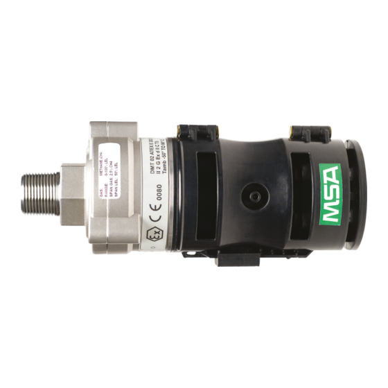
- Page 9 2 Description • Optional HART Calibration cover/Bump cap • Optional Remote HART Calibration kit The complete list of accessories is provided in chapter The device will be labeled with the information shown below: • Target gas, calibration gas and span value •...
-
Page 10: Installation
If a junction box is not being used, mount the device on a support by using suitable hardware (not supplied), and in accordance with local regulatory requirements. MSA recommends mounting the sensor horizontally. Horizontal mounting will help prevent the build-up of particulate or liquid matter on the monitor's optical surfaces. - Page 11 Failure to follow this caution can result in minor or moderate injury. MSA recommends that the device’s environmental guard should be installed on the unit at all times. If the device is to be operated without the guard, frequent checks must be made to ensure particulate or liquid matter has not collected on the windows.
- Page 12 3 Installation A stainless steel mounting plate is included with either junction box to ensure that there is sufficient clearance from the installed surface (see Figure 5 and Figure 6 1. Install the mounting bracket and junction box using the bracket holes as the drilling template. Figure 5 Mounting bracket for Aluminum Junction Box PrimaX®...
-
Page 13: Electrical Installation
3 Installation Figure 6 Mounting bracket for Stainless Steel Junction Box 2. If not using an MSA supplied junction box, refer to Figure 2 or the dimensional drawing to ensure that there is adequate clearance. Ensure that the environmental guard can be easily removed and re-installed. - Page 14 3 Installation Wire Size vs Distance Power Supply Voltage 1.0 mm (18 AWG) 1.5 mm (14 AWG) Signal Load (including termination) 24 Volts 480 m (1575 ft) 720 m (2362 ft) With HART 250 ≤ load ≤ 500 Ω Without HART load ≤ 500 Ω Proper installation should prevent water and dirt from entering the unit via the wires or conduit.
- Page 15 The device can be connected to any device capable of accepting a 4 - 20 mA sourcing analog signal. For FM approved systems, the connecting device must have latching alarms with manual reset. Ensure that your controller can read all signals. Check the MSA website www.MSAsafety.com for available controllers.
-
Page 16: Start-Up And Calibration
Transient Fault conditions will be automatically cleared when the unit recovers from the fault condition. MSA recommends verifying proper response to changes in mA outputs by using the "Enter Fixed Current Mode" command described in the PrimaX IR Link Help Guide to check the four fault conditions noted with a * above. These checks should be done at every calibration phase. -
Page 17: Primax Ir Calibration
The device can be calibrated using either the optional calibration cap locally at the sensor, or using the HART digital interface. MSA recommends using a calibration gas value in the middle of the measuring range for optimum calibration. Calibration methods... - Page 18 4 Start-up and Calibration Figure 8 MSA Calibration Cap Figure 9 Remote HART Hand-held Figure 10 HART Calibration Cover/Bump Cap Alternate Span Gas Settings To achieve the most accurate calibration it is always best to use the gas of interest and calibrate at the operating temperature.
- Page 19 4 Start-up and Calibration The user may change the gas monitor's span value, gas name and gas curve through use of the PrimaX IR Link software found on the product CD. Please refer to the PrimaX IR HART Specification and the PrimaX IR Link Help Guide on the product CD.
- Page 20 IEC/UL/EN 80079-20-1 was used as bases for converting test and calibration gas concentrations from % LEL to % volume fraction For the measurement of n-Pentane, n-Hexane, Propylene, Ethane or Isobutane PrimaX IR shall be calibrated with the target gas at a span value of approximately 50% LEL.
- Page 21 If the Zero calibration fails, remove the calibration cap and reinstall to start another zero attempt. If multiple failures occur, contact an authorized MSA service center. 9. When the display flashes the span gas symbol, apply the span gas through the calibration cap port (see Fig. Figure 8...
- Page 22 4 Start-up and Calibration The unit must see gas within 30 seconds after the span symbol starts to flash or a calibration fault may occur. The initial 30 seconds are intended to give the user time to apply gas to the sensor. During this time, the user can abort the Span process by removing the calibration cap.
- Page 23 4 Start-up and Calibration Steps 5-11 are shown in the figure below: Figure 15 Calibration Cap Sequence of Events PrimaX® IR...
- Page 24 This hand-held HART communicator must be HART revision 7.0 compliant and can be obtained from a HART authorised supplier. See the PrimaX IR HART specification found on the product CD for the calibration command definitions or visit the MSA website at www.MSAsafety.com.
-
Page 25: Calibration Kits
ALWAYS be removed. Failure to follow this warning can result in serious personal injury or death. For applications where access to the HART signal is needed in hazardous areas, MSA provides the HART Module as shown in... - Page 26 4 Start-up and Calibration GAS TYPE CAL CYLINDER CYLINDER P/N CAL KIT # Methane 2.5% Methane 10028032 Propane 0.6% Propane 10028034 Zero Gas 100% Nitrogen 10028030 See the PrimaX IR section of www.MSAsafety.com for additional PrimaX IR calibration gases. PrimaX® IR...
-
Page 27: Maintenance
There are NO field repairable internal components for this device. Do not attempt to open the enclosure of the device, it is factory sealed for protection from hazardous environments. If the troubleshooting guides in chapters not alleviate the problem, contact your MSA representative. Troubleshooting The 4-20 mA output provides a limited set of information for diagnostic purposes. -
Page 28: Hart Information For Troubleshooting
All available status bytes are defined in the PrimaX IR HART Specification found on the product CD. Refer to this document for complete HART command and status definitions. Use the HART digital interface to query the unit to provide additional troubleshooting information. - Page 29 5 Maintenance 2. Place an opaque object (piece of paper, two fingers, etc.) between the light source window and the mirror to completely obscure the light path for two to three seconds (see Figure 20 If the opaque object is left in the light path for longer than 10 seconds, an Obscuration fault will be set on the mA output (see chapter The device enters the Cleaning Mode for 5 minutes.
-
Page 30: Environmental Guard Cleaning
5 Maintenance CAUTION! Do not place foreign objects in the sensor's analytical region (except per the Cleaning Procedure above); otherwise, the infrared beam can be partially blocked, causing the sensor to generate false readings. All objects must be removed from the sensor's analytical region for it to function properly. - Page 31 5 Maintenance Figure 22 Calibration cap diode cleaning PrimaX® IR...
-
Page 32: Technical Data
** Note: Additional response times for gas/vapors not listed are included in section Deadband Suppression: From the factory the PrimaX IR sensor includes a deadband that suppresses indications between 0%LEL and 1%LEL. To disable this feature please contact MSA for details. -
Page 33: Accessories
7 Accessories Accessories The following accessories are available for the device: Description Part Number Calibration cap 10111874 Figure 1 Aluminum junction box kit 10117607 – NPT 10117606 – Chapter (Includes mounting bracket) 316 stainless steel junction box kit 10117608 – NPT 10117609 – Figure 1 (Includes mounting bracket) Insect screen/Remote calibration inserts*... -
Page 34: Sunshield
The HART Module is a 316 Stainless Steel enclosure that provides a hazardous area approved HART port for access to the HART signal. The PrimaX IR can be mounted to this module using an available port and all applicable facility wiring rules from Section apply to wiring the HART Module. -
Page 35: Insect Guard/Remote Calibration Inserts
7 Accessories Figure 26 HART module An optional cable is available from MSA to connect to the XP HART port from a hand-held controller. Insect Guard/Remote Calibration Inserts For applications where HART is being used for calibration and the sensor is located in a remote location where use of the calibration cover is not practical, optional screen inserts are available. - Page 36 7 Accessories Figure 28 Remote HART Calibration kit PrimaX® IR...
-
Page 37: Approvals
8 Approvals Approvals PrimaX IR ATEX/IECEx Approval Information Manufacturer: MSA -The Safety Company 1000 Cranberry Woods Drive Cranberry Township, PA 16066 USA Year of Manufacture: see Label Serial Nr.: see Label ATEX Approval Information Approvals Standards According to the Type of protection:... - Page 38 The gas monitor PrimaX IR is equipped with a tapered NPT thread or a metric thread for mounting to a connection enclosure of protection type increased safety “e” or protection type flameproof enclosure “d”.
-
Page 39: Primax Ir Cfmus Approval Information
NPT thread; when removed, new PTFE sealing has to be used after reinstalling. The gas monitor PrimaX IR must be screwed into the housing wall such that it is secured against self-loosening. The specified minimum thread depth of the add-on housing has to be observed. -
Page 40: Prima X Ir Calibration Cap
Prima X IR Calibration Cap Manufacturer: MSA -The Safety Company 1000 Cranberry Woods Drive Cranberry Township, PA 16066 USA Product: PrimaX IR Calibration Cap Type of protection: 60079-0, 60079-11 ATEX Marking: II 2 G Ex ia IIC T4 -30°C ≤ Ta ≤ +60°C... -
Page 41: Special Conditions For The Safe Use According To Atex And Sil Applications
Special conditions for the safe use according to ATEX and SIL applications The PrimaX IR Gas Monitor has been subjected to rigorous reliability and functional safety assessments, which have culminated in the gas monitor being certified to IEC 61508, EN 50271 by TÜV Rheinland Industrie Service GmbH. The tables below list the SIL parameters for this device. - Page 42 8 Approvals General Conditions for Safe Use • The application advice and the limitations of the manual have to be considered. For calibration and maintenance, the regional and national regulations have to be considered. • A defective device has to be repaired within 72 hours. •...
Need help?
Do you have a question about the PrimaX IR and is the answer not in the manual?
Questions and answers