Table of Contents
Advertisement
Quick Links
Advertisement
Table of Contents

Related Manuals for Renogy RIV4850CH2S


Summary of Contents for Renogy RIV4850CH2S
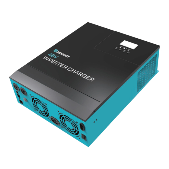
- Page 1 INVERTER CHARGER 48V Pure Sine Wave Inverter & Charger 5000w Version 1.0...
-
Page 2: Important Safety Instructions
Important Safety Instructions Please save these instructions. This manual contains all safety, installation and operating instructions for the Inverter Charger. The following symbols are used throughout the manual: Indicates a potentially dangerous condition. Use extreme caution WARNING when performing this task. Indicates a critical procedure for safe and proper operation of the CAUTION inverter. - Page 3 Battery Safety Do NOT let the positive (+) and negative (-) terminals of the battery touch each other. Use Lithium batteries or deep cycle Sealed Lead Acid, Flooded, Gel, AGM batteries. Explosive battery gases may be present while charging. Be certain there is enough ventilation to release the gases.
-
Page 4: Table Of Contents
Table of Contents Important Safety Instructions General Information Battery Charging Modes: Load Output Working Modes Product Overview Identification of Parts Dimensions Optional Components Installation Location Recommendations Wiring Battery Wiring AC Output Wiring AC Input Wiring Communication Ports Dry Contacts RS485 Operation LCD Operation LCD Menu... -
Page 5: General Information
General Information The new all-in-one Renogy Inverter Charger is an advanced hybrid system combining the advanced charging algorithm with industrial reliability and electrical energy of pure sine wave inverters to give you a complete power system. The AC-DC charging module adopts an advanced control algorithm resulting in a powerful battery charger. - Page 6 UTILITY 48V Battery Storage Power or generator (Utility): Access at the AC input can power the load and charge the battery. If you do not have a power supply or generator, the system can also operate normally, where the load is supplied by batteries. Battery: The role of the battery is to ensure the normal use of electricity for the system load.
-
Page 7: Battery Charging Modes
Battery Charging Modes: CHARGING CHARGING Load Output Working Modes The inverter has 2 working modes that dictate how the incoming power is used to power the loads.Users may configure the output source priority to configure load power. Utility Priority Equivalent to a backup UPS for use in unstable areas of the grid, Utility will provide power to the loads as priority. -
Page 8: Product Overview
Product Overview Identification of Parts REMOTE Key Parts 1. LCD Buttons 8. USB Debugging Port (Internal Use) 2. Mounting Holes 9. AC Input Terminal 3. LCD Screen 10. AC Output Terminal 4. LED Indicators 11. Wired Remote Port 5. AC Input Breaker 12. -
Page 9: Dimensions
Optional Components Renogy BT-2 Bluetooth Module: The BT-2 Bluetooth module is a great addition to any Renogy charge controllers with a RS485 port and is used to pair charge controllers with the DC HOME App. After pairing is done you can monitor your system and change parameters directly from you cell phone. -
Page 10: Installation
Installation Please read this manual carefully and familiarize yourself with the installation procedures before installation. Indicates a potentially dangerous condition. Use extreme caution WARNING when performing this task. Indicates a critical procedure for safe and proper operation of the CAUTION inverter. - Page 11 Other Precautions: When installing the battery, be very careful, when installing lead-acid liquid batteries, you should wear protective glasses, once in contact with battery acid, please wash with water in time. Avoid placing metal objects near the battery to prevent short circuits in the battery. Acid gas may be generated when the battery is charged so ensure good ventilation around the environment.
-
Page 12: Wiring
Wiring The Renogy Inverter is suitable for 48V battery banks systems ONLY. Not WARNING following the minimum DC requirement may cause irreversible damage to the unit. Be careful of the positive and negative poles. Reversing the poles may cause CAUTION permanent damage to the inverter. -
Page 13: Battery Wiring
Wiring and installation methods must comply with national and local electrical specifications. The following chart is reference only. Longer wire runs between the inverter and battery bank will require thicker wiring size to minimize loss and improve system performance. Minimum Recommended Specification Max Amps Wiring AWG... -
Page 14: Ac Output Wiring
The inverter takes a 48V battery input to operate. This will require combining 12V or 6V batteries in series to achieve the minimum voltage DC requirement. It is recommended to use battery cables with ring terminals. The ring terminals must be firmly tightened and secured on the respective battery terminals to prevent any excessive heating or resistance. -
Page 15: Ac Input Wiring
:Ground | L:Live | N:Neutral AC Input Wiring The AC input must never be connected to the AC output as irreversible overload or WARNING damage may result The AC Input Terminal Block is connected to circuit breakers for added protection. Do NOTE not modify or alter them as it may cause irreversible damage to the inverter. -
Page 16: Communication Ports
Communication Ports Dry Contacts To use this to function, an auto start controller must be installed on the generator. NOTE there are three contacts; up to down: NO, N, NC Do not store units with auto gen start feature enabled. Generators exhaust WARNING dangerous fumes when running. -
Page 17: Operation
Operation Assuming all connections are correct and tightly secured, Locate the power button on the inverter and turn the main power switch to the ON position. The following describes the basic operation of the inverter charger LCD Operation The inverter is equipped with 3 LCD indicators and 4 working buttons AC/INV CHARGE FAULT... - Page 18 ① ② ③ ④ ⑤ Indicates that the battery is Indicates that the utility/grid is powering the inverter circuit powering the load (DC-AC) Indicates that the power utility/grid Indicates that the inverter circuit is is powering the battery charging powering the load circuit (AC-DC) The arrow only displays during startup and not part of the inverter...
- Page 19 Icon Function Icon Function Indicates that the AC input is Indicates that the inverter connected to AC Source mode circuit is working This icon indicates a wide Indicates that the inverter voltage AC input Mode (APL charger is in the power bypass mode) (Bypass) Indicates that the inverter...
- Page 20 The following is on the left side of the LCD Indicates AC input Indicates inverter circuit The icon appears only at startup and is irrelevant to functionality of the inverter Shows battery voltage, total battery charge current, charge power, AC input voltage, AC input frequency, internal heatsink temperature, and software version The following is on the right side of the LCD...
-
Page 21: Lcd Menu
Wired Remote The wired remote control is an alternative way to power on or off your solar inverter from a distance. To operate: 1. Make sure the push button on the wired remote is not pressed 2. Flip the solar inverter switch to OFF mode 3. -
Page 22: Lcd Programmable Features
LCD Programmable Features Press the "SET" key to enter parameter setting mode. After entering the settings menu, the parameter number 00 flashes and you can press the "UP" and "DOWN" keys to select the parameter code that you want to set. To access the parameter program press "ENT" key to enter the parameter editing state, at which point the value of the parameter flashes. - Page 23 Parameters Number Parameter Name Set options Description User-defined, all battery [08] USE parameters can be set Sealed lead-acid battery, [08] SLd constant voltage charging 58.4V, (Default) floating charging voltage 55.2V Flooded lead-acid battery,constant [08] FLd voltage charging 58.4V,floating charging voltage 55.2V Gel lead-acid battery, constant [08] GEL voltage charging 56.8V,floating...
- Page 24 Parameters Number Set options Parameter Name Description Changes the charging voltage Boost Charge [09] 58.4V *available in USER setting, set the range 48V to 58.4V, Voltage (Default) and lithium setting in 0.4V increments only Raise the charging maximum time setting, refers to the constant *available in USER [10] 120 min Boost Charge...
- Page 25 Parameters Number Set options Parameter Name Description Warning that the battery is Battery *available in USER approaching low voltage. The output [14] 44V Undervoltage and lithium setting does not shut down and the range is (Default) Alarm only 40V to 52V, in 0.4V increments When the battery voltage goes below this voltage set-point, the *available in USER...
- Page 26 Parameters Number Set options Parameter Name Description Overload automatic restart is [23] DIS disabled, and the unit will not turn on the loads Enables automatic restart if the Overload load shutdown output has auto-start occurred. The unit attempts to [23] ENA restart the output after 3 minutes (Default) and After 5 attempts the unit will...
- Page 27 Parameters Number Set options Parameter Name Description Set point that recovers and reconnects the solar inverter from Low Voltage [35] 50.4V being disconnected in Low Disconnect (Default) Voltage Disconnect. The range is Recover from 44V -58.4V, in 0.4V increments. [36] 80A Adjustable PV current settings.
-
Page 28: Electronic Protections
Electronic Protections Number Protection Description Overvoltage Protection Triggered when AC Input voltage reaches 280V Power Input Under- When utility input is below 170VAC, charging is voltage Protection stopped and the inverter is in inverter mode When the battery voltage reaches the overvoltage disconnect point, the utility automatically stop Battery Over-voltage charging the battery, preventing damage from... -
Page 29: Fault Codes
Fault Codes Fault code Fault name Description BatVoltLow Battery under-voltage alert 【01】 BatOverCurrSw Battery discharge current software protection 【02】 BatOpen Battery not detected 【03】 BatLowEod Battery undervoltage stopdischarge alarm 【04】 BatOverCurrHw Battery overcurrent hardware protection 【05】 BatOverVolt Charge overvoltage protection 【06】... -
Page 30: Maintenance
Fault Solutions Make sure the battery is properly connected and charged to Screen not displaying be able to recognize the inverter. or click any button on the screen to exit screen sleep mode. Rechargeable battery Measure whether the battery voltage exceeds 60Vand overvoltage protection disconnect the photovoltaic array from and the power-on. -
Page 31: Technical Specifications
Technical Specifications Model RIV4850CH2S Utility/Grid Rated input Voltage 220/230Vac Input voltage range (90Vac~280Vac)+/-2% 50Hz/ 60Hz (auto detect) Frequency 47-0.3Hz x 55-0.3Hz (50Hz); Frequency range 57-0.3Hz x 65-0.3Hz (60Hz); Breaker Overload / Short circuit Protection >95% Efficiency Conversion time (Bypass and reverse) - Page 32 Model RIV4850CH2S Utility/Grid Charging Battery type Lead Acid or Lithium Maximum Charging Power (AC) ± 5Adc Unstable Condition Error 40-60Vdc Charging Voltage Range Breakers and fuses Short-circuit protection Circuit Breaker Specifications Yes; Automatically alerts and then turns off Overcharge Protection...
- Page 33 Non-Lithium Battery Parameters Flooded USER Battery type SLD/ Lead Acid Custom Range Parameters (Default) (FLD) Overvoltage Disconnect Overvoltage 58.2V 58.2V 58.2V 58.2V Disconnect Recover Equalization 59.2V 59.2V 48~59.2V (adjustable) Voltage[16] 58.4V Boost Voltage[9] 58.4V 56.8V 58.4V 48~58.4V (adjustable) 55.2V 55.2V 55.2V 55.2V 48~58.4V...
- Page 34 Lithium Battery Parameters Lithium Iron Phosphate Lithium-ion Battery type USER Custom (LF16) (LF15) (LF14) (n14) (n13) Parameters (Default) Range Overvoltage Disconnect Overvoltage 58.2V 58.2V 58.2V 58.2V 58.2V 58.2V Disconnect Recover 59.2V Equalization 48~59.2V Voltage[16] (adjustable) 57.6V 50.4V 57.2V 53.2V 58.4V Boost 48~58.4V Voltage[09]...
- Page 35 When modifying parameters in User Mode or Lithium, the following rules must be followed to set parameters successfully. Overvoltage Disconnect > Overvoltage Disconnect Recover ≥ Equalization voltage ≥ Boost voltage ≥ Float voltage Overvoltage Disconnect > Over Voltage Disconnect Recover Low Voltage Disconnect Recover >...
-
Page 36: Charging Parameters Glossary
Charging Parameters Glossary Overvoltage Disconnect—When and if the charge controller experiences a voltage higher than what is assigned, it will disconnect itself from the circuit; ceasing charge. Overvoltage Recover-- in the event a charge controller experiences an over-voltage condition set by the previous parameter, then this reconnecting parameter is put into play to direct the controller when it can connect and safely charge again. - Page 37 Discharging limit Voltage-- This parameter ensures that the controller does not exceed the default or assigned parameter before needing to be charged again. This is put into play to optimize and extend the battery life by going with a higher voltage. The lower the discharge limit voltage the more negative effect on battery efficiency.
- Page 38 RENOGY.COM Renogy reserves the right to change the contents of this manual without notice. 2775 E Philadelphia St, Ontario, CA 91761, USA 909-287-7111 www.renogy.com support@renogy.com 苏州高新区科技城培源路1号5号楼-4 400-6636-695 https://www.renogy.cn support@renogy.cn https://www.renogy.jp supportjp@renogy.com https://ca.renogy.com supportca@renogy.com https://au.renogy.com supportau@renogy.com https://uk.renogy.com supportuk@renogy.com https://de.renogy.com supportde@renogy.com...
Need help?
Do you have a question about the RIV4850CH2S and is the answer not in the manual?
Questions and answers