
Subscribe to Our Youtube Channel
Related Manuals for Renogy RBC2125DS-21W


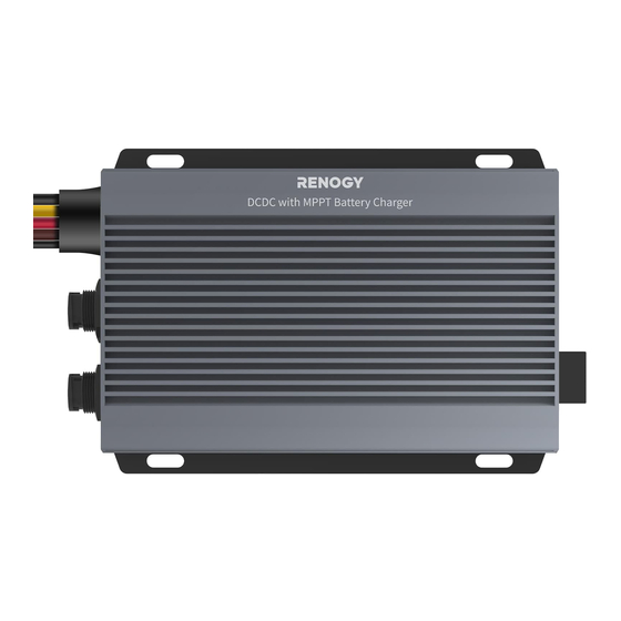
Summary of Contents for Renogy RBC2125DS-21W
- Page 1 Renogy Dual Input DC-DC On-Board with MPPT Battery Charger 12V/24V 50A IP67 VERSION A0 RBC2125DS-21W January 5, 2024 USER MANUAL...
- Page 2 The illustrations in the user manual are for demonstration purposes only. Details may appear slightly different depending on product revision and market region. z Renogy reserves the right to change the information in the user manual without notice. For the latest user manual, visit renogy.com.
-
Page 3: Table Of Contents
Table of Contents General Information ........................... 1 1.1. Symbols Used .............................. 1 1.2. Introduction ..............................1 1.3. Key Features ..............................1 1.4. SKU ................................. 1 Get to Know 12V/24V 50A DC-DC Battery Charger with MPPT ............. 2 2.1. What’s In the Box? ............................2 2.2. - Page 4 10.1. Dimensions ..............................39 10.2. Technical Specifications ......................... 39 11. Maintenance ............................. 40 11.1. Inspection ..............................40 11.2. Cleaning ..............................40 11.3. Storage ...............................40 12. Emergency Responses ........................41 12.1. Fire ................................41 12.2. Flooding ..............................41 12.3. Smell ................................41 12.4. Noise ................................41 Renogy Support ............................42...
-
Page 5: General Information
NOTE: Indicates an important step or tip for optimal performance. 1.2. Introduction Renogy 12V/24V 50A IP67 Dual Input DC-DC On-Board with MPPT Battery Charger allows you to charge your house (auxiliary) battery from solar panels or the starter battery in your RV. It is a charging... -
Page 6: Get To Know 12V/24V 50A Dc-Dc Battery Charger With Mppt
Get to Know 12V/24V 50A DC-DC Battery Charger with MPPT 2.1. What’s In the Box? Renogy 12V/24V 50A IP67 Renogy Dual Input DC-DC On-Board Dual Input DC-DC On-Board with MPPT Battery Charger ST4*20 mm 12V/24V 50A IP67 VERSION A0 RBC2125DS-21W January 5, 2024 with MPPT Battery Charger ×... -
Page 7: System Setup
Starter Battery DC-DC Battery Charger RV-C or Renogy devices supporting CAN communication The wiring diagram only shows the key components in a typical DC-coupled off-grid energy storage system for the illustrative purpose. The wiring might be different depending on the system configuration. -
Page 8: Preparation
Preparation 3.1. Recommended Tools & Accessories Phillips Screwdriver (#1) Insulating Gloves Wire stripper Insulation Tape Measuring Tape Bare Wires Butt-Splices Heat Gun Manual Hydraulic Pliers Heat Shrink Tubing 3/8 in Lugs (M10 Ring Terminals) Busbar (60A to 100A) Prior to installing and configuring the battery charger, prepare the recommended tools, components, and accessories. -
Page 9: Size Wires
3.2. Size Wires Select proper bare wires based on the cable length in your power system. Refer to the table below for recommended gauge sizes. Cable Cable Length Cable Gauge Size 0 ft to 10 ft (0 m to 3 m) 10 AWG (5.25 mm²) Output 11 ft to 20 ft (3 m to 6 m) -
Page 10: Check The Battery Charger
Do not expose the battery charger to flammable or harsh chemicals or vapors. Make sure that the battery charger is installed in a place at ambient temperature from -31°F to 176°F (-35°C to 80°C). Make sure that the battery charger is installed in an environment with relative humidity between 0% and 95% and no condensation. -
Page 11: Check The Auxiliary Battery
Recommended Components & Accessories *12V/24V Battery (11V to 32V) *ANL Fuse (60A) × 1 Components and accessories marked with “*” are available on renogy.com. 1. Inspect the battery for any visible damage including cracks, dents, deformation, and other visible abnormalities. All terminals shall be clean, free of dirt and corrosion, and dry. -
Page 12: Check The Solar Panel(S)
Recommended Components & Accessories *Solar Panel (s) *Solar Panel Fuse *Solar Panel Extension Cables × 2 Components and accessories marked with “*” are available on renogy.com. For how to size solar panel extension cables, refer to “3.2. Size Wires” in this manual. - Page 13 Do not step, walk, stand, or jump on the solar panel. Localized heavy loads may cause damage to the solar cells, which will ultimately compromise the performance of the solar panel. Do not bend the solar panel. Bending the solar panel will cause damage to the cells and affect panel performance.
-
Page 14: Check The Alternator On Your Automobile
Recommended Components *ANL Fuse (70A) × 1 Accessories marked with “*” are available on renogy.com. The automobile alternator may be a smart alternator or a traditional alternator. The connection method of a smart alternator or a traditional alternator depends on its parameters. Before installing the battery charger, read the user manual of the vehicle or consult the vehicle supplier to determine the type of alternator. -
Page 15: How To Install 15/32 In Lugs Or 3/8 In Lugs
In general, the working voltage of a traditional alternator ranges from 13.2V to 16V, and that of a smart alternator ranges from 12V to 16V. Consult the vehicle supplier for help if necessary. 3.8. How to Install 15/32 in Lugs or 3/8 in Lugs? Step 1: Strip approximately 0.4 inches (10 mm) of insulation from 0.4 in the end of a bare wire using a wire stripper. -
Page 16: How To Install Cables On The Battery Charger
Step 5: Slide the heat shrink tubing over the 15/32-inch lug or 3/8- inch lug. Step 6: Apply heat to the heat shrink tubing using a heat gun until it shrinks and forms a tight seal. 3.9. How to Install Cables on the Battery Charger? You are allowed to make connections using insulated conduit, junction boxes, or welding methods. - Page 17 Step 3: Thread the exposed bare wire through a piece of heat shrink tubing. Heat Shrink Tubing Step 4: Insert the Positive Auxiliary Battery Cable and bare wire into the butt-splices. Step 5: Securely crimp the butt-splices onto the cables using a manual hydraulic pliers.
- Page 18 Step 7: Apply heat to the heat shrink tubing using a heat gun until it shrinks and forms a tight seal. █ Negative Cable For the negative terminals, we recommend a busbar. Install the 3/8-inch lugs (M10 ring terminals) on the solar panel, auxiliary battery, starter battery negative cables, and battery charger negative common cable (black) on the busbar.
-
Page 19: Installation
Installation To ensure safe and efficient operation of the battery charger and to avoid potential damage or hazards, always follow the installation instructions in the sequence described in this manual. 4.1. Wear Insulating Gloves Insulating Gloves 4.2. Connect the Battery Charger to a Busbar Negative Common Cable (black) 3/8 in Lug (M10 Ring Terminal) -
Page 20: Connect The Battery Charger To An Auxiliary Battery
4.3. Connect the Battery Charger to an Auxiliary Battery The battery charger can only be connected to 12V or 24V deep-cycle gel-sealed lead-acid batteries (GEL), flooded lead-acid batteries (FLD), sealed lead-acid batteries (SLD/AGM) or lithium iron phosphate batteries (LI). Step 1: Connect one positive cable (red) to the Positive Auxiliary Battery Cable (brown) on the battery charger. -
Page 21: Connect The Battery Charger To A Solar Panel
4.4. Connect the Battery Charger to a Solar Panel Choose proper solar panels based on your power system. Connecting the battery charger to a solar panel exceeding 720W (≤50V) results in damage to the battery charger. Step 1: Connect the positive Solar Panel Extension Cable to the Positive Solar Cable (yellow) on the battery charger. -
Page 22: Connect The Battery Charger To A Starter Battery
4.5. Connect the Battery Charger to a Starter Battery Before installing the charger, consult your vehicle’s user manual or contact the vehicle manufacturer to ensure that the alternator power does not exceed 720W with the output current of 75A to 100A. The starter battery stops charging the auxiliary battery when the starter battery voltage drops below 12.7V for 12V systems or 25.4V for 24V systems. -
Page 23: Install A Battery Temperature Sensor
RV-C, enabling safe operation, smart control, remote monitoring, and programmable settings. You can connect the battery charger to other Renogy devices supporting CAN communication for real-time inter-device data communication through either of the CAN Communication Ports. 7-Pin CAN Communication Terminal Plugs and 7-Pin CAN Communication Terminal Plug adapter cables are required for the wiring. - Page 24 The drop taps are usually located above the entry door, in the bathroom, or under the bed in the RV. Step 4: Connect the Drop Plugs on the drop cables and other Renogy devices supporting CAN communication to the drop sockets on the drop tap.
- Page 25 Please select the appropriate adapter cable based on the type of the CAN Communication Port specific to the device. For example: z Battery Charger to RENOGY ONE: 7-Pin CAN Communication Terminal Plug to RJ45 Communication Adapter Cable z Battery Charger to REGO devices: 7-Pin CAN Communication Terminal Plug to LP16 Plug (7-Pin)
- Page 26 Accessories marked with “*” are available on renogy.com. The communication cable should be less than 19.6 feet (6 m). The quantity of adapter cables and plugs varies based on the position of the battery charger in the daisy chain network. When the battery charger is positioned at either the first or the last device in the daisy chain network, one 7-Pin CAN Communication Terminal Plug and one adapter cable are required.
-
Page 27: Wire Inspection
Battery Charger is in the Middle of the Daisy Chain Network STEP-1 Install Cables on devices STEP-2 Install Plugs on devices 4.8. Wire Inspection Verify that all cable connections are firmly and securely fastened. This step is essential to prevent any loose or unstable connections that could lead to operational issues or safety concerns. -
Page 28: Led Indicators
LED Indicators The battery charger turns on automatically after power on with the LED indicators working in accordance with the relative operating status. Solar Charging Indicator Battery Type Indicator Off: Not charging Solid: Solid: Solid: MPPT charging Slow flash: Boost charging Solid: SLD/AGM Single flash:... -
Page 29: Configuration
Configuration 6.1. Set a Battery Type Upon installing the battery charger, set a correct battery type by using the Battery Type Setting Button. A successful setting of the battery type is indicated by all LEDs illuminating from left to right (Solar to Type). -
Page 30: Configure Charging Parameters
The battery charger has a User Mode, and the specific default parameter values and customizable parameters should be primarily based on the actual displays in the DC Home app or Renogy ONE. This table assumes default parameters for a 12V system. If the system voltage is 24V, double the values. -
Page 31: Activate Lithium Batteries
Battery Type SLD/AGM FLOODED LI (LFP) Parameters Equalization Interval 30 days — 30 days — Temperature Compensation -3 mV / °C / 2V -3 mV / °C / 2V -3 mV / °C / 2V — 6.4. Activate Lithium Batteries The battery charger can activate connected lithium batteries. -
Page 32: Monitoring
Step 1: Open the DC Home app. Tap + to search for new devices. Step 2: Tap Confirm to add the newly found device to the device list. Step 3: Tap the battery charger icon to enter the device information interface. My Renogy My Renogy HUB Mode... -
Page 33: Wireless Long-Range Monitoring
Step 1: Connect the battery charger to Renogy ONE through the Bluetooth of your phone. Step 2: Pair the Renogy ONE with the DC Home app through Wi-Fi or by scanning the QR code in the Renogy ONE. On Renogy ONE, go to “System > Settings > Pair with App” to get the QR code. -
Page 34: Wired Long-Range Monitoring (Backbone Network)
7.3. Wired Long-Range Monitoring (Backbone Network) If long-range communication and programming are required, connect the battery charger to Renogy ONE through a RJ45 Plug to Bare Drop cable, and the Renogy ONE to the DC Home app through Wi-Fi. Recommended Components & Accessories... -
Page 35: Wired Long-Range Monitoring (Daisy Chain Network)
Step 2: Connect the Renogy ONE to the free CAN Communication Port on the Renogy devices supporting CAN communication with the Communication Adapter Cable (sold separately). Step 3: Pair Renogy ONE with the DC Home app. Monitor and program the complete system on the Renogy ONE or the DC Home app. -
Page 36: Working & Charging Logic
Working & Charging Logic 8.1. Automatic Voltage Matching Function Whether you are connecting a 12V or 24V solar panel or starter battery, this battery charger will automatically adjust the charging current and voltage values based on the rated voltage of the battery being charged. -
Page 37: Charging Logic
8.2. Charging Logic The battery charger allows you to charge the auxiliary battery with a starter battery connected to an alternator, with solar panels connected directly to the battery charger, or with both solar panel and starter battery. The charging logic depends on the connection method. The battery charger employs the “Solar Power Green Priority”... - Page 38 █ When Solar-Generated Power is Severely Inadequate When solar power is severely inadequate, the battery charger charges the auxiliary battery by utilizing only the starter battery. Starter Battery Working Conditions Stop Conditions Nominal Voltage Solar output current < LowSolar Current Shuntdown Solar output current >...
-
Page 39: Battery Charging Stages
8.3. Battery Charging Stages The battery charger utilizes cutting-edge MPPT technology to efficiently track the maximum power output of solar panels in various conditions, ensuring real-time optimization. It also incorporates four distinct charging stages: bulk, boost, float, and equalization. Reset to Bulk Bulk Float... - Page 40 During Equalization charging, the battery charger remains in this stage until sufficient charging current is sourced from the solar panel. Note that there should be no load on the batteries during Equalization charging.. Overcharging and excessive gas precipitation can harm battery plates, leading to material shedding.
-
Page 41: Troubleshooting
Troubleshooting This section discusses general troubleshooting tips specific to LED indicator status. Fault Possible Cause Solution z The output voltage of the solar panel is z For solar panel voltage under below 15V. 15V, ensure there is no shade or damage on the solar panel. - Page 42 176°F (-35°C to 80°C). When the battery charger. temperature exceeds 149°F (65°C), the charger will decrease its load. If the temperature exceeds 176°F (80°C), the battery charger will stop working. For technical support, contact our technical service through renogy.com/contact-us. — 38 —...
-
Page 43: Dimensions & Specifications
10. Dimensions & Specifications 10.1. Dimensions 12 in (305 mm) 4.84 in (123 mm) 4.06 in (103 mm) 1.46 in (37 mm) 0.2 in (5 mm) 4.72 in (120 mm) 6.5 in (165 mm) 7 in (178 mm) Dimension tolerance: ±0.2 in (0.5 mm) 10.2. -
Page 44: Maintenance
11. Maintenance 11.1. Inspection For optimum performance, it is recommended to perform these tasks regularly. z Ensure the battery charger is installed in a clean, dry, and ventilated area. z Ensure there is no damage or wear on the cables. z Ensure the firmness of the connectors and check if there are any loose, damaged or burnt connections. -
Page 45: Emergency Responses
2. Make sure no foreign objects are stuck in the fan of the battery charger or the ring terminal. The normal noise value of the battery charger is less than 30dB during operation. If the noise is abnormal, contact our technical service through renogy.com/contact-us. — 41 —... -
Page 46: Renogy Support
Questionnaire Investigation To explore more possibilities of solar systems, visit Renogy Learning Center at: renogy.com/learning-center For technical questions about your product in the U.S., contact the Renogy technical support team through: renogy.com/contact-us 1(909)2877111 For technical support outside the U.S., visit the local website below: Canada ca.renogy.com... - Page 47 FCC Statement This device complies with Part 15 of the FCC Rules. Operation is subject to the following two conditions: (1) This device may not cause harmful interference. (2) This device must accept any interference received, including interference that may cause undesired operation.
- Page 48 Save 105 gallons of water from being consumed Renogy Power PLUS Renogy Power Plus allows you to stay in the loop with upcoming solar energy innovations, share your experiences with your solar energy journey, and connect with like-minded people who are changing the world in the Renogy Power Plus community.
Need help?
Do you have a question about the RBC2125DS-21W and is the answer not in the manual?
Questions and answers