
Subscribe to Our Youtube Channel
Related Manuals for Automationdirect.com Stride SIOL-EI8B


Summary of Contents for Automationdirect.com Stride SIOL-EI8B
- Page 1 SIOL-EI8B IO-Link Master Basic EtherNet/IP DIO8 IOL8 M12L 5P Powered by User Manual #SIOL-EI8B-USER-M...
- Page 2 ~ WARNING ~ Thank you for purchasing automation equipment from Automationdirect.com , doing business ® as AutomationDirect. We want your new automation equipment to operate safely. Anyone who installs or uses this equipment should read this publication (and any other relevant publications) before installing or operating the equipment.
- Page 3 (“Actividades de Alto Riesgo”). Automationdirect.com específicamente rechaza cualquier garantía ya sea expresada o implicada para actividades de alto riesgo.
- Page 4 ® Tous droits réservés Nulle partie de ce manuel ne doit être copiée, reproduite ou transmise de quelque façon que ce soit sans le consentement préalable écrit de la société Automationdirect.com Incorporated. ® AutomationDirect conserve les droits exclusifs à l’égard de tous les renseignements contenus dans le...
- Page 5 Stride IO-Link Master Basic User Manual Please include the Manual Number and the Manual Issue, both shown below, when communicating with Technical Support regarding this publication. Manual Number: SIOL-EI8B-USER-M Issue: 1st Edition Issue Date: 05/2022 Publication History Issue Date Description of Changes 1st Edition 05/2022 Original release...
-
Page 6: Table Of Contents
Table of Contents Powered by Table of Contents Introduction 1.1. Applicable documents 1.2. About this manual 1.2.1. Symbols 1.2.2. Trademarks 1.2.3. Specifications 1.2.4. Software tools For your safety 2.1. General safety instructions 2.2. Intended purpose Description 3.1. Module 3.1.1. Product Designation Code 3.1.2. - Page 7 Table of Contents Powered by Installation 6.1. Electrical Installation of the Module 6.1.1. Connecting sensors and actuators 6.1.2. Connecting Ethernet bus 6.1.3. Connecting the power supply 6.2. Ensuring Tightness (IP67) Startup 7.1. Loading the EDS files 7.2. Adding a module as an EtherNet/IP Device 7.3.
- Page 8 Table of Contents Powered by 9.3.1. Reading an IO-Link device index 9.3.2. Writing an IO-Link device index 9.3.3. CIP status codes Web Server (WebUI) 10.1. Starting the WebUI 10.2. Menu bar 10.2.1. STATUS menu 10.2.2. PARAMETERS menu 10.2.3. DIAGNOSTICS menu 10.2.4.
- Page 9 Table of Contents Powered by B.3. Diagnostic Buffer B.4. Digital Output Appendix C: Configuring a Module Using Studio5000 Logix Designer C.1. Loading the EDS files C.2. Adding a module to the network C.3. Module configuration C.4. RPI configuration Glossary Legal notes SIOL-EI8B-USER-M Version 1, May 2022...
-
Page 10: Introduction
Introduction Powered by Introduction Function of this document This document instructs the technical personnel of the machine manufacturer or machine operator on the safe use of the devices described in the scope. It does not include instructions on the safe use of the machine in which the devices are or will be integrated. -
Page 11: About This Manual
Introduction Powered by 1.2. About this manual 1.2.1. Symbols This document includes information and notes that must be observed for your own safety and to avoid injuries and equipment damage. They are marked as follows: ⚠ DANGER! Immediate danger Failure to observe this warning involves an imminent risk of death or serious injuries. ⚠... -
Page 12: For Your Safety
For your safety Powered by For your safety ➔ Read this chapter carefully before working with the fieldbus module. 2.1. General safety instructions ⚠ DANGER! High electrical voltage in the machine/system Death or severe injuries resulting from electric shock. ➔ When working on the machine or modules, comply with all applicable requirements and recommendations. -
Page 13: Intended Purpose
For your safety Powered by ⚠ CAUTION! Hot surface! Minor injuries and damage to devices caused by contact with the surface. ➔ Wear thermally suitable gloves. ➔ Use thermally suitable connecting cables only. Protective measures by the machine operator ➔ Follow the instructions in this manual. -
Page 14: Description
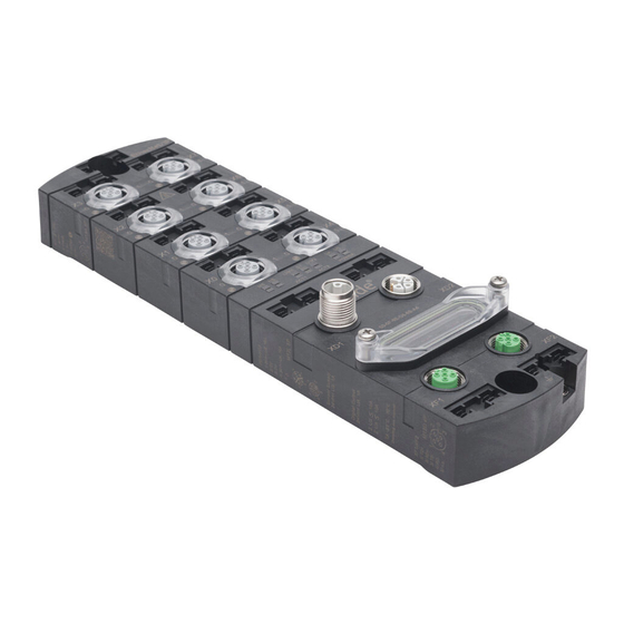
Description Powered by Description 3.1. Module The STRIDE IO-Link master is a fully encapsulated fieldbus module in a plastic case. It is particularly robust and designed for use in harsh environments. Property Description Versatile applications exposed to harsh environments due to: ◼... -
Page 15: Module Structure
Description Powered by 3.1.2. Module structure X0–X7 Digital inputs and outputs or IO-Link, M12, A-coded Channel corresponds to pin 4 Channel corresponds to pin 2 Power supply POWER IN, M12, L-coded, 5-pin Power supply POWER OUT, M12, L-coded, 5-pin Rotary switch Ethernet port 1, M12, D-coded Ethernet port 2, M12, D-coded Ground strap for functional ground... -
Page 16: Connections
Description Powered by 3.1.3. Connections 3.1.3.1. Pin assignments M12 Female Connector, A-coded X0–X7 Pin 1 24VDC Pin 2 DI/DO Pin 3 Pin 4 DI/DO/IO-Link Pin 5 M12 Male/Female Connector, L-coded, POWER IN/OUT Pin 1 24VDC US (operating voltage) Pin 2 0V UA (actuator voltage) Pin 3 0V US... -
Page 17: Display Elements
Description Powered by 3.1.4. Display elements X0–X7 LED digital inputs and outputs or IO-Link LED MS (module configuration status) LED NS (network status) LED LNK1/ACT1 (Ethernet port 1 link/activity) LED ST (module overall status) LED LNK2/ACT2 (Ethernet port 2 link/activity) LED POWER UA (actuator voltage) LED POWER US (operating voltage) Fig. -
Page 18: Rotary Switch Settings
Description Powered by 3.1.5. Rotary switch settings NOTE In the default state, the rotary switches are set to 000, DHCP enabled. NOTE A unique IP address must be assigned to each device in the network. Setting the IP Address on the Rotary Switches Address range: 1–999 Rotary switch 9ones) Rotry switch (tens) -
Page 19: Io-Link
Description Powered by 3.2. IO-Link IO-Link is a standardized protocol that enables connection of intelligent devices (sensors and actuators) to an automation system. Communication takes place between an IO-Link master and one or more IO-Link devices. A master module has one or more ports and one device can be connected to each port. IO-Link is a point-to-point communication system and is not a fieldbus. -
Page 20: Data Storage
Description Powered by 3.2.1. Data storage NOTE Data storage is only available for devices that comply with IO-Link version V1.1 and higher. ◼ Data storage offers the ability to replace IO-Link devices without reconfiguration. ◼ The IO-Link master or the IO-Link device saves the set device parameters of the previous configuration. -
Page 21: Ethernet/Ip
Description Powered by 3.3. EtherNet/IP 3.3.1. Communication EtherNet/IP is based on a Producer/Consumer communication model for which the multicast Ethernet communication enables fast “Report by exception” responses. The connection to the control scanner can only be established in an EtherNet/IP network via 10/100MBit/s Ethernet switches. -
Page 22: Rpi
Description Powered by 3.3.2. Requested Packet Interval (RPI) When setting up an EtherNet/IP system, the RPI value must be carefully set in the scanner. The RPI value determines the speed at which the scanner sends EtherNet/IP messages (packets). It also determines the maximum speed at which the bus node sends messages. -
Page 23: Technical Data
Technical Data Powered by Technical Data 4.1. Electrical Data Functions http Web Interface Current and voltage Energy monitoring Temperature monitoring Bus Data EtherNet/IP Fieldbus protocol 10/100 Mbit/s Ethernet BOOTP, DHCP, WebUI, Rotary encoder switch Addressing Exclusive Owner, Listen Only, Input Only Connection types Beacon-based Device Level Ring (DLR) - Page 24 Technical Data Powered by Input (DI) Per Port ≤60°C [140°F] (see Derating) ≤1A load Automatic start Sensor power supply ≤40°C [104°F] (see Derating) ≤10A Total current Sensor supply 0–15 ms + tcycle, adjustable Filter time 2–5 ms Delay time for signal change EN 61131-2 Type 1 + Type 3 Input characteristic...
- Page 25 Technical Data Powered by Derating Charts Fig. 4-1: Sensor current US and actuator current UA. Fig. 4-2: Total current, sensor power supplies Total current, outputs. Fig. 4-3: Derating Current per sensor power supply and output. SIOL-EI8B-USER-M Version 1, May 2022...
-
Page 26: Environmental Characteristics
Technical Data Powered by 4.2. Environmental characteristics Environmental -25°C to +70°C [-13°F to +158°F] Operating temperature Provide acclimatization for commissioning -25°C to +85°C [-13°F to +185°F] Storage temperature ≤95% Relative humidity Above sea level ≤3000m Installation height Mechanical 10–58 Hz, EN 60068 Part 2-6 Oscillation angle 0.35 mm, Vibration test... -
Page 27: Mechanical Data
Technical Data Powered by 4.4. Mechanical data Materials Plastic Housing material Assembly Data 470g [16.6 oz] Weight L x W x H 225.4 x 63 x 36 mm [8.874 x 2.5 x 1.4 in] Dimensions 4.5. Conformity, Approvals Conformity, Approvals EN 61131-2 Product standard Programmable logic controllers... -
Page 28: Mounting
Mounting Powered by Mounting 5.1. Requirements ➔ Mount on a flat mounting surface to avoid mechanical tension. ➔ Provide suitable grounding. ➔ Select a suitable installation site in terms of vibration and shock load, temperature and humidity (see Section 4, “Technical Data”). ➔... -
Page 29: Mounting Clearance
Mounting Powered by 5.3. Mounting clearance ≥3 [0.12] ≥3 [0.12] Fig. 5-2: Mounting clearance, mm [in]. NOTE ➔ For correct installation and improved heat dissipation, we recommend keeping a minimum distance of 3mm [0.12 in] when mounting the STRIDE IO-Link master. NOTE ➔... -
Page 30: Mounting The Module
Mounting Powered by 5.4. Mounting the module NOTICE Material damage due to incorrect installation The fastening screws and tightening torques depend on the surface of the installation site. ➔ Use fastening screws that are suitable for the mounting surface structure! ➔... -
Page 31: Functional Ground
Mounting Powered by Mounting Mount the module in the order indicated below: Slightly tighten the top M6 bolt. Align housing. Slightly tighten the lower M6 bolt. Tighten screws M6 according to the torque. Ground the module. Attach the grounding strap as shown in Section 5.4.1, “Functional ground”. NOTE The screws and the grounding strap illustrated are not included with the device. -
Page 32: Rotary Switch Cover
Mounting Powered by 5.4.2. Rotary switch cover Fig. 5-5: Rotary switch cover installation/removal. Screw Size Torque Tool Required Phillips Screwdriver, 0.8 N·m [7 in·lb] Part # TW-SD-PH-1 SIOL-EI8B-USER-M Version 1, May 2022... -
Page 33: Installation
Installation Powered by Installation 6.1. Electrical Installation of the Module ⚠ WARNING! Danger due to electric voltage in the machine / system. Electrical voltage in the system may result in death or fatal injuries. ➔ Observe all applicable safety requirements and recommendations. ➔... -
Page 34: Connecting Sensors And Actuators
Installation Powered by 6.1.1. Connecting sensors and actuators Connecting the M12 ports Fig. 6-1: Example of M12 connection inputs and outputs. Screw Size Torque Tool Required 0.6 N·m [5 in·lb] M12 Torque Wrench The pin assignment of the slots can be found in Section 3.1.3, “Connections”. NOTE Feeding in an external ground via M12 female connectors can lead to faults. -
Page 35: Connecting Ethernet Bus
Installation Powered by Sensor power supply Please note: ◼ Sensors can be supplied via pin 1 (24V) and pin 3 (0V) of the M12 female connectors. ◼ The maximum permissible current for the power supply of the sensors is 1A for the digital I/O port and 1A for the IO-Link port. -
Page 36: Connecting The Power Supply
Installation Powered by 6.1.3. Connecting the power supply Connect M12 male connector to POWER IN and M12 female connector to POWER OUT Fig. 6-3: Example of M12 connection (Power). Screw Size Torque Tool Required 0.6 N·m [5 in·lb] M12 Torque Wrench The pin assignment of the slots can be found in Section 3.1.3, “Connections”. -
Page 37: Ensuring Tightness (Ip67)
Installation Powered by 6.2. Ensuring Tightness (IP67) ⚠ CAUTION! Not properly sealed! Risk of personal injury and material damage due to failure caused by ingress of conductive liquids. ➔ Unused male and female connectors must be sealed. Connection of cables Fig. -
Page 38: Startup
Startup Powered by Startup ⚠ CAUTION! Uncontrolled processes Personal injury and material damage due to incorrectly performed start-up phases (e.g. first start-up, restart and configuration changes). ➔ Always perform the start-up in this sequence: Mount and connect cables to the module. System check and approval by an expert. -
Page 39: Loading The Eds Files
Powered by 7.1. Loading the EDS files This section describes how to configure a module, using Productivity Suite from AutomationDirect.com. The Stride Basic IO-Link Master can be used with EtherNet/IP scanners capable of Class 1 I/O Messaging (Implicit). Below, we show how to quickly get started using any EtherNet/IP capable Productivity PLC. - Page 40 Startup Powered by Navigate to your download location and double-click the EDS file you downloaded for your IO-Link Master. The EDS file will be added to your EDS library and is now searchable by Description, Part Number, Device Type, or Vendor. Fig.
-
Page 41: Adding A Module As An Ethernet/Ip Device
EtherNet/IP Device from the EtherNet/IP tab of the Hardware Config. NOTE AutomationDirect.com has created quick start code that can be imported into the task library and used to connect to the module. Code has also been developed for communicating with a variety of IO-Link field devices via the IO-Link Master module. - Page 42 Startup Powered by Fig. 7-6: EtherNet/IP Device Configuration. Click the icon to add a new EtherNet/IP message. A list of available connections will be displayed. The appropriate selection will depend on the connected IO-Link devices. For this example, we have selected the ‘Exclusive Owner (32B)’ Message. Fig.
- Page 43 Startup Powered by Specify a data array for both the T->O (INPUT) and O->T (OUTPUT) tabs. The required size of each array will depend on the selected Connection from step 3. Specify an integer tag for the Extended Status fields (not required). Fig.
- Page 44 Startup Powered by Fig. 7-9: EtherNet/IP Device O->T Configuration. The input and output tags created for T->O and O->T data can be found in the tag database (see the example in Fig. 7-10). Fig. 7-10: Tag Database – IO-Link Master Input and Output data tags. SIOL-EI8B-USER-M Version 1, May 2022...
- Page 45 Startup Powered by Select the Config Data tab and modify parameters as needed. Fig. 7-11: EtherNet/IP Device Config Data. When configured as desired, click OK. The Hardware Configuration window will now have the new EIP device that you just configured for the IO-Link Master. SIOL-EI8B-USER-M Version 1, May 2022...
-
Page 46: Productivity Suite Integration Library
(Note: you must be online with the CPU to do this). 7.3. Productivity Suite Integration Library AutomationDirect.com has created quick start code that can be imported into the task library and used to connect to the module. Code has also been developed for communicating with a variety of IO-Link field devices via the IO-Link Master module. - Page 47 Startup Powered by Fig. 7-13: Task Library – Import Group. Navigate to your download location, select the “Stride & Murr IO-Link_Masters.adtkl” file you downloaded for your IO-Link Master, and click Import. The Stride & Murr IO-Link_Masters group will be added to your Task Library. SIOL-EI8B-USER-M Version 1, May 2022...
- Page 48 Startup Powered by Fig. 7-14: Import Group – Stride & Murr IO-Link_Masters.adtkl. Fig. 7-15: Task Library – IO-Link Master Group. Drag the new task from the Task Library into the Run Every Scan task folder and click OK on the Tag Conversion pop-up.
- Page 49 Startup Powered by Fig. 7-16: Task Library – Drag and Drop Tasks. Under the EtherNet/IP tab of the Hardware Config, double-click or drag the IO-Link Master EDS file to the device area underneath the hardware tabs (see section 7.2 for more details). In the EtherNet/IP Client Properties do the following: Select Use Structure and enter/select the IO-Link Master.EIP_Device structure that was created as part of step 5.
- Page 50 Startup Powered by Fig. 7-17: EtherNet/IP Client Properties – IO-Link Master. SIOL-EI8B-USER-M Version 1, May 2022...
- Page 51 Startup Powered by Fig. 7-18: EtherNet/IP Client Properties – IO-Link Master O->T Data Array. Once all required field and tag entries have been made, per step 7, click OK and the EtherNet/IP Device will now appear in the hardware field. You are now ready to setup the quick start code for individual IO-Link field devices.
- Page 52 Startup Powered by Follow steps 3 and 4 to import the “Murr MVP IO-Link Hub.adtkl” to the task library. Then drag the new Murr MVP IO-Link Hub task from the library to the Run When Called task folder. Click OK on the Tag Conversion pop-up.
-
Page 53: Commissioning Without Eds
Startup Powered by 7.4. Commissioning without EDS NOTE The byte addresses shown in the tables in Section 7.4 use 0-based addressing. The Productivity Suite software uses 1-based addressing. So, add 1 to any address in these tables when accessing these values in Productivity Suite. - Page 54 Startup Powered by Assembly Instance 170 (continued) Instance Total size in bytes IO-Link port X7 188–211 Reserved 212–379 WebUI Reserved 381–383 Sequence of input bytes Assembly Instance 101 Instance Total size in bytes Digital input DI 0–1 DI Qualifier 2–5 System status 6–9 IO-Link port X0 input data...
-
Page 55: Configuration Values
Startup Powered by 7.4.4. Configuration values NOTICE ➔ To avoid unexpected behavior of the fieldbus device, use only the values listed in this manual. General parameters General Parameters Default Byte Parameters Value Description value IO Layout: Pin/Port Based IO Layout For Parameterizes the layout of the ◼... - Page 56 Startup Powered by IO-Link port X0–X7 parameters IO-Link Port X0–X7 Parameters Default Byte Parameters Value Description value ◼ 0 = Deactivated ◼ 1 = IO-Link Manual Configuration ◼ 2 = IO-Link Autostart IO-Link Function Pin 4 IO-Link function pin 4 ◼...
- Page 57 Startup Powered by WebUI parameters WebUI Parameters Default Byte Parameters Value Description value ◼ 0 = Disabled Use Of WebUI Activates or disables the WebUI ◼ 1 = Enabled Reserved Reserved for future use SIOL-EI8B-USER-M Version 1, May 2022...
-
Page 58: Configuration And Parameterization
There are two options for configuring the devices: ◼ Download an EDS file from the AutomationDirect.com website or the place of purchase. Then, import the EDS files into your programming software (see Section 7.1, “Loading the EDS files” for an example of how to do this). - Page 59 Configuration and parameterization Powered by Fig. 8-1: EtherNet/IP Device Config Data. Changes to configuration parameters must be transferred to the CPU. NOTE Configuration parameters are only transferred to the module during the Forward Open process and com- munication between the CPU and the module is briefly interrupted for configuration changes to take place. NOTE For more information on the adjustable parameter values, please refer to Section 7.4.4, “Configuration values”.
-
Page 60: Rpi Configuration
Configuration and parameterization Powered by 8.2. RPI configuration Setting the RPI values The RPI value is set in the EtherNet/IP Device properties, which is found in the EtherNet/IP tab of the Hardware Config. Fig. 8-2: EtherNet/IP Client Properties – T->O (Input) RPI Time. SIOL-EI8B-USER-M Version 1, May 2022... -
Page 61: Io-Link Configuration
Configuration and parameterization Powered by Fig. 8-3: EtherNet/IP Client Properties – O->T (Output) RPI Time. NOTE The minimum allowed RPI is 1 ms. 8.3. IO-Link configuration IO-Link configuration With the Basic IO-Link Master module, the IO-Link devices can be configured in two different ways: ◼... -
Page 62: Operation
Operation Powered by Operation 9.1. LED indication The module has separate and clearly arranged indicators: ◼ LED indication for inputs and outputs ◼ LED indication for bus ◼ LED indication POWER ◼ Extended LED indications The LEDs on the front panel of the module are labeled for clear identification of the displayed information. 9.1.1. -
Page 63: Led Indication For Inputs And Outputs
Operation Powered by 9.1.3. LED indication for inputs and outputs A separate status display is assigned to each input and output. Pin 2 Digital Input DI LED Indication DI Pin 2 Indication Condition Description Steady On Fixed configuration: DI (NO) visible in process data. 24V Yellow Flashing at 1Hz Overload/short circuit in sensor supply 24V + Pin1... -
Page 64: Led Display Ms And Ns
Operation Powered by Pin 4 IO-Link Mode LED Indication IO-Link Mode Pin 4 Indication Condition Description Steady On IO-Link in Operate status Green Flashing at 1 Hz No IO-Link connection Green Flashing at 10 Hz IO-Link in the Pre-Operate status during data storage Green Steady On Overload/short circuit at pin 4... -
Page 65: Led Indication For Lnk/Act
Operation Powered by 9.1.5. LED indication for LNK/ACT LED-Indication Overview ◼ LNK/ACT (Link/Activity) indicate the state of EtherNet/IP communications at each port. LED Indication LNK LED Indication LNK Indication Condition Description Steady on Connection to network available. Green No connection to network.* * If LED remains OFF, check the line connections. -
Page 66: Led Indication For Power Us And Ua
Operation Powered by 9.1.7. LED indication for POWER US and UA LED-Indication Overview The power LEDs indicate the state of the supply voltages. ◼ UA actuator voltage ◼ US operating voltage LED Indication POWER US LED Indication POWER US Indication Condition Description 18V ≤... -
Page 67: Extended Led Indication
Operation Powered by 9.1.8. Extended LED indication LED-Indication Overview Extended LED display, identification of the module Extended LED Display, Identification of the Module Indication Condition Description Flashing at 1 Hz Identification of the module Green POWER UA POWER US Extended LED display, factory reset Extended LED Display, Factory Reset Indication Condition... -
Page 68: Diagnostics
Operation Powered by 9.2. Diagnostics 9.2.1. Diagnostics structure in the control system Diagnostics Structure In The Control System Byte Condition Description Last octet of the IP address of the device Last octet of the IP address of the device 0 = Default Code 0x40 = IO-Link Master Event Code IO-Link identification 0x41 = IO-Link Device Event Code... -
Page 69: Diagnostic Value
Operation Powered by 9.2.3. Diagnostic value 9.2.3.1. Short-circuit diagnostic Short-circuit Diagnostic (Global Error Code 0x01) Description Value Sensor Short Circuit 0x01 Actuator Warning 0x17 Actuator Short Circuit 0x18 9.2.3.2. Undervoltage diagnostic Undervoltage Diagnostic (Global Error Code 0x02) Description Value Undervoltage Actuator Power Supply 0x28 No Voltage Actuator Power Supply 0x29... -
Page 70: Io-Link Master Diagnostic
Operation Powered by 9.2.3.6. IO-Link master diagnostic IO-Link Master Diagnostic (Global Error Code 0x40) Description Value Error 0x0000 Error Fetching Extended Events 0x97FF Startup Parameterization Error 0x9801 Wrong Device. Inspection Level Mismatch 0x9802 Process Data Mismatch 0x9803 Short Circuit At C/Q - Pin 4 0x9804 IO-Link PHY Overtemperature 0x9805... -
Page 71: Io-Link Device Diagnostic
Operation Powered by 9.2.3.7. IO-Link device diagnostic IO-Link Device Diagnostic (Global Error Code 0x41) Description Value Error 0x0000 General Malfunction 0x1000 Temperature Fault 0x4000 Ambient Temperature: General Error 0x4100 Ambient Temperature: Over-Run 0x4110 Ambient Temperature: Under-Run 0x4120 Device Temperature: General Error 0x4200 Device Temperature: Over-Run 0x4210... - Page 72 Operation Powered by IO-Link Device Diagnostic (Global Error Code 0x41) (continued) Description Value Device Software Fault 0x6000 Device Software: Reset (Watchdog) 0x6010 Device Software: Internal Fault 0x6100 Device Software: Dataset Error 0x6300 Loss Of Parameter 0x6310 Parameter Error 0x6320 Parameter Missing 0x6321 Parameter Not Initialized 0x6330...
-
Page 73: Acyclic Io-Link Device Access
Operation Powered by 9.3. Acyclic IO-Link device access IO-Link Device Parameter Object (Class Code 0x83) The fieldbus device allows connected IO-Link devices to be configured with acyclic write and read access using the IO-Link Device Parameter Object (Class Code 0x83). The IO-Link Device Parameter Object can be used to access parameters of an IO-Link device via ISDU (Index Service Data Unit). -
Page 74: Writing An Io-Link Device Index
Operation Powered by 9.3.2. Writing an IO-Link device index Write ISDU Request Writing an IO-Link device index ➔ To write to the index of a connected IO-Link device, use the EtherNet/IP service Write_ISDU 76 (0x4C). ➔ Send the service to the correct attribute of the IO-Link device parameter object (class code 0x83). ➔... -
Page 75: Cip Status Codes
Operation Powered by 9.3.3. CIP status codes CIP error codes The following table provides a brief overview of which CIP status code can be returned when accessing the “IO-Link Device Parameter Object” via a CIP service. The table does not claim to be complete. CIP Status Codes Name Description... -
Page 76: Web Server (Webui)
Web Server (WebUI) Powered by 10. Web Server (WebUI) The Murrelektronik web server (WebUI) is a graphic tool that you can use to obtain information about the device quickly and intuitively. Fig. 10-1: The Murrelectronik WebUI. The devices shown in the screenshots serve as examples. SIOL-EI8B-USER-M Version 1, May 2022... -
Page 77: Starting The Webui
Web Server (WebUI) Powered by 10.1. Starting the WebUI Prerequisites Prerequisite for a correct graphic display of the WebUI: ➔ Current versions of the following browsers are supported: ◼ Mozilla Firefox ◼ Microsoft Edge ◼ Google Chrome To start the WebUI, proceed as follows: ➔... -
Page 78: Menu Bar
Web Server (WebUI) Powered by 10.2. Menu bar In the first line of the system tree, the device is displayed with part number and product name. The menu bar comprises the following clickable menu items: ◼ Status ◼ Parameters ◼ Diagnostics ◼... - Page 79 Web Server (WebUI) Powered by Vendor information “Vendor information” displays the following information: Vendor Information Parameter designation Meaning Vendor name Fixed data Vendor address Fixed data Vendor phone Fixed data Vendor URL Manufacturer website Device information “Device information” displays the following information: Device Information Parameter designation Meaning...
-
Page 80: Parameters Menu
Web Server (WebUI) Powered by 10.2.2. PARAMETERS menu The “Parameters” menu item contains the following subitems, which are read-only: ◼ Diagnostic configuration ◼ IO layout for digital channels Fig. 10-5: Menu item “Parameters”. 10.2.3. DIAGNOSTICS menu The “Diagnostics” menu item shows the incoming and outgoing alarms of the master. The menu shows an overview of diagnostic messages. -
Page 81: Maintenance Menu
Web Server (WebUI) Powered by Fig. 10-6: Menu item “Diagnostics”. 10.2.4. MAINTENANCE menu In the “Maintenance” menu item, users with admin and operator rights can erase the diagnostic memory. Fig. 10-7: Erasing the diagnostic memory. SIOL-EI8B-USER-M Version 1, May 2022... -
Page 82: Io-Link Master Port
Web Server (WebUI) Powered by 10.3. IO-Link Master Port The system tree displays 8 IO-Link master ports (X0 ... X7) that can be selected individually. Depending on the user role, information can be read or functions can be configured here. When IO-Link communication is active, the IO-Link device name automatically appears under the relevant port. - Page 83 Web Server (WebUI) Powered by If pin 4 is in IO-Link operation, all relevant IO-Link data including the I/O bytes of the device are displayed, as shown in Fig. 10-9 above. If pin 4 is in operation without a connected IO-Link device, a message appears indicating that no device is connected.
-
Page 84: Information Menu
Web Server (WebUI) Powered by 10.3.2. INFORMATION menu The “Information” menu item contains the following subitems: Fig. 10-11: IO-Link master port – “Information”. IO-Link device information The technical data and manufacturer information of a connected and active IO-Link device at the corresponding master port are displayed here. -
Page 85: Configuration Menu
Web Server (WebUI) Powered by 10.3.3. CONFIGURATION menu In the “Configuration” menu item of the selected IO-Link port, the setting for pin 1, pin 2 and pin 4 is indicated at the selected port. Users can only view the current settings of pin 1, pin 2 and pin 4. Pin 1, pin 2 and pin 4 settings can only be changed by a controller (via EDS file or Explicit Messaging) or with the Device Tool software. -
Page 86: Process Data Menu
Web Server (WebUI) Powered by 10.3.5. PROCESS DATA menu In the “Process data” menu item, the current process data of the connected IO-Link device is continuously displayed if pin 4 of the corresponding port has been configured as an IOL port. Example: port X2: pin 4 (IO-Link autostart) and pin 2 (digital output statically on). -
Page 87: Settings / Maintenance
Web Server (WebUI) Powered by 10.4. Settings / Maintenance 10.4.1. DEVICE CONFIGURATION menu Users can change the IP settings of this device through the web server (WebUI). NOTE Factory default IP address setting for the module is DHCP. The “Settings / Maintenance” - “Device Configuration” menu allows users to configure a static IP address, subnet mask, and gateway. -
Page 88: Maintenance Information Menu
Web Server (WebUI) Powered by 10.4.2. MAINTENANCE INFORMATION menu Users with service, maintenance and admin rights can enter the device information here. Fig. 10-17: Setting maintenance information. The maintenance information appears in the device under the menu item “Status” and submenu “Maintenance information”. -
Page 89: Firmware Menu
Web Server (WebUI) Powered by 10.4.3. FIRMWARE menu This menu item displays the data of the firmware running on the device. Users with service, maintenance and admin rights can upload new firmware, provided in ZIP folders, to the device. After a successful upload, the device checks the firmware container and automatically starts with the new firmware version. -
Page 90: User Administration
Web Server (WebUI) Powered by 10.5. User Administration User management can only be performed with admin rights. The factory default administrator account is “admin” and the password is “private”. NOTE The default administrator password can be changed from the controller in the plant with the fieldbus running. -
Page 91: Output Data
Web Server (WebUI) Powered by 10.6.2. Output data Allow forcing outputs Users with admin, service and maintenance rights can allow/enable forcing of outputs in this menu. The right to do this is only granted if the module is not in an active fieldbus connection with the controller. The controller always has priority. - Page 92 Web Server (WebUI) Powered by Setting of output data Guest users are not allowed to force outputs. All other users (admin, operator, maintenance) are allowed to force outputs. As soon as the user (admin, operator, maintenance) logs out, the outputs default to “0”. As soon as a fieldbus is actively working with the module, the outputs go to “0”...
-
Page 93: Maintenance And Cleaning
Maintenance and cleaning Powered by 11. Maintenance and cleaning NOTICE Damage caused by defective or damaged devices! The functioning of the modules is not guaranteed. ➔ Replace defective or damaged devices. Device cleaning: ➔ Use only oil-free compressed air or spirit ➔... -
Page 94: Appendix A: Supported Ethernet/Ip Objects
Supported EtherNet/IP objects Powered by Appendix A: Supported EtherNet/IP objects This chapter is an enumeration of the CIP objects and services supported by and implemented in this product. For more detailed descriptions of the individual objects and attributes, please refer to the EtherNet/IP specification. -
Page 95: Message Router Object (Class Code: 0X02)
Supported EtherNet/IP objects Powered by Common Services Identity Object Common Services Implemented for Service Code Service Name Service Description Class Instance Returns a predefined listing of this objects 0x01 Get_Attribute_All attributes. Invokes the Reset service for the device. Option 0x05 Reset 0 restarts the device. -
Page 96: Connection Manager Object (Class Code: 0X06)
Supported EtherNet/IP objects Powered by A.1.4. Connection Manager Object (Class Code: 0x06) Class Attribute Ethernet Link Object Class Attribute Attribute Access Data Name Attribute Description Semantics of Value Rule Type The current value assigned to this attribute is one (01). If updates that Revision UINT Revision of this object... -
Page 97: Quality Of Service Object (Class Code: 0X48)
Supported EtherNet/IP objects Powered by Common Services Device Level Ring Object Common Services Implemented for Service Code Service Name Service Description Class Instance Returns a predefined listing of this objects 0x01 Get_Attribute_All attributes. 0x0E Set_Attribute_Single Returns the contents of the specified attribute. A.1.6. -
Page 98: Tcp/Ip Interface Object (Class Code: 0Xf5)
Supported EtherNet/IP objects Powered by A.1.7. TCP/IP Interface Object (Class Code: 0xF5) Class Attribute TCP/IP Interface Object Class Attribute Attribute Access Data Name Attribute Description Semantics of Value Rule Type The current value assigned to this attribute is four (04). If updates that Revision UINT Revision of this object... -
Page 99: Ethernet Link Object (Class Code: 0Xf6)
Supported EtherNet/IP objects Powered by A.1.8. Ethernet Link Object (Class Code: 0xF6) Class Attribute Ethernet Link Object Class Attribute Attribute Access Data Name Attribute Description Semantics of Value Rule Type The current value assigned to this attribute is four (04). If updates that Revision UINT Revision of this object. - Page 100 Supported EtherNet/IP objects Powered by Instance Attribute Ethernet Link Object Instance Attribute Attribute ID Access Rule Name Data Type Attribute Description Interface Speed USINT Interface speed currently in use. Interface Flags USINT Interface status flags. Physical Address USINT MAC layer address. Interface Counters STRUCT of In Octets...
-
Page 101: Vendor Specific Objects
Supported EtherNet/IP objects Powered by Ethernet Link Object Instance Attribute (continued) Attribute ID Access Rule Name Data Type Attribute Description Interface Capability STRUCT of Indication of capabilities of the interface. Capability Bits DWORD Interface capabilities, other than speed/ duplex. Indicates speed/duplex pairs supported in the Interface Control Speed/Duplex Options STRUCT of attribute. - Page 102 Supported EtherNet/IP objects Powered by Object-Specific Services The following class-specific services are defined for the IO-Link Device Parameter Object. Common Services of Object-Specific Services Implemented for Service Code Service Name Service Description Class Instance Read the parameter in the IO-Link Device in raw 0x4B Read_ISDU format.
-
Page 103: Appendix B: Explanation Of The Process Data
Explanation of the process data Powered by Appendix B: Explanation of the process data NOTE The addresses shown in the tables in Appendix B use 0-based addressing. The Productivity Suite soft- ware uses 1-based addressing. So, add 1 to any address in these tables when accessing these values in Productivity Suite. -
Page 104: Io-Link Port X Status
Explanation of the process data Powered by B.2. IO-Link Port X Status IO-Link Port X Status Byte Description Value Bit 0–4: reserved Bit 5: DevCom, is set when a device is detected and is in the PREOPERATE or OPERATE state. It is reset if no device is present. 0–1 IO-Link Data Status Bit 6:... -
Page 105: Appendix C: Configuring A Module Using Studio5000 Logix Designer
Configuring a Module Using Studio5000 Logix Designer Powered by Appendix C: Configuring a Module Using Studio5000 Logix Designer from Rockwell Automation C.1. Loading the EDS files Installing the EDS files and/or the module description file. Fig. C-1: Loading the EDS files. In Project menu | Tools, ➔... - Page 106 Configuring a Module Using Studio5000 Logix Designer Powered by Fig. C-2: EDS Wizard. ➔ Click Next and follow the instructions of the dialog window. ➔ Finish the installation of the EDS files. The modules can now be selected and added to the network. NOTE The EDS file can be found at https://go2adc.com/iolink under the part number of the module.
-
Page 107: Adding A Module To The Network
Configuring a Module Using Studio5000 Logix Designer Powered by C.2. Adding a module to the network Adding new modules Fig. C-3: New Module. In the Controller Organizer | Ethernet ➔ Click New Module. In the following dialog window, modules are shown which a | have been registered previously with an EDS or b | have already been delivered with the installation of the engineering software. - Page 108 Configuring a Module Using Studio5000 Logix Designer Powered by Alternative module selection The dialog window can also be called via the menu Files | New Component | Module. Fig. C-4: Alternative module selection. SIOL-EI8B-USER-M Version 1, May 2022...
- Page 109 Configuring a Module Using Studio5000 Logix Designer Powered by Searching a module Use the input mask to search for the module that you want to add to the network. a | Use search terms which describe the desired module, e.g. product number, product name or manufacturer.
- Page 110 Configuring a Module Using Studio5000 Logix Designer Powered by General settings Fig. C-6: General settings. In New Module | General ➔ Assign a unique module name. ➔ Assign the IP address. In New Module | Connection ➔ Assign further settings, e.g. the RPI settings. ➔...
- Page 111 Configuring a Module Using Studio5000 Logix Designer Powered by Selecting the connection In order to choose the best connection for every application, you can choose from various connection options: a | when adding the module to the network, select the correct connection or b | call the settings again by double-clicking the module.
-
Page 112: Module Configuration
Configuring a Module Using Studio5000 Logix Designer Powered by C.3. Module configuration NOTE To transfer index changes via acyclic ISDU writes to the DataStorage, a ParamDownloadStore command must be sent after the index changes. ➔ The ParamDownloadStore command can be triggered by writing value 0x05 to index 0x02. Configuration via EDS After the import of the EDS in the programming software and the selection of a connection suitable for the application, the configuration files can be found in the controller tags. -
Page 113: Rpi Configuration
Configuring a Module Using Studio5000 Logix Designer Powered by C.4. RPI configuration Setting the RPI values Searching the module When setting up an EtherNet/IP system, the RPI value must be carefully set in the controller. To set the RPI values, the module properties must be selected. In Controller Organizer: ➔... - Page 114 Configuring a Module Using Studio5000 Logix Designer Powered by Setting the RPI values Fig. C-10: Setting the RPI values. ➔ Click the Connection tab. ➔ Set the desired RPI values in the column Requested Packet Interval (RPI) (ms). NOTE The minimum RPI is 1 ms. SIOL-EI8B-USER-M Version 1, May 2022...
-
Page 115: Glossary
Glossary Powered by Glossary Term Meaning Common Industrial Protocol The Common Industrial Protocol is an application protocol used in automation technology. It supports the transition between fieldbuses and industrial Ethernet and IP networks. This industrial protocol uses EtherNet/IP in the application layer as interface between fieldbus and control, I/O, etc. -
Page 116: Legal Notes
Legal notes Powered by Legal notes Disclaimer Murrelektronik GmbH has reviewed the contents of this technical documentation for conformity with the described hardware and software. It is possible that certain details may not be correct. For this reason, we make no warranty regarding the accuracy of this technical documentation, and assume no liability for any errors, in particular full conformity. - Page 117 Powered by 770-844-4200 Although the information in this manual has been compiled with utmost care, we are not responsible for the completeness and relevance of the information.
Need help?
Do you have a question about the Stride SIOL-EI8B and is the answer not in the manual?
Questions and answers