
Related Manuals for Automationdirect.com GSDA-CM-8


Summary of Contents for Automationdirect.com GSDA-CM-8
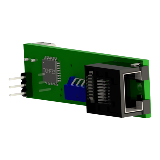
- Page 1 ™ GSDA-CM-8 ASCII Communications Module User Manual User Manual Number: GSDA-CM-8 IronHorse GSDA-CM-8 User Manual – 1st Ed. Rev. A – 10/15/19 Page 1...
-
Page 2: Warning
Automationdirect.com® Incorporated. AutomationDirect retains the exclusive rights to all information included in this document. Publication History User Manual Publication History Issue Date Description First Edition 06/25/19 Initial release 1st Edition Rev. A 10/15/19 Minor revisions IronHorse GSDA-CM-8 User Manual – 1st Ed. Rev. A – 10/15/19 Page 2... -
Page 3: Table Of Contents
GSDA-CM-8 User Manual Overview ........ -
Page 4: Gsda-Cm-8 User Manual Overview
GSDA-CM-8 User Manual Overview Overview of this Publication The IronHorse GSDA-CM-8 User Manual describes the installation, configuration, and methods of operation of the GSDA-CM-8 ASCII Communications Module. All information contained in this manual is intended to be correct. However, information and data in this manual are subject to change without notice. -
Page 5: Gsda-Cm-8 Overview
Manual” mode for the drive. If the GSDA-CM-8 option card is in the Auto/Manual master slot and the GSDA-CM-8 jumper is in place for Auto mode, then the drive will also be in Auto mode. The GSD8 drive will then accept the target speed setting from the option card. Whether or not the GSD8 drive follows the GSDA-CM-8 analog input source depends on the analog input routing option on the serial card. - Page 6 SLOT 500 SLOT 200 (Install GSDA-CM-8 in slot 500 only) The GSDA-CM-8 is configured with default values that provide a checkout procedure to verify that the network is connected correctly and functioning. See the GSDA-CM-8 Item (Parameter) Table for further details.
-
Page 7: Using The Analog Input
Using the Analog Input The GSDA-CM-8 has a built-in analog to digital converter. This input may be used in lieu of a digital pick-up signal or to control Target speed, current program, or frequency generator output frequency. To use this input with a potentiometer source, connect a pot wiper to Pin 7 of the serial interface port, pot high to the +5V terminal, pot low to the Common terminal. - Page 8 By selecting the voltage source type, the GSD8 drive will track a rapidly changing analog input signal. The GSDA-CM-8 samples the analog input signal at the rate of 50 milliseconds. Intended primarily as a feedback signal, replacing an encoder feedback signal or a leader signal when in a master/follower application;...
- Page 9 • Analog Source Signal Maximum Value Minimum Value: “Minimum Value” refers to the lowest scaled value produced by the GSDA-CM-8, A to D converter when the analog source signal is at the lowest value. • For a potentiometer source signal, minimum value occurs with the potentiometer wiper at the closest position to the potentiometer terminal connected to the GSDA-CM-8, signal common;...
- Page 10 The actual conversion value of 512.29 cannot be produced by the A/D converter and is rounded down to 512. IronHorse GSDA-CM-8 User Manual – 1st Ed. Rev. A – 10/15/19 Page 10...
- Page 11 Analog Source Signal Connection The drawing below of the female RJ45 “modular” connector on the GSDA-CM-8 describes the pins that are used for analog input as well as the other pins on the connector. RJ45 Pin Signal Description RS232 Rx (Receive data)
-
Page 12: User-Assignable Output
Parameter 5030 = 1, 2, or 3 The GSDA-CM-8 has a frequency generator output that can be used as the leader signal to drive a network of followers. The GSDA-CM-8 that is generating this signal can even follow its own generator’s output. -
Page 13: Communications And Networking
• A software package that allows the computer to communicate with a selected com port. You will need to configure the software to allow it to communicate with the GSDA-CM-8 Serial Card. These products ship with their serial communications port set at 9600 baud, 8 data bits, and 1 stop bit. -
Page 14: Rs-232 And Rs-422/485 Connections To The Rj45 Modular Jack
RJ45 pins 1 and 8 should remain disconnected. When connecting a computer with an RS-232 port to an GSDA-CM-8 unit, not all of the available wires have to be used. If a port with a DB-9 (9 pins) connector is used, then make the following connections: •... -
Page 15: Software - Data Format
Item 20: Network Address. This can be a value from 01 to 99. If you have more than one GSDA-CM-8 on your network, you should set each unit to a unique address. Commands sent to address “00” will be acted upon by every GSDA-CM-8 on your network. - Page 16 “0001”, “001”, “01”, and “1” are all the same to the GSDA-CM-8. NOTE: All addresses must be two digits so 01 through 09 must have a leading zero. All messages sent to the GSDA-CM-8 follow a common structure, or “format”. The command message format is shown below: <command><address>,<”command stuff”><CR>...
-
Page 17: Direct Commands From A Computer/Plc
Direct Commands from a Computer/PLC The GSDA-CM-8 is configured with six commands (commands must be in upper case). These commands are discussed below and on the following pages: Set Target Speed (or Time in seconds) Description Allows the setting of a desired speed (or Process Time) SP<address>,<speed><CR>... - Page 18 Response if unsuccessful N<CR> NOTE: In the response from the GSDA-CM-8, <value> and <dec. pt.> will ALWAYS be transmitted as 4 digits, with leading zeros present. <dec. pt.> is the location of the displayed decimal point for that variable. Its values are: xxxx. = 0, xxx.x = 1, xx.xx = 2, xxxx = 4.
-
Page 19: Gsda-Cm-8 Software Parameters (Items)
15 = S1 Falling / 16 - S2 Falling / 16 1 = Force Zero Speed Power-Up Target Speed 2 = Force Power-up Value 3 = Use Previous Target Speed IronHorse GSDA-CM-8 User Manual – 1st Ed. Rev. A – 10/15/19 Page 19... - Page 20 S2 Input Configuration 4 = Inhibit - S2 High 5 = Inhibit - S2 Low 6 = Jog - S2 High 7 = Jog - S2 Low IronHorse GSDA-CM-8 User Manual – 1st Ed. Rev. A – 10/15/19 Page 20...
- Page 21 Alarm1 Output Style & Reset 2 = Constant & Manual Reset Mode 3 = Pulsed & Auto Reset 4 = Pulsed & Manual Reset Pulse ON Time 1-3600 Seconds IronHorse GSDA-CM-8 User Manual – 1st Ed. Rev. A – 10/15/19 Page 21...
- Page 22 1 = Reserved 2 = Use Slot 100 Alarm1 Output Alarm2 Output Routing 3 = Use Slot 200 Alarm1 Output 4 = Use Slot 500 Alarm1 Output IronHorse GSDA-CM-8 User Manual – 1st Ed. Rev. A – 10/15/19 Page 22...
- Page 23 S1 (Main) Pickup is Stalled S2 (Leader) Pickup is Stopped (Valid Only in "Follower Mode") Jog Function Activated Inhibit Function Activated E-Stop Function Activated IronHorse GSDA-CM-8 User Manual – 1st Ed. Rev. A – 10/15/19 Page 23...
- Page 24 2041 Speed = 20mA Minimum Setting) Eng Units 1042 4mA Output Trim -600 - +600 2042 1043 20mA Output Trim -600 - +600 2043 IronHorse GSDA-CM-8 User Manual – 1st Ed. Rev. A – 10/15/19 Page 24...
- Page 25 5 = Main Tach Signal 6 = Leader Tach Signal 1 = Potentiometer GSDA-CM-8 - Analog Input 5041 2 = 0 to +5 Source Type 3 = 4 to 20 IronHorse GSDA-CM-8 User Manual – 1st Ed. Rev. A – 10/15/19 Page 25...
-
Page 26: Gsda-Cm-8 Software Item (Parameter) Descriptions
This number represents the base model number for the product. The model Model Number code for the GSDA-CM-8 card is 51. In this manual, where appropriate, the “Drive” in which this GSDA-CM-8 card is installed is called the GSD8 Drive. - Page 27 This sets the lowest output frequency from the frequency generator. Note: if Frequency Generator MIN you are using mode 1 of Item 30 of the GSDA-CM-8 then this Item is controlled by Item 42 of the GSDA-CM-8. This sets the highest output frequency from the frequency generator. Note: if...
-
Page 28: Automationdirect Plc Example Programs For Gsd8 Dc Drive
Complete when received the delimiter character 0x0D OR after a timeout of 100 ms String Structure On Success, Set bit StrmInSuccess On Error, Set bit StrmInError Page 1 $Main IronHorse GSDA-CM-8 User Manual – 1st Ed. Rev. A – 10/15/19 Page 28... - Page 29 StrmInSuccess STRCLEAR Clear Strings Start String SS0 - SS1 Number of Strings to Clear StrmInError RSTR Reset Range StrmOutSuccess Start SetTargetSPCmmd Page 2 $Main IronHorse GSDA-CM-8 User Manual – 1st Ed. Rev. A – 10/15/19 Page 29...
- Page 30 Serial Port CPU-485 In Progress SendCommand1.InProgress mand String StringCommand Complete SendCommand1.Complete Enable Termination Code 1 Termination Code 2 Byte Swap Option No Byte Swap No Null Conversion Productivity100 IronHorse GSDA-CM-8 User Manual – 1st Ed. Rev. A – 10/15/19 Page 30...
- Page 31 Counter of No reply. Increasing values for the counter means the command was not accepted ReceiveC Compare SIMPLE COUNTER ommand String2.E Preset Value Current Value CNTNo.Current 1.Success qual Done CNTNo.Done Count Up CNTNo.D Reset Productivity1000 IronHorse GSDA-CM-8 User Manual – 1st Ed. Rev. A – 10/15/19 Page 31...
- Page 32 Reset of bits involved. If there is no increment in any of the counters, the string command is not correctly formed ReceiveC ommand 1.Success SendCommand SendCommand1.Compl ReceiveCommand1.Suc cess PACK STRING Source Length Decimal Digits Destination ReceiveCommand1.Destination Enable "" Align Left Productivity100 IronHorse GSDA-CM-8 User Manual – 1st Ed. Rev. A – 10/15/19 Page 32...
- Page 33 Literature Number: LT181 Drawing Number: A-5-4166B IronHorse GSDA-CM-8 User Manual – 1st Ed. Rev. A – 10/15/19 Page 33...
Need help?
Do you have a question about the GSDA-CM-8 and is the answer not in the manual?
Questions and answers