Table of Contents
Advertisement
Quick Links
V2021.01.07
PRODUCT MANUAL
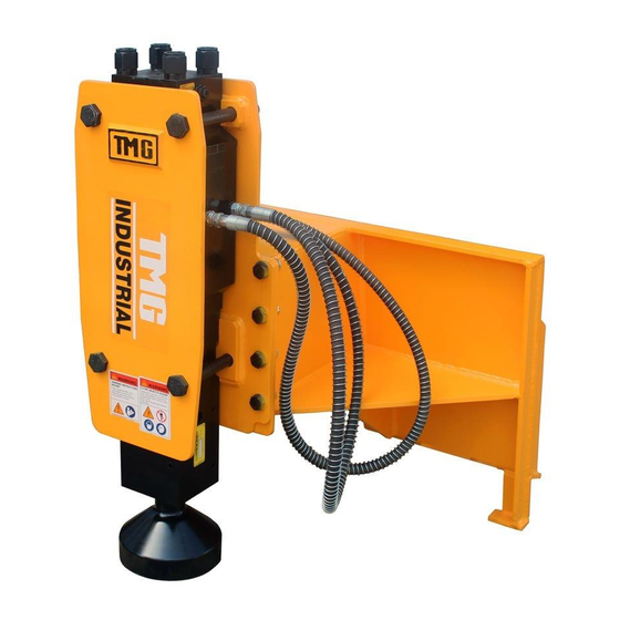
Skid Steer Hydraulic Post Driver
MODEL:TMG-PD700S
Please read the product manual completely before assembly
Check against the parts list to make sure all parts are received
Wear proper safety goggles or other protective gears while in assembly
Missing parts or questions on assembly?
Please call: 1-877-761-2819 or email: cs@tmgindustrial.com
Do not return the product to dealer, they are not equipped to handle your requests
WWW.TMGINDUSTRIAL.COM
Toll Free:1-877-761-2819
Advertisement
Table of Contents

Related Manuals for TMG TMG-PD700S


Summary of Contents for TMG TMG-PD700S
- Page 1 V2021.01.07 PRODUCT MANUAL Skid Steer Hydraulic Post Driver MODEL:TMG-PD700S Please read the product manual completely before assembly Check against the parts list to make sure all parts are received Wear proper safety goggles or other protective gears while in assembly Missing parts or questions on assembly? Please call: 1-877-761-2819 or email: cs@tmgindustrial.com...
-
Page 2: Table Of Contents
CONTENTS OPERATING MANUAL 1. Safety Precautions ……………………………………………………………….......……..03 2. Standard Specifications ……………………………………………………………………….....05 3. Construction & Main Parts ……………………………………………………………………....06 4. Post driver Tools …………………………………………………………………………………....07 5. Preparation for Installation & Operation ………………………………………………….......09 6. Operation ……………………………………………………………………………………......10 7. Repair & Inspection ………………………………………………………………………......12 8. Inspection & Charging (Back Head) …………………………………………………......15 9. -
Page 3: Safety Precautions
1. Safety Precautions 1.1 Safety Precautions 1) This manual contains safety, operation, and routine maintenance instructions. It does not contain service disassembly instructions. If needed, complete service disassembly and assembly instructions are contained in the manual, which can be ordered from your Hydraulic Attachments -Post driver hammer authorized and certified dealer. - Page 4 g) Do not operate the Post driver hammer unless thoroughly trained or under the supervision of an instructor. h) Become familiar with the carrier controls before operating the carrier and the Post driver hammer. i) While learning to operator the Post driver hammer and carrier, do so at a slow pace. If necessary, set the carrier mode selector to the slow position.
-
Page 5: Standard Specifications
2. Standard Specifications 2.1 Standard Specifications Model Unit FD700S Operating weight Working Flow Rate liter /min 36-60 Oil Relief Pressure kg/cm2 Working Pressure kg/cm2 110-140 Impact rate 500-900 Chisel Diameter ¢68 Hose Diameter inch Back head pressure kg/cm2 • The above specifications are subject to change without prior notice for the quality WWW.TMGINDUSTRIAL.COM P5/23 Toll Free:1-877-761-2819... -
Page 6: Construction & Main Parts
3. Construction & Main Parts 3.1 Inner Valve Type Through bolt Front head, cylinder and back head of Post driver hammer body are tightly fixed with four through bolts. Back head Back head Through bolt This contains cushion chamber charged with... -
Page 7: Post Driver Tools
4. Post driver Tools 4.1 Tool Replacement 1) Remove the stop pin and the tool pin with a 330mm-long steel bar. When reassembling, align the groove in the tool and the tool pin hole and insert the tool pins. 2) Reverse disassembly procedures to install a replacement too. - Page 8 4.2 Greasing Manual Greasing System Apply grease to grease nipple on front head every 3 hours. Adapt grease interval and amounts to tool wear rates and working conditions. NOTICE Tool shank must be well lubricated before installed in front head. While greasing, hydraulic breaker must be upright against the tool.
-
Page 9: Preparation For Installation & Operation
5. Preparation for Installation & Operation 5.1 Hydraulic pipe lines for exclusive use. Operation of the post driver hammer requires installation of hydraulic pipe lines for exclusive use of the post driver hammer. As hydraulic pipe lines vary depending on base machines, the service engineer must first check hydraulic pressure, oil capacity, pressure loss and other conditions of the base machine before installing hydraulic pipe lines. -
Page 10: Operation
6. Operation 6.1 Operation method 1. Pre-drill a pilot hole if the soil conditions are rocky, frozen, or too difficult to simply drive the post into the ground. 2. Requires another person to position the pile. This person will set the pile at the desired location and grasp the pile securely. - Page 11 4) Do not allow the Post driver hammer to fall to drive the pile. Dropping the Post driver hammer onto the pile will apply excessive force to the Post driver hammer or the base machine, causing damage to many parts of the Post driver hammer and the base machine. Let the driver press the pile to drive it into the ground.
-
Page 12: Repair & Inspection
7. Repair & inspection 7.1 Periodic Maintenance (Every 100 hours) 1) Remove the tool and all grease from the bushing Do not use a pressure washer, steam or solvents as they damage the seals. Chuck for chips or cracks inside the housing and on the bushing surfaces. Cracks and chips could indicate that : ①... - Page 13 7.2 Daily Post driver hammer inspection Before starting operation, be sure to inspect the Post driver hammer referring to the following table. Inspection Item Inspection Point Remedy Looseness, missing and Through bolts. Check looseness. damage bolts and nuts Bracket mounting bolts. Retighten securely.
- Page 14 Tool, resulting in damage. When the gap is found to be over 9mm, replace the Tool bush together with the Tool. Change Timing of the Tool Bush (mm) ■ Model Wear Limit(mm) TMG-PD700S WWW.TMGINDUSTRIAL.COM P14/23 Toll Free:1-877-761-2819...
-
Page 15: Inspection & Charging (Back Head)
8. Inspection and Charging Nitrogen (N2) Gas at the Back-Head 8.1 N2-Gas Charging Tools to the Back-Head ① N2-Gas Cylinder ② Adaptor Nut ③ Adaptor ④ Hose ⑤ Gas Charging Kit WWW.TMGINDUSTRIAL.COM P15/23 Toll Free:1-877-761-2819... - Page 16 8.2 Inspection of N2-Gas in the Back-Head 1) Make sure that the cap and the valve of the gas charging kit(⑤) are fully tightened. Screw the gas charging kit(⑤) into the charging valve of the Back-Head after removing the plug. 2) At this time the handle must be short to prevent the gas from coming out.
-
Page 17: Troubleshooting Guide
9 TROUBLESHOOTING GUIDE 9.1 Problems in operation If the Post driver hammer does not work or blow frequency and blow get worse, check following troubleshooting. And then inspect according to the following order. Symptom Cause Required action 1.Excessive back head gas pressure 1.Re-adjust nitrogen gas pressure 2.Stop valve (s) closed 2.Open Stop Valve... - Page 18 9.2 Gas Leakage WWW.TMGINDUSTRIAL.COM P18/23 Toll Free:1-877-761-2819...
- Page 19 9.3 Oil Leakage Even if oil is leaking, there is no use to replacing parts at all times check the following points listed in the chart below. The user can check the (☞) marked points before calling dealer. WWW.TMGINDUSTRIAL.COM P19/23 Toll Free:1-877-761-2819...
-
Page 20: Customer's Report
10. CUSTOMERS’ REPORT 10.1 Delivery and Installation Card This is report is for checking that Post driver hammer is correctly delivered and equipped on machine Distributor should correctly draw up this. This is report must be drawn up in typewritten and Informed within 7 days after the date When delivered Post driver hammer to customer. -
Page 21: Exploded Drawings And Past List
MAIN EXPLODED DRAWINGS Main Parts List Ref# Description Ref# Description Quick connect Side bolt M27*230 Bracket welder(FR) Nuts 41MM Hydraulic power unit Bracket welder(RR) Stopper Hex.Bolt M20*55 Hoses 1/2inch,2.4m Stopper Hex.Nut Post driver chisel WWW.TMGINDUSTRIAL.COM P21/23 Toll Free:1-877-761-2819... - Page 22 HYDRAULIC POWER UNIT EXPLODED DRAWINGS WWW.TMGINDUSTRIAL.COM P22/23 Toll Free:1-877-761-2819...
- Page 23 Hydraulic Power Unit Parts List Ref# Description Ref# Description Back head Valve plug Charging valve assembly O-ring O-ring O-ring Cylinder Valve sleeve Seal retainer Front Head O-ring Grease nipple Plug Tool pin Gas seal Φ68 Stop pin U-packing(Step seal) SPNS 68 Stop pin ( bush) O-ring Ring bush...
Need help?
Do you have a question about the TMG-PD700S and is the answer not in the manual?
Questions and answers