
Related Manuals for Honeywell GF505


Summary of Contents for Honeywell GF505
- Page 1 GF505 & GF510 Fire Alarm Control Panels Manual Document 53164 Rev: B5 6/12/2018 ECN: 18-253...
- Page 2 (especially Limit-D2-2016 in bedrooms), smoking in bed, and violent explosions (caused by escaping gas, improper storage of flammable materials, etc.). GF505 & GF510 Manual — P/N 53164:B5 6/12/2018...
- Page 3 Acclimate®, eVance®, FocalPoint®, Gamewell-FCI®, FAAST Fire Alarm Aspiration Sensing Technology®, Honeywell®, Intelligent FAAST®, SmartScan®, SWIFT®, Velociti®, and E3 Series® are registered trademarks of Honeywell International Inc. Microsoft® and Windows® are registered trademarks of the Microsoft Corporation. Chrome™ and Google™ are trademarks of Google Inc. Firefox® is a registered trademark of The Mozilla Foundation.
- Page 4 Your suggestion for how to correct/improve documentation Send email messages to: FireSystems.TechPubs@honeywell.com Please note this email address is for documentation feedback only. If you have any technical issues, please contact Technical Services. GF505 & GF510 Manual — P/N 53164:B5 6/12/2018...
-
Page 5: Table Of Contents
3.2: Initial Power-up .......................................45 3.3: Programming Screens Description ..................................45 3.4: Programming and Passwords...................................45 3.5: Master Programming Level .....................................46 3.5.1: Input Zones ......................................46 3.5.2: NAC (Notification Appliance Circuit) ..............................56 Enabled ........................................56 NAC Coding ......................................56 GF505 & GF510 Manual — P/N 53164:B5 6/12/2018... - Page 6 4.17.4: Waterflow Retard Timer..................................91 4.17.5: Alarm Verification (None or One Minute) ............................91 4.18: Walktest..........................................91 4.19: Read Status ........................................92 4.19.1: Input Zones ......................................92 4.19.2: NAC ........................................92 4.19.3: Relays .........................................93 4.19.4: System Settings....................................93 4.19.5: Timers .........................................93 GF505 & GF510 Manual — P/N 53164:B5 6/12/2018...
- Page 7 Appendix D: Wire Requirements..........................115 D.1: GF-505 NAC Wiring ....................................115 D.2: GF-510 NAC Wiring ....................................116 Appendix E: Default Programming ..........................117 Index ....................................118 GF505 & GF510 Fire Alarm Control Panel Operating Instructions ..............................121 GF505 & GF510 Manual — P/N 53164:B5 6/12/2018...
- Page 8 UL 864, 9th Edition. Operation of this product with products not tested for UL 864, 9th Edition has not been evaluated. Such oper- ation requires the approval of the local Authority Having Jurisdiction (AHJ). GF505 & GF510 Manual — P/N 53164:B5 6/12/2018...
- Page 9 GF505 Main Circuit Board ms-5udlayout.wmf GF505 & GF510 Manual — P/N 53164:B5 6/12/2018...
- Page 10 GF510D Series Main Circuit Board ms-10udlayout.wmf GF505 & GF510 Manual — P/N 53164:B5 6/12/2018...
- Page 11 Doc. #53386 ANN-BUS - TB3 IPDACT Internet Communicator Doc. #53109 J8 & J9 Telephone Connections 4XTMF J4 & J5 Reverse Polarity Module Local PC Battery Connector - J12 FCI-CHG-120 Charger Doc. #52459 GF505 & GF510 Manual — P/N 53164:B5 6/12/2018...
-
Page 12: Section 1: Product Description
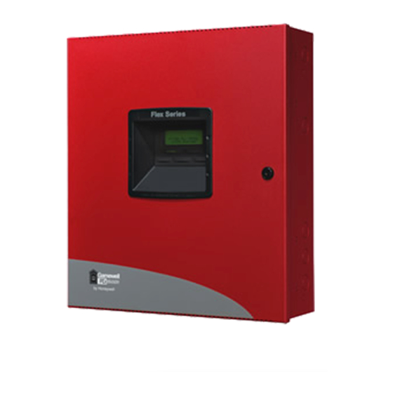
Section 1: Product Description The GF505 is a five zone FACP (Fire Alarm Control Panel) and the GF510 is a ten zone FACP. The information in this manual refers to both the GF505 and GF510 unless otherwise specified. The combination control and digital communicator panels provide reliable fire signaling protection for small to medium sized commercial, industrial and institutional buildings. -
Page 13: Specifications
Supervised, nonpower-limited Maximum Charger Capacity: 26 Amp Hour battery for GF505 & GF510 [two 18 Amp Hour batteries can be housed in FACP cabinet. Larger batteries require a separate battery box such as the BB-55F and the FCI-CHG-120 Battery Charger.]... - Page 14 All connections must be in conduit, less than 20 ft. (610 cm) in length in the same room. GF505 & GF510 Manual — P/N 53164:B5 6/12/2018...
- Page 15 Product Description The following figure illustrates the maximum current that is possible for each major panel output circuit and the total current available from the FACP with the FLPS-7 power supply. This applies to the GF505 & GF510. Special Application 0.5 amp max...
-
Page 16: Controls And Indicators
For tone burst or touchtone type formats: discern proper Ack and Kissoff tone(s). The frequency and time duration of the tone(s) varies with the transmission format. The control panel will adjust accordingly. • Communicate in the following formats: Ademco Contact ID SIA-DCS-8 SIA-DCS-20 GF505 & GF510 Manual — P/N 53164:B5 6/12/2018... -
Page 17: Components
The CAC-5X Module can be used to convert the Style B (Class B) Initiating Device Circuits to Style D (Class A) and Style Y (Class B) Notification Appliance Circuits to Style Z (Class A). The module connects to J2 on the GF505 and to J7 on the GF510. Note that two Class A Converter modules are required for the 10 zone panel. -
Page 18: Telephone Requirements And Warnings
68 rules and requirements adopted by ACTA. This equipment is designed to be connected to the telephone network or premises wiring using a compliant RJ31X male modular plug and compatible modular jack that is also compliant. GF505 & GF510 Manual — P/N 53164:B5 6/12/2018... -
Page 19: Section 2: Installation
(refer to Figure 2.4 on page 22) mounting slots GF505 Backbox Figure 2.1 Chassis Mounting in Backbox GF505 & GF510 Manual — P/N 53164:B5 6/12/2018... - Page 20 Hinge Slot for optional holes on top of box. Dress Panel Mounting slots for optional Trim Ring Semi- Flush mounting hole Hinge Slot for optional Dress Panel Figure 2.2 Cabinet Dimensions GF505 & GF510 Manual — P/N 53164:B5 6/12/2018...
-
Page 21: Operating Power
BATTERIES CONTAINS SULFURIC ACID WHICH CAN CAUSE SEVERE BURNS TO THE SKIN AND EYES AND CAN DESTROY FABRICS. IF CONTACT IS MADE WITH SULFURIC ACID, IMMEDIATELY FLUSH THE SKIN OR EYES WITH WATER FOR 15 MINUTES AND SEEK IMMEDIATE MEDICAL ATTENTION. GF505 & GF510 Manual — P/N 53164:B5 6/12/2018... -
Page 22: Input Circuits
2.3 Input Circuits The GF505 has five IDCs (Initiating Device Circuits) and the GF510 has ten IDCs. Each circuit is compatible with System Sensor’s i smoke detectors which generate a maintenance signal when the detector becomes dirty and a separate supervisory ‘freeze’ signal when ambient temperature falls below the detector rating of approximately 45 F. - Page 23 Resettable 24 VDC 4-wire smoke Dummy load all unused detector power circuits - 4.7 KΩ, ½ watt heat detectors (500 mA maximum) resistor (P/N: 71245) Figure 2.5 IDC Connections GF505 & GF510 Manual — P/N 53164:B5 6/12/2018...
-
Page 24: Output Circuits
Total current drawn from the four Style Y (Class B) Notification Appliance Circuits as well as other DC power outputs cannot exceed 7.0 amps for the GF505 & GF510 [3.0 amps maximum per NAC] powered by the FLPS-7 power supply (refer to “Power Supply Calcu- lations”... -
Page 25: 2: Special Application Dc Power Output Connections
Figure 2.7 NAC Connections 2.4.2 Special Application DC Power Output Connections Special Application Resettable and Nonresettable 24 VDC power is available on the GF505 and GF510 control panel. Special Application 4-Wire Smoke Detector Power (500 mA) -
Page 26: 3: Relays - Programmable
2.4.3 Relays - Programmable The GF505 and GF510 control panels provide a factory default programmed alarm relay, fail-safe trouble relay and supervisory relay. Each relay can be programmed to activate for other conditions (refer to “Relays” on page 59). Each Form-C relay is rated for 2 amps @ 30VDC (resistive) and 0.5 amps @ 30 VAC (resistive). -
Page 27: Power-Limited Wiring Requirements
(Class 2) Power-limited Circuits (Class 2) CAC-5X CAC-5X AC Power 4XTMF Nonpower- earth limited ground Circuit Nonpower- limited Circuit Power-limited Circuit (Class 2) GF510 FACP Figure 2.11 Typical UL Power-limited Wiring Requirements GF505 & GF510 Manual — P/N 53164:B5 6/12/2018... -
Page 28: Digital Communicator
RJ31X Jack Secondary Primary removed during phone line PH-2 phone line male plug insertion PH-1 7 foot cable Modular female MCBL-7 connectors (ordered separately) Male plug connectors Figure 2.13 Wiring Phone Jacks GF505 & GF510 Manual — P/N 53164:B5 6/12/2018... -
Page 29: Installation Of Optional Modules
(Class B) Notification Appliance Circuits to Style Z (Class A). The module plugs into connector J2 which is located at the top left of the GF505 and GF510 main circuit board and J7 which is located at the top center of the GF510. Note that two CAC-5X modules are required to convert all NACs and IDCs on the GF510 to Class A circuits. -
Page 30: 2: 4Xtmf Option Module
For proper 4XTM operation, the output relays must be programmed for the factory default settings: Alarm Relay 1, Trouble Relay 2 and Supervisory Relay 3. When the installation has been completed, connect the wiring to the modules as indicated in the following sections. Test system for proper operation. GF505 & GF510 Manual — P/N 53164:B5 6/12/2018... -
Page 31: 4Xtmf Transmitter Module Installation
Note: This illustration shows the installation of the Option Module on the 5-zone panel. The module is installed in the same location on the 10-zone panel. Figure 2.16 4XTMF Option Module Connection to GF505 4XTMF Transmitter Module Installation The 4XTMF provides a supervised output for a local energy municipal box transmitter in addition to alarm and trouble reverse polarity. -
Page 32: 3: Ann-Sec Option Card
Secure the ANN-SEC to the circuit board with the supplied screw. connector to J13 on main circuit board ANN-SEC FACP Circuit Board standoff and screw Figure 2.18 Installing the ANN-SEC Option Card GF505 & GF510 Manual — P/N 53164:B5 6/12/2018... -
Page 33: Ann-Bus Devices
938 ft. 1,493 ft. 2,362 ft. Table 2.2 Wiring Distances The following formulas were used to generate the wire distance chart: Maximum Resistance (Ohms) 6.0 Volts Total Worst Case Current Draw (amps) GF505 & GF510 Manual — P/N 53164:B5 6/12/2018... -
Page 34: Wiring Configuration
Figure 2.19 illustrates the wiring between the FACP’s Primary ANN-BUS and ANN-BUS devices. FACP Primary ANN-BUS ANN-BUS and power wiring are supervised and power-limited GFANN-80 Figure 2.19 FACP wiring to ANN-BUS Device on Primary ANN-BUS GF505 & GF510 Manual — P/N 53164:B5 6/12/2018... - Page 35 FACP’s Secondary ANN-BUS, via the ANN-SEC option card, and ANN-BUS devices. ANN-SEC - + A B FACP Secondary ANN-BUS ANN-BUS and power wiring are supervised and power-limited GFANN-80 Figure 2.20 FACP wiring to ANN-BUS Device on Secondary ANN-BUS via ANN-SEC GF505 & GF510 Manual — P/N 53164:B5 6/12/2018...
-
Page 36: Powering Ann-Bus Devices From Auxiliary Power Supply
NOTE: address (ID Number) DIP switches on some devices may have more than 5 switch positions. Unless otherwise specified in the documentation supplied with each device, switch positions 6 and above must be set to OFF. Address Switch 5 Switch 4 Switch 3 Switch 2 Switch 1 not valid GF505 & GF510 Manual — P/N 53164:B5 6/12/2018... -
Page 37: 3: Gfann-80 Remote Fire Annunciator
The ANN-SB80KIT(-R/-B/-W) is an available mounting kit for the ANN-80 annunciator. The kit comes with a surface backbox and sur- face wedge for angled viewing. The two pieces can be used separately or can be stacked together. GF505 & GF510 Manual — P/N 53164:B5 6/12/2018... -
Page 38: Wiring Gfann-80 To Facp
1 (-) & 2 (+). Make certain to observe proper polarity. After all connections are made, remove extra wire from inside of annunciator by dressing it neatly through wire channel, with any excess wire pushed back through hole into electrical box. GF505 & GF510 Manual — P/N 53164:B5 6/12/2018... -
Page 39: 4: Gfann-Led Annunciator Module
4 3 2 1 ANN-BUS and power wiring are supervised and power-limited GFANN-80 Figure 2.22 GFANN-80 Wiring to FACP The following table shows the GFANN-80 connections to the GF505/GF510. GF505/GF510 (TB3) GFANN-80 (TB1) Terminal 4 GND (-) Terminal 1 (-) -
Page 40: Gfann-Led Board Layout And Connection To Facp
2 amps @ 30 VDC (resistive) 0.5 amps @ 30 VAC (resistive) • Operating Temperature: 32 F to 120 F (0 C to 49 • For indoor use in a dry location only GF505 & GF510 Manual — P/N 53164:B5 6/12/2018... -
Page 41: Mounting/Installation
ANN-MBRLY mounting hooks through mounting bracket GFANN-RLY mounting slots ROME Series Installation using ANN-MBRLY mounting bracket mounting holes mounting holes GFANN-RLY on mounting holes ANN-MBRLY mounting bracket Figure 2.24 GFANN-RLY Mounting Options GF505 & GF510 Manual — P/N 53164:B5 6/12/2018... -
Page 42: Gfann-Rly Board Layout And Connection To Facp
Figure 2.25 illustrates the GFANN-RLY board wiring connections to the FACP. ANN-BUS (ID#) Address DIP switch GFANN-RLY FACP -24 VDC +24 VDC Primary ANN-BUS Figure 2.25 GFANN-RLY Board Layout and Connection to FACP GF505 & GF510 Manual — P/N 53164:B5 6/12/2018... -
Page 43: Section 3: Programming
Superv Supervisory device 3.1 User Programming The GF505/GF510 FACP is completely field programmable using the panel keypad and requires no special software skills. CAUTION: FIRE PROTECTION ENABLED WHILE PROGRAMMING THE FACP, THE FIRE PROTECTION CAPABILITIES OF THE CONTROL PANEL ARE ENABLED. - Page 44 ‘ESC’ key. If the Reset key is pressed or power is lost before exiting Programming mode, all data just entered will be lost. GF505 & GF510 Manual — P/N 53164:B5 6/12/2018...
-
Page 45: Initial Power-Up
Entering the Master level password (default 00000) will cause the following screen to appear: PROGRAMMING 1=INPUT ZONES 2=NACS 3=RELAYS If the Maintenance level password (default 11111) is entered, the following screen will appear: PROGRAMMING 1=INPUT ZONES 2=HISTORY 3=WALKTEST GF505 & GF510 Manual — P/N 53164:B5 6/12/2018... -
Page 46: Master Programming Level
Input Zone Screen #1 Pressing the down arrow key will display additional screens for Input Zones 4 through 5 in the GF505 or Input Zones 4 through 10 in the GF510. To program a specific zone, press the number key corresponding to the desired zone while viewing one of the Input Zone screens. - Page 47 The 3=VERIFICATION control panel LCD will display the zone which has been disabled and FACP will turn on the Trouble LED. Edit Input Zone Screen #2 GF505 & GF510 Manual — P/N 53164:B5 6/12/2018...
- Page 48 While viewing any Zone Type screen, select the type of zone being programmed by pressing the corresponding keyboard number key. The display will return to Edit Input Zone Screen #2 and indicate the selection next to the Type option. GF505 & GF510 Manual — P/N 53164:B5 6/12/2018...
- Page 49 Verification feature to be enabled. Do not use the verification feature if a mix of smoke detectors and normally open contact devices are connected to the same zone. GF505 & GF510 Manual — P/N 53164:B5 6/12/2018...
- Page 50 Pressing 1 while viewing Edit Input Zone Screen #3 will display the following screen: INPUT ZONE # 1=PAS/PRE-SIG DELAY PAS/PRE-SIG DELAY NO DELAY 1=NO DELAY Edit Input Zone Screen #3 2=PRE-SIGNAL DELAY 3=PAS DELAY PAS/Pre-Signal Delay Screen GF505 & GF510 Manual — P/N 53164:B5 6/12/2018...
- Page 51 Note that the alarm relay and communicator will respond to the initial alarm immediately. To enable the Pre-signal feature, press 2 while viewing PAS/Pre-Signal Screen. Refer to “Presignal” on page 90. GF505 & GF510 Manual — P/N 53164:B5 6/12/2018...
- Page 52 15 seconds plus a programmable time of up to 3 minutes. To enable the PAS feature, press 3 while viewing the PAS/Pre- Signal Screen. This option is available only for circuits programmed as smoke detector circuits. Refer to “Positive Alarm Sequence” on page 90. GF505 & GF510 Manual — P/N 53164:B5 6/12/2018...
- Page 53 Each press of the 1 key will toggle the display 1=FREEZE SUPV. NO 2=ACC MSG # between Freeze Supv. Yes and No. The factory default setting is No Freeze Supervision. Edit Input Zone Screen #4 GF505 & GF510 Manual — P/N 53164:B5 6/12/2018...
- Page 54 Adjective and Noun Screens. The new screens will list custom Adjectives and Nouns which have been pro- 2=STANDARD NOUN 3=CUSTOM ADJECTIVE grammed into the control panel by the user utilizing the PK-CD programming kit. These descriptors are 4=CUSTOM NOUN selected as described in the previous sections. Adjective/Noun Screen GF505 & GF510 Manual — P/N 53164:B5 6/12/2018...
- Page 55 Enter key to store the information. The display will return to the Edit Input Zone Screen #4, displaying the new information at the bottom of the screen. GF505 & GF510 Manual — P/N 53164:B5 6/12/2018...
-
Page 56: 2: Nac (Notification Appliance Circuit)
Two Stage 3 Minutes or 5 Minutes - refer to “Two Stage Operation” on page 57 for a description of this feature • Synchronized output for System Sensor, Wheelock, Gentex, Faraday or Amseco - Refer to “Synchronized NAC Operation” on page 57 for additional information GF505 & GF510 Manual — P/N 53164:B5 6/12/2018... - Page 57 This is particularly critical when activating strobes which must be synchronized to avoid random activation and a potential hazard or confusion. The FACP can be programmed to operate with a variety of manufacturer’s devices. GF505 & GF510 Manual — P/N 53164:B5 6/12/2018...
-
Page 58: Silence
NAC Screen #2 will cause a screen to be displayed with the options 1=No Silence Inhibit and 2=1 Min. Silence Inhibit. Pressing 1 will disable the Silence Inhibit feature while pressing 2 will enable a 1 minute Silence Inhibit for the selected Output. GF505 & GF510 Manual — P/N 53164:B5 6/12/2018... -
Page 59: 3: Relays
System Setup Screen #1. The following screen will be displayed: 1=TIMERS 2=BANNER 3=TIME-DATE TIMERS TIMERS System Setup Screen #1 1=PAS DELAY 1=AC LOSS DELAY 2=PRE SIGNAL 3=WATERFLW DELAY Timer Screen #2 Timer Screen #1 GF505 & GF510 Manual — P/N 53164:B5 6/12/2018... - Page 60 NOTE: Upon the loss of AC power at the control panel, relays programmed for AC Loss will transfer immediately, regardless of the AC Loss Delay setting. If no troubles other than AC Loss exist in the panel, the System Trouble relay will delay activation for the duration of the AC Loss Delay setting. GF505 & GF510 Manual — P/N 53164:B5 6/12/2018...
-
Page 61: Banner
Time-Date Screen which will show the new time entry. If an error is made while entering a digit, press the CLR key to delete the entire entry and beginning again. GF505 & GF510 Manual — P/N 53164:B5 6/12/2018... -
Page 62: Trouble Reminder
Disable No and Chrgr Disable Yes. 3.5.5 Option Modules Options available for the FACP include annunciators, printer connection for acquiring hardcopy printouts PROGRAMMING of panel data and onboard DACT. 1=SYSTEM SETUP 2=OPTION MODULES 3=HISTORY Programming Screen #2 GF505 & GF510 Manual — P/N 53164:B5 6/12/2018... -
Page 63: Ann-Bus
Pressing 2 while viewing ANN-BUS screen #2 will display the following screen: ANN-80 OPTIONS ANN-80 OPTIONS 1=SIL BTN ENABLE 1=PIEZO ENABLE 2=RST BTN ENABLE 2=LOCK ENABLE 3=DRL BTN ENABLE 3=ACK BTN ENABLE ANN-80 Options Screen #2 ANN-80 Options Screen #1 GF505 & GF510 Manual — P/N 53164:B5 6/12/2018... -
Page 64: Ann-Rly Options Screen
ANN-BUS, press 2 while viewing ANN-BUS Screen #3 so that the display reads ANN-SEC ENABLE YES. Each press of the 2 key will cause the display to toggle between ANN-SEC ENABLE YES and ANN-SEC ENABLE NO. The factory default setting is ANN-SEC ENABLE NO. GF505 & GF510 Manual — P/N 53164:B5 6/12/2018... -
Page 65: Onboard Dact
3 while viewing Onboard DACT Screen 1 will cause the following screens to be displayed: 1=PRIM PHONE 2=SCND PHONE CENTRAL STATION 3=CENTRAL STATION CENTRAL STATION 1=REPORTING 1=PRIMARY Onboard DACT Screen #1 2=REPORT STYLE 2=SECONDARY 3=CALL LIMIT FIRST AVAILABLE Central Station Screen #2 Central Station Screen #1 GF505 & GF510 Manual — P/N 53164:B5 6/12/2018... - Page 66 To enable the DACT for reporting FACP activity to the central station, press 1 while viewing Central Station Screen #1 so the display reads Reporting Yes. Each press of the 1 key will toggle the display between Reporting Yes and Reporting No. GF505 & GF510 Manual — P/N 53164:B5 6/12/2018...
- Page 67 Press 1 to have all reports transmitted to the central station secondary phone number as a backup only if the primary phone line fails, 2 to transmit all reports to both the primary and secondary phone numbers all of the time, or 3 to send reports to the first available phone number. GF505 & GF510 Manual — P/N 53164:B5 6/12/2018...
- Page 68 CENTRAL STATION CENTRAL STATION 1=TEST TIME INT 1=PHONE NUMBER 1=COMM FORMAT 2=ACCOUNT CODE 0000 ADEMCO CONTACT ID 3=24HR T TIME 0000 2=EVENT CODES Primary/Secondary Screen #2 Primary/Secondary Screen #1 Primary/Secondary Screen #3 GF505 & GF510 Manual — P/N 53164:B5 6/12/2018...
- Page 69 The test report sent to the Central Station phone number may be sent once every 6, 8, 12 or 24 hours. Select the desired Test Time Inter- val by pressing the corresponding digit in the screens shown above. GF505 & GF510 Manual — P/N 53164:B5 6/12/2018...
- Page 70 Program the supplied 4-digit account code using 0 - 9 and A - F keys. Enter the first digit, then press the right arrow key to move the cursor to the right, one position. Repeat the process until all digits are entered. GF505 & GF510 Manual — P/N 53164:B5 6/12/2018...
- Page 71 Use the 24 Hour Test Time screen to program the time that the DACT will transmit the 24 Hour Test to the Central Station. A flashing cursor will appear in the lower left corner of the screen. Enter a four digit number representing the test time using military time (0000 = midnight and 2359 = 11:59PM). GF505 & GF510 Manual — P/N 53164:B5 6/12/2018...
- Page 72 9. Enter 9 followed by D for a three second pause, or E for a five second pause then the phone number followed by an F to indicate the end of the number. GF505 & GF510 Manual — P/N 53164:B5 6/12/2018...
- Page 73 Screen Selection Communication Format Description ADEMCO CONTACT ID Contact ID, DTMF, 1400/2300 ACK SIA-DCS-8 Security Industry Association, 8 messages per call SIA-DCS-20 Security Industry Association, 20 messages per call Table 3.2 Communication Formats GF505 & GF510 Manual — P/N 53164:B5 6/12/2018...
- Page 74 The following tables list all of the Events and their default Event Codes for the Ademco Contact ID and SIA-DCS Communication For- mats. NOTE: A detector freeze condition will be reported as a Supervisory Event Code. GF505 & GF510 Manual — P/N 53164:B5 6/12/2018...
- Page 75 Primary # Upload Successful Primary # Download Successful Primary # Upload/Download Failed Primary # Voice EVAC Fault Primary # Power Supply Sync Fault Table 3.4 Ademco Contact ID Primary # Event Codes GF505 & GF510 Manual — P/N 53164:B5 6/12/2018...
- Page 76 Secondary # Upload Successful Secondary # Download Successful Secondary # Upload/Download Failed Secondary # Voice EVAC Fault Secondary # Power Supply Sync fault Table 3.5 Ademco Contact ID Secondary # Event Codes GF505 & GF510 Manual — P/N 53164:B5 6/12/2018...
- Page 77 Primary # Zone 9 Dirty Primary # Zone 10 Dirty FT10 FJ10 Primary # Earth Fault ET38 ER38 Primary # Low Battery Fault Primary # No Battery Fault Table 3.6 SIA-DCS Primary # Event Codes GF505 & GF510 Manual — P/N 53164:B5 6/12/2018...
- Page 78 Primary # Upload/Download Request Primary # Upload Successful Primary # Download Successful Primary # Upload/Download Failed Primary # Voice EVAC Fault Primary # Power Supply Sync Fault Table 3.6 SIA-DCS Primary # Event Codes (Continued) GF505 & GF510 Manual — P/N 53164:B5 6/12/2018...
- Page 79 Secondary # Zone 9 Dirty Secondary # Zone 10 Dirty FT10 FJ10 Secondary # Earth Fault ET38 ER38 Secondary # Low Battery Fault Secondary # No Battery Fault Table 3.7 SIA-DCS Secondary # Event Codes GF505 & GF510 Manual — P/N 53164:B5 6/12/2018...
- Page 80 FACP and PC. The Service Terminal selection provides the means for entering these parameters. Onboard DACT Screen #2 GF505 & GF510 Manual — P/N 53164:B5 6/12/2018...
-
Page 81: 6: History
While displaying the View Events screen, press 1 to view all events, 2 to view only alarms, or 3 to view other events. Use the up and down arrow keys to scroll through all of the displayed events. GF505 & GF510 Manual — P/N 53164:B5 6/12/2018... -
Page 82: Erase History
3=PASSWORD CHANGE SYSTEM CHANGE Programming Screen #3 PROCEED? 1=YES 2=NO Pressing 1 will cause the control panel to carry out the selected clear option. Pressing 2 will prevent programming from being cleared. GF505 & GF510 Manual — P/N 53164:B5 6/12/2018... -
Page 83: Printer/Pc
Password Change Screen The new five digit password must be re-entered to accept the change. The display will then return to the initial Password Change Screen. GF505 & GF510 Manual — P/N 53164:B5 6/12/2018 GF505 & GF510 Manual — P/N 53164:B5... -
Page 84: Maintenance Programming Level
Zone Select Screen Pressing the down arrow key will display additional Zones (Zones 4 - 5 for GF505 and Zones 4 - 10 for GF510). Select the number cor- responding to the desired zone. A screen will appear which will allow enabling or disabling of the selected zone, as illustrated in the fol-... -
Page 85: 3=Walktest
To change between 12 hour and 24 hour format, press 3 while viewing the Time and Date screen. Each press of the 3 key will toggle the display between 12 HR and 24 HR format. GF505 & GF510 Manual — P/N 53164:B5 6/12/2018... -
Page 86: Section 4: Operating Instructions
With no alarms or troubles in the system, the display message is System All Normal along with the current time and date as shown below. To set the time and date, refer to the appropriate section in this manual. SYSTEM ALL NORMAL 10:00A 060718 GF505 & GF510 Manual — P/N 53164:B5 6/12/2018... -
Page 87: Trouble Operation
The piezo sounder produces a steady output as opposed to a pulsed output • The Fire Alarm LED flashes 1 second On and 1 second Off • The LCD displays Alarm along with the device name, type, adjective/noun, associated zones and time/date GF505 & GF510 Manual — P/N 53164:B5 6/12/2018... -
Page 88: Supervisory Operation
Communicate the process monitor condition to the Central Station (if the default event code has been changed from 000 to a reportable event code) • Relays programmed for process monitoring will be activated GF505 & GF510 Manual — P/N 53164:B5 6/12/2018... -
Page 89: Hazard/Tornado Condition Operation
NOTE: To ensure that the system is functioning properly, the FACP will perform a freeze check five minutes after the panel is reset, followed by a maintenance check. If there is no freeze or maintenance condition, the panel will continue to monitor for freeze conditions every hour and maintenance conditions every four hours. GF505 & GF510 Manual — P/N 53164:B5 6/12/2018... -
Page 90: Time Functions: Real-Time Clock
This option, if selected, prevents the Alarm Silenced and Reset keys from functioning for 60 seconds following an alarm. A new alarm during the initial 60 second period will not cause the timer to restart with a new 60 seconds. Silence Inhibit operation requires the approval of the local Authority Having Jurisdiction. GF505 & GF510 Manual — P/N 53164:B5 6/12/2018... -
Page 91: 2: Autosilence Timer
IDCs and all main circuit board NACs are monitored for fault conditions during Walktest mode. When an open condition occurs on an IDC, the FACP will activate all enabled NACs during an audible Walktest and remain activated until the open condition is cleared. GF505 & GF510 Manual — P/N 53164:B5 6/12/2018... -
Page 92: Read Status
3=ZONE 3 Pressing the down arrow key will allow the selection of Zones 4-5 for the GF505 and Zones 4-10 for the GF510. The operator selects the zone which is to be viewed by pressing the number corresponding to the desired zone in each screen. For exam-... -
Page 93: 3: Relays
4.19.8 Print To print program data or control panel status, press 2 while viewing Read Status Screen #3. The following screen will be displayed: PRINT 1=HISTORY 2=WALKTEST LOG 3=EXIT PRINTING GF505 & GF510 Manual — P/N 53164:B5 6/12/2018... -
Page 94: 9: Ann-Bus
TCH TNE SECONDARY TCH TNE 3=SUPERV PHONE LINE The second and third lines of this screen indicate that both the Primary and Secondary phone lines have been configured for touchtone dialing operation. GF505 & GF510 Manual — P/N 53164:B5 6/12/2018... -
Page 95: 12: Service Terminal
READ STATUS 1=CENTRAL STATION SERVICE TERMINAL 2=PHONE LINES 3=SERVICE TERMINAL RING COUNT Read Status Screen #4 Service Terminal Screen The Ring Count is displayed as the first item in the Service Terminal Screen. GF505 & GF510 Manual — P/N 53164:B5 6/12/2018... -
Page 96: Section 5: Central Station Communications
Fire drill AC Zone fault Earth Battery Telephone line Notification Appliance Circuits Communication Annunciator trouble System off normal 24 Hour Test (lowest priority) GF505 & GF510 Manual — P/N 53164:B5 6/12/2018... - Page 97 Transmittal Priorities Central Station Communications The table below shows UL listed receivers which are compatible with the GF505 and GF510. Format SIA-DCS-8 SIA-DCS-20 Ademco Contact ID ...
-
Page 98: Section 6: Local/Remote Site Upload/Download
The first time that the control panel is contacted, a secret code is loaded in by a Service Terminal. Future upload or download requests cause verification of the secret code by the control panel before processing of data is allowed. If the secret code is not verified, the con- trol panel will terminate the request. GF505 & GF510 Manual — P/N 53164:B5 6/12/2018... -
Page 99: 1: Security Features
Central Station information. These blocks of data are protected from partial programming due to faulty phone connec- tions, line noise and other errors. This prevents the panel from being confused due to a wrong phone number, account code, test time and most critical formatting errors. GF505 & GF510 Manual — P/N 53164:B5 6/12/2018... -
Page 100: Section 7: Power Supply Calculations
Calculation Column 2 - The primary supply current load that the control panel must support during a fire alarm condition, with AC power applied. Calculation Column 3 - The standby current drawn from the batteries in a non-fire alarm condition during a loss of AC power. GF505 & GF510 Manual — P/N 53164:B5 6/12/2018... - Page 101 Refer to the Device Compatibility Document for standby current. Enter the number of IDCs used minus one. Must use compatible listed Power Supervision Relay. Total current draw listed above cannot exceed 7.25 for the GF505 and 7.28 for the GF510. GF505 & GF510 Manual — P/N 53164:B5 6/12/2018...
-
Page 102: Calculating The Battery Size
Select batteries that meet or exceed the total ampere hours calculated in Table 7.4. The control panel can charge batteries in the 7 AH to 26 AH range. The control panel cabinet is capable of housing batteries up to 18 AH. GF505 & GF510 Manual — P/N 53164:B5 6/12/2018... -
Page 103: Appendix A: Ademco Contact Id Format Event Code Descriptions
Burglary Communication Communication General Protective Loop 24 Hour Sensor EVENT MESSAGE Medical Alarms - 100 100 Medical EMERG - Personal Emergency - # 101 Pendant Transmitter EMERG - Personal Embergency - # GF505 & GF510 Manual — P/N 53164:B5 6/12/2018... - Page 104 ALARM - Water Leakage - # 155 Foil break ALARM - Foil Break - # 156 Day trouble ALARM - Day Trouble - # 157 Low bottled gas level ALARM - Low Gas Level - # GF505 & GF510 Manual — P/N 53164:B5 6/12/2018...
- Page 105 334 Repeater failure TROUBLE - Repeater Failure - # 335 Local printer paper out TROUBLE - Printer Paper Out 336 Local printer failure TROUBLE - Local Printer Communication Troubles - 350 and 360 GF505 & GF510 Manual — P/N 53164:B5 6/12/2018...
- Page 106 421 Access denied ACCESS - Access Denied - User # (restore not used) 422 Access report by user ACCESS - Access Gained - User # (restore not used) System Disables - 500 and 510 GF505 & GF510 Manual — P/N 53164:B5 6/12/2018...
- Page 107 (restore not applicable) 606 Listen-in to follow LISTEN - Listen-in Active (restore not applicable) 607 Walk test mode TEST - Walk Test Mode 608 System abnormal test TEST - System Abnormal Test GF505 & GF510 Manual — P/N 53164:B5 6/12/2018...
-
Page 108: Appendix B: Nfpa Standard-Specific Requirements
Appendix B: NFPA Standard-Specific Requirements The GF505/GF510 has been designed for use in commercial, industrial and institutional applications and meets the requirements for ser- vice under the National Fire Protection Association (NFPA) Standards outlined in this Appendix. The minimum system components... - Page 109 NFPA Standard-Specific Requirements The following figure illustrates an example of Central Station/Remote Station Reporting using a 411UD. The relay contacts from the GF505/GF510 may be used to trip any dialer UL listed for Central Station/Remote Station Reporting Services. 411UD Channel1...
- Page 110 Reference the 411UD Manual for additional information Program the 411UD for slave operation The GF505/GF510 must be programmed for AC Loss Reporting Delay This prevents the immediate transmission of a trouble on the loss of AC power All connections between the control panel and the 411UD must be in conduit, less than 20 feet (610 cm) in length, in the same room Any zone of the 411UD can be wired to function as alarm, trouble or supervisory.
- Page 111 NFPA 72 Remote Station Protective Signaling System Notes: Cut Jumper JP30 on the GF505/GF510 main circuit board to supervise placement of the 4XTMF module. Refer to“4XTMF Transmitter Module Installation” on page 31 for detailed information. RS82 Remote Station Receiver UL listed.
- Page 112 NFPA 72 Proprietary Protective Signaling System. Potter Electric Model EFT-C has not been tested for UL 864 9th Edition and is for use in retrofit applications only. Figure B.4 Proprietary Protective Signaling System GF505 & GF510 Manual — P/N 53164:B5 6/12/2018...
-
Page 113: B.1: Central Station/Remote Station Transmitter: Connection To Facp Dry Contacts
NO and C contacts as indicated in the illustration. Fire Alarm Control Panel Figure B.5 FACP Dry Contacts Connection to Central Station/Remote Station Transmitter GF505 & GF510 Manual — P/N 53164:B5 6/12/2018... -
Page 114: Appendix C: Facp With Keltron
Note: Cut TBL jumper on 4XTMF module to send alarm/trouble signal from the same pair or terminals. Fire Alarm Control Panel (terminal blocks are not shown in their actual positions in order to clarify wiring connections) Figure C.1 Keltron Wiring GF505 & GF510 Manual — P/N 53164:B5 6/12/2018... -
Page 115: Appendix D: Wire Requirements
NAC voltage with the entire load at the end of the circuit. Further distances can be achieved by performing a point to point voltage calculation that more accurately reflects the specific devices used and how they are dispersed on the circuit. GF505 & GF510 Manual — P/N 53164:B5 6/12/2018... -
Page 116: D.2: Gf-510 Nac Wiring
NAC voltage with the entire load at the end of the circuit. Further distances can be achieved by performing a point to point voltage calculation that more accurately reflects the specific devices used and how they are dispersed on the circuit. GF505 & GF510 Manual — P/N 53164:B5 6/12/2018... -
Page 117: Appendix E: Default Programming
Printer Offline Timer Central Station Secondary Phone Number ANN-BUS Enabled Central Station Secondary Test Time 2:00 ANN-LED Piezo Enabled Central Station Seocndary Account Code 0000 ANN-80 Piezo Enabled Service Terminal Ring Count GF505 & GF510 Manual — P/N 53164:B5 6/12/2018... -
Page 118: Index
Initiating Device Circuit 12 baud rate 83 backbox 17 Class A 29 buttons Downloading 98 In-Line resistor see also control buttons 12 Drill 12 IDC combination circuit 24 Input Zones 46 installation 19 GF505 & GF510 Manual — P/N 53164:B5 6/12/2018... - Page 119 Positive Alarm Sequence 52 End-of-Line resistor 13 see also Transmitter module 17 power 14 maximum current 13 Ring Count 81 primary 21 silence inhibit 58 Ringer Equivalence Number 18 GF505 & GF510 Manual — P/N 53164:B5 6/12/2018...
- Page 120 Timers 59 Transmittal Priorities 96 transmitter module 17 operation 31 specifications 31 Transmitter option module placement supervision 30 Trouble 87 trouble piezo pulse rate 16 trouble call limit 43 Trouble Input Auxiliary 14 GF505 & GF510 Manual — P/N 53164:B5 6/12/2018...
-
Page 121: Gf505 & Gf510 Fire Alarm Control Panel Operating Instructions
Gamewell-FCI Service Representative Every indicator/LED should be on, LCD shows all pixels on, piezo sounder beeps. Name: _____________________________________ For more information, refer to the GF505 & GF510 Series Manual, Document #53164. It is kept in the following location: Company: __________________________________ _______________________________________________________... - Page 123 Return Material Authorization form. The replacement part shall come from Manufacturer's stock and may be new or refurbished. THE FOREGOING IS DISTRIBUTOR'S SOLE AND EXCLUSIVE REMEDY IN THE EVENT OF A WARRANTY CLAIM. Warn-HL-08-2009.fm GF505 & GF510 Manual — P/N 53164:B5 6/12/2018...
- Page 124 Honeywell Gamewell-FCI 12 Clintonville Road Northford, CT 06472-1610 203.484.7161 53164 | B5 | 06-18 www.gamewell-fci.com ©2018 Honeywell International Inc.
Need help?
Do you have a question about the GF505 and is the answer not in the manual?
Questions and answers