Table of Contents
Advertisement
Quick Links
Installation and operating instructions
GAS FRY-TOP FOR
PROFESSIONAL USE
FTLD-85GS FTRD-85GS
FTLD-87GS FTLRD-87GS FTRD-87GS
FTLD-89GS FTLRD-89GS FTRD-89GS
FTLD-95GS FTRD-95GS
FTLD-99GS FTLRD-99GS FTRD-99GS
Model LIBR.ISTR.FTD-G
Edition date 18/01/2021
31020 San Vendemiano
Code 563047000
Review 1
Language English
LOTUS S.p.A.
Via Calmaor, 46
+39 0438 778020
+39 0438 778277
Translation of the original instructions
Advertisement
Table of Contents

Subscribe to Our Youtube Channel
Related Manuals for Lotus FTLD-85GS


Summary of Contents for Lotus FTLD-85GS
- Page 1 Installation and operating instructions GAS FRY-TOP FOR PROFESSIONAL USE FTLD-85GS FTRD-85GS FTLD-87GS FTLRD-87GS FTRD-87GS FTLD-89GS FTLRD-89GS FTRD-89GS FTLD-95GS FTRD-95GS FTLD-99GS FTLRD-99GS FTRD-99GS Model LIBR.ISTR.FTD-G Code 563047000 Review 1 Edition date 18/01/2021 Language English LOTUS S.p.A. Via Calmaor, 46 31020 San Vendemiano...
-
Page 2: Table Of Contents
Contents Contents INTRODUCTION ......................... Installation drawing ........................Components..........................GENERAL INFORMATION......................Declaration of compliance......................User information, RAEE Directive on waste electrical and electronic equipment ......Technical data table ........................INSTALLATION........................... Delivery checks ..........................Removing the packaging ......................Mechanical installation ......................... Electrical/gas connections ......................Water connection and drainage.................... -
Page 3: Introduction
INTRODUCTION 1 INTRODUCTION Installation drawing FIG. 1 FTD...G Translation of the original instructions... - Page 4 INTRODUCTION AIR INPUT MODEL A (mm) B (mm) C (mm) D (mm) E (mm) (cm²) FT…D-85G 597,5 77,3 ≥ 150 FT…D-87G 597,5 77,3 ≥ 220 FT…D-89G 597,5 87,1 ≥ 300 FT…D-95G 77,3 ≥ 345 FT…D-99G 87,1 ≥ 490 B Electrical connection C Gas connection D Water connection R 1/2"M E Water drain R 1"M...
-
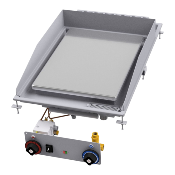
Page 5: Components
INTRODUCTION Components FIG. A 1 Valve knob 2 Dashboard bracket 3 Piezoelectric 4 Valve 5 Gas pipes 6 Extends drainage 7 Pilot 8 Ignition spark plug 9 Injector 10 Bracket 11 Fat collection pan Translation of the original instructions... - Page 6 INTRODUCTION FIG. B 1 Bracket 2 Pilot light nozzle 3 Ignition spark plug 4 Extends drainage WIRING DIAGRAM FTDG 1 Power supply terminal board 2 Power button 3-4 Ignition control unit Translation of the original instructions...
-
Page 7: General Information
GENERAL INFORMATION 2 GENERAL INFORMATION Declaration of compliance The manufacturer declares that the appliances comply with the requirements of the regulation GAR 2016/426 for the gas part and directive 2014/30/EU,2014/35/EU for the electrical part. Installation must be performed in compliance with current regulations, especially with regard to ventilation of the premises and the exhaust gas evacuation system. -
Page 8: User Information, Raee Directive On Waste Electrical And Electronic Equipment
GENERAL INFORMATION User information, RAEE Directive on waste electrical and electronic equipment With regard to the regulatory framework of reference of the European Community, we remind the user of the following: · Used AAE (Electrical and Electronic Equipment) products must be collected separately ·... -
Page 9: Installation
INSTALLATION 3 INSTALLATION Delivery checks On delivery, it is important to check the following: · External conditions of the packaging · The general status of the equipment · The conformity of the model with the information in the technical data plate and the instruction manual ·... - Page 10 INSTALLATION Note The ID plate is located in the compartment inside the door for appliances with compartments, or on the left side for appliances with an oven or a top. A second plate with the model and serial number is located inside the dashboard and a third is included with the certificate of conformity.
- Page 11 INSTALLATION The appliance must be connected to an equipotential system. The connecting screw is located on the rear of the appliance and is marked by the yellow symbol above it. Warning The manufacturer is not liable for and does not indemnify damages caused by incorrect ...
- Page 12 INSTALLATION Disposition for conversion and installation for other types of gas: Our appliances are tested and set for liquid gas or natural gas (see attached data plate). Conversion or adaptation to another type of gas must be performed by a specialist technician. The nozzles for the various types of gas are contained in a bag included in the supply and are marked in hundredths of mm (see "Burners"...
- Page 13 INSTALLATION 1 Windproof fume stack (fig.3) - Extractor hood (fig.4) 2 Servo system "B11" type appliances are supplied on request with a hood or a hood and windproof fume stack to be assembled and delivered separately. Translation of the original instructions...
-
Page 14: Water Connection And Drainage
INSTALLATION Water connection and drainage To limit the temperature on the floor, we recommend connecting the drop-in to the water supply (see installation drawing and technical data table). It is also advisable to install a shut-off valve upstream of the appliance. -
Page 15: Burners Technical Data Table (Itgb)
BURNERS TECHNICAL DATA TABLE (ITGB) 4 BURNERS TECHNICAL DATA TABLE (ITGB) Burners technical data table Burner technical data table FTDG 12.68 kWh/KG 12.87 kWh/KG 9.45 kWh/m3st. BUTANE PROPANE METHANE H 30 mbar 37 mbar 20 mbar FT…D-85GS ... -
Page 16: Instructions For Use
INSTRUCTIONS FOR USE 5 INSTRUCTIONS FOR USE General information This appliance must only be used for its expressly intended purpose for cooking or heating food. Any other use is considered improper. The appliance is also intended for industrial use and must only be used by personnel trained for use and aware of the risks that the hot element entails. -
Page 17: Switching The Appliance Off
INSTRUCTIONS FOR USE Switching the appliance off · Press and turn the knob to position "0". This control blocks the gas supply to both the main burner and the pilot burner Observations and advice · In the case of appliances with two cooking zones, it is possible to set different temperatures on the two halves of the plate, or use only one half. -
Page 18: Maintenance
MAINTENANCE 6 MAINTENANCE Routine When using the appliance over time, it is essential to perform regular maintenance to ensure safe operation. We therefore recommend stipulating a service contract. Caution Maintenance must only be performed by specialist personnel in compliance with current ... -
Page 19: Spare Parts
MAINTENANCE Warning After conversion to another type of gas, update the technical data plate to indicate the type of gas for which the appliance has been converted. Spare parts It is possible to replace parts such as the valve, the piezoelectric or the ignition control unit (depending on the type of appliance) or the gas pipes easily and quickly. -
Page 20: Cleaning
CLEANING 7 CLEANING Routine cleaning Caution The use of flammable fluids to clean the appliance is forbidden To ensure hygiene and the durability of the appliance, perform external cleaning on a regular basis, taking care not to damage the cables and the electrical connections. Before starting cleaning, disconnect the appliance from the power supply.
Need help?
Do you have a question about the FTLD-85GS and is the answer not in the manual?
Questions and answers