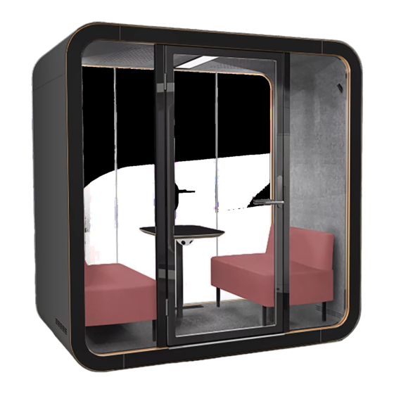
Framery Q Installation Instructions Manual
Hide thumbs
Also See for Q:
- Maintenance instructions manual (64 pages) ,
- Installation instructions manual (38 pages)

Subscribe to Our Youtube Channel
Related Manuals for Framery Q


Summary of Contents for Framery Q
- Page 1 English Framery Q (UL) Meeting Maggie Version 5.0 Tampere, Finland 21.6.2022 Installation instructions...
-
Page 3: Table Of Contents
Framery Q (UL) Meeting Maggie Contents 1 Warranty checklist..................7 2 Important safety and product instructions..........8 2.1 Preface........................8 2.2 Product information....................8 2.3 Copyright.........................8 2.4 Manual contents..................... 8 2.5 Intended use......................8 2.5.1 Non-conventional use.................9 2.5.2 Ambient conditions for use.................9 2.6 Warning, information, and safety symbols in this manual........ - Page 4 Framery Q (UL) Meeting Maggie 7.2 Install the control panel (optional)................ 44 7.3 Install the front glasses..................48 7.4 Install the upper and lower frames..............53 7.5 Install the booking system bracket (optional)............55 8 Back frames and glasses................. 63 8.1 Install the side frames (back)................63 8.2 Install the lower frame..................66...
- Page 5 Framery Q (UL) Meeting Maggie 16.3 Install the roof body covers................136 16.4 Install the wall body covers................138 17 Finish the installation................140 18 Moving the pod (optional)..............142...
- Page 6 Framery Q (UL) Meeting Maggie...
-
Page 7: Warranty Checklist
For the product warranty to be valid: Fill this checklist and send it to Framery after pod installation. Take a photo or scan the filled list and send it to Framery at warranty@frameryacoustics.com. Leave the completed list inside the pod. -
Page 8: Important Safety And Product Instructions
• Installation instructions 2.5 Intended use The Framery Q is a pod intended for short term indoor commercial and household use by one to four (1-4) people at a time. Warning: WARNING –To reduce the risk of burns, fire, electric shock, or injury to persons: Use this product only for its intended use as described in the user instructions. -
Page 9: Non-Conventional Use
Framery Q (UL) Meeting Maggie 2.5.1 Non-conventional use Any use or maintenance of the product that is not specifically allowed in the installation, maintenance, troubleshooting or user instructions is prohibited, including the following: • Installation, maintenance or disassembly of the pod without reading and understanding the instructions for those actions •... -
Page 10: Main Safety Risks Related To The Installation, Maintenance, Disassembly, And Use Of The Product
Framery Q (UL) Meeting Maggie 2.7 Main safety risks related to the installation, maintenance, disassembly, and use of the product 2.7.1 Installation, maintenance, and disassembly WARNING! To reduce the risk of burns, fire, electric shock, or injury to persons, obey the following: Use cut resistant safety gloves during the installation, maintenance, or disassembly of the product. -
Page 11: Fire Safety
Do not connect any extension cords to the power outlet(s) of the product. 2.7.3 Fire safety The fire load for the Framery Q is approx. 5200 MJ. WARNING! To reduce the risk of burns, fire, electric shock, or injury to persons,... -
Page 12: Use
Risk of injury! Keep hands and other body parts clear of the side edges of the table when raising or lowering the electrically adjustable table top. This applies to all Framery pods with an electric adjustable table. Do not use the product if the surrounding conditions are in any way hazardous;... -
Page 13: Moving The Product On Casters (Optional)
Framery Q (UL) Meeting Maggie Do not use the product if the ventilation is not functioning. Do not use the product if the ventilation channels are blocked. Keep the ventilation channels free of lint, hair, and the like. Do not use the pod if you notice any defects in the electrical equipment or if the product is not working properly. -
Page 14: Location Of Product Markings
Framery Q (UL) Meeting Maggie 2.9 Location of Product Markings Position Label Label text Framery This furnishing has not been evaluated for flammability or cigarette ignition resistance L'inflammabilité ou la résistance à l'allumage d'une cigarette n'a pas été évaluée pour cette garniture Installation instructions info@frameryacoustics.com... - Page 15 Made in Finland / Fabriqué en Finlande Interior options: • FRAMERY Q EMPTY • FRAMERY Q MEETING MAGGIE • FRAMERY Q WORKING WITH PAL • FRAMERY Q FLOW Attention! Always connect the product correctly to a grounded socket to avoid danger for fire or electrical shocks.
- Page 16 Framery Q (UL) Meeting Maggie Position Label Label text SN / N° de série: WARNING - Risk of fire and shock Use only ‘SJT’ type ‘16’ AWG cord AVERTISSEMENT - Risque d’incendie et de choc électrique, utiliser uniquement un cordon d'alimentation ‘SJT’...
-
Page 17: Installation Requirements
Framery Q (UL) Meeting Maggie 3 Installation requirements 3.1 Tools and accessories Figure 1: Tools and accessories needed for installation and maintenance Note: Use a white rubber mallet to prevent leaving marks on the body covers. Note: Use a plastic chisel to remove the body covers. -
Page 18: Main Dimensions
Framery Q (UL) Meeting Maggie Note: Use a separate piece of carpet in the door installation. Note: Use a lint-free cloth to clean the pod. Note: Use a mild alcohol-based cleaning solution to clean the pod. Tip: Use glass washing liquid as a lubricant to help install the seal. -
Page 19: Operating Space
Framery Q (UL) Meeting Maggie Figure 3: Installation space measurements 3.4 Operating space Make sure that the pod has enough space for the air to circulate correctly. Note: If the pod is placed in a corridor or a passageway, make sure that, when open, the pod door does not obstruct the required egress path. -
Page 20: Seismic Anchoring Requirements
Framery Q (UL) Meeting Maggie 3.5 Seismic anchoring requirements Note: When installing the product, take into consideration all local laws, rules and regulations concerning seismic anchoring and seismic safety. For installations in the U.S., in buildings located in Seismic Design Categories A and B, anchoring to the floor is optional. -
Page 21: Floor
Framery Q (UL) Meeting Maggie 4 Floor 4.1 Install the casters (optional) Lay the floor modules down on the side. If the delivery includes the optional casters, install the casters with 6.3x14 screws (4 pcs each). Lay the floor modules down on the floor. -
Page 22: Prepare The Acoustic Panel
Framery Q (UL) Meeting Maggie 4.2 Prepare the acoustic panel Remove one of the acoustic panels out of the floor. Cut the acoustic panel at the pre-cut line. Installation instructions info@frameryacoustics.com... -
Page 23: Connect The Floor Modules
Framery Q (UL) Meeting Maggie Place the smaller part of the acoustic panel against the back edge of the floor. 4.3 Connect the floor modules Lay the floor modules down at the intended final location. Leave approximately 0.5 m (1.8 ft) of empty space behind the floor modules. - Page 24 Framery Q (UL) Meeting Maggie Install guide pins (2 pcs) to the holes in one of the floor modules. Note: Make sure that the flat side of the guide pin goes into the mounting hole. Push the floor modules together.
- Page 25 Framery Q (UL) Meeting Maggie Install flanged M8x50 bolts (4 pcs) and M8 nuts (4 pcs). Unscrew the 4x20 screws (4 pcs) and remove the cover plates (4 pcs). Set the cover plates and screws aside. Installation instructions info@frameryacoustics.com...
- Page 26 Framery Q (UL) Meeting Maggie Install guide pins (4 pcs) to the holes on the front of the floor. Note: Make sure that the flat side of the guide pin goes into the mounting hole. Install the front lower frame to the front of the floor with M8x60 bolts (2 pcs) and M8 washers (2 pcs) at the small openings and with one M8x35 bolt and M8 washer at the center opening.
- Page 27 Framery Q (UL) Meeting Maggie Install guide pins (4 pcs) to the holes on the back of the floor. Note: Make sure that the flat side of the guide pin goes into the mounting hole. Install the back lower frame to the floor with M8x60 bolts (2 pcs) and M8 washers (2 pcs) at the small openings and with one M8x35 bolt and M8 washer at the center opening.
-
Page 28: Level The Floor
Framery Q (UL) Meeting Maggie 4.4 Level the floor Screw out the feet of the leveling screws (8 pcs) with a 4 mm hex key or 6 to 7 mm flathead screwdriver. Note: Make sure that the feet of the leveling screws are past the floor board. - Page 29 Framery Q (UL) Meeting Maggie Measure the floor module with a spirit level at six measuring points: • On top of the walls on the right-hand and left-hand sides • On the ABS strips at the edges of the floor modules Measure opposite points repeatedly and adjust the feet of the leveling screws gradually.
-
Page 30: Install The Wall Modules
Framery Q (UL) Meeting Maggie 5 Install the wall modules 5.1 Remove the wall cover panels Place the wall modules lengthwise against a wall. Unscrew the 4x30 screws (24 pcs) and remove the cover panels (4 pcs). Set the cover panels and screws aside. -
Page 31: Connect The Wall Modules To The Floor
Framery Q (UL) Meeting Maggie 5.2 Connect the wall modules to the floor Install the guide pins (4 pcs) to the mounting holes of the floor modules. Note: Make sure that the flat side of the guide pin goes into the mounting hole. - Page 32 Framery Q (UL) Meeting Maggie Install M8x35 bolts (4 pcs) and M8 washers (4 pcs) and tighten by hand. Note: Support the wall until it is secured with the bolts. Lift the other wall module into place. Note: Make sure that the "This side up" -sticker is on the top edge of the wall.
- Page 33 Framery Q (UL) Meeting Maggie Install M8x35 bolts (4 pcs) and M8 washers (4 pcs) and tighten by hand. Note: Support the wall until it is secured with the bolts. Installation instructions info@frameryacoustics.com...
-
Page 34: Roof
Framery Q (UL) Meeting Maggie 6 Roof 6.1 Connect the roof modules Unscrew the 4x20 screws (1 pcs each) and remove the roof cover plates (1 pcs each) from both roof modules. Set the cover plates and screws aside. Install the guide pins (2 pcs) to the mounting holes in one of the roof modules. - Page 35 Framery Q (UL) Meeting Maggie Push the roof modules together. Install flanged M8x50 bolts (4 pcs) and flanged M8 nuts (4 pcs). Installation instructions info@frameryacoustics.com...
- Page 36 Framery Q (UL) Meeting Maggie Install guide pins (4 pcs) to the mounting holes at the front edge of the roof. Note: Make sure that the flat side of the guide pin goes into the mounting hole. Push the back upper frame into place.
-
Page 37: Install The Roof
Framery Q (UL) Meeting Maggie Install with M8x60 bolts (2 pcs) and M8 washers (2 pcs) at the small openings and with one M8x35 bolt and M8 washer at the center opening. Note: Press the acoustic panel aside to reach the bolt holes. Make sure that you return the acoustic panel to its original position. - Page 38 Framery Q (UL) Meeting Maggie Install the guide pins (4 pcs) to the mounting holes of the wall modules. Note: Make sure that the guide pins are installed to the correct holes (closer to the wall felt). Note: Make sure that the flat side of the guide pin goes into the mounting hole.
- Page 39 Framery Q (UL) Meeting Maggie Install M8x35 bolts (8 pcs) and M8 washers (8 pcs) and tighten by hand. Installation instructions info@frameryacoustics.com...
-
Page 40: Front Frames And Glasses
Framery Q (UL) Meeting Maggie 7 Front frames and glasses 7.1 Install the side frames (front) Remove the front lower frame from the floor. Set the frame and bolts aside. Note: Leave the lower frame guide pins in place. Note: Press the acoustic panel aside to reach the bolt holes. Make sure that you return the acoustic panel to its original position. - Page 41 Framery Q (UL) Meeting Maggie Push the additional frame pieces (4 pcs) into place. Note: Make sure that the longer end of the additional frame piece is on the wall side. Install guide pins (8 pcs) to the holes on the front of the pod.
- Page 42 Framery Q (UL) Meeting Maggie Lift the left-hand side frame into place. Note: Support the frame until securely fastened. Install the left-hand frame with M8x35 bolts (2 pcs) and M8 washers (2 pcs), Installation instructions info@frameryacoustics.com...
- Page 43 Framery Q (UL) Meeting Maggie Lift the right-hand side frame into place. Note: Support the frame until securely fastened. Install the right-hand frame with M8x35 bolts (2 pcs) and M8 washers (2 pcs), Installation instructions info@frameryacoustics.com...
-
Page 44: Install The Control Panel (Optional)
Framery Q (UL) Meeting Maggie 7.2 Install the control panel (optional) Insert the rubber cover to the U-profile on top of the strike plate-side glass frame. Remove the plastic sticker over the holes for the control panel cord and screws on the strike plate-side glass frame. - Page 45 Framery Q (UL) Meeting Maggie Install the control panel bracket on the strike plate-side glass frame with M4x10 screws (2 pcs). Guide the control panel cord in through the hole in the middle of the strike plate-side glass frame and out through the U-profile on top of the strike plate-side glass frame.
- Page 46 Framery Q (UL) Meeting Maggie Install the rubber grommet into the hole in the control panel case. Install the magnets (2 pcs) behind the control panel with M4x10 screws (2 pcs). Use a hand tool to tighten the screws. Installation instructions...
- Page 47 Framery Q (UL) Meeting Maggie Connect the control panel cord to the panel. Install the control panel into the bracket. Note: The control panel attaches to the bracket with magnets. Note: Make sure that the cord is not caught between the magnets and the case.
-
Page 48: Install The Front Glasses
Framery Q (UL) Meeting Maggie 7.3 Install the front glasses Remove approximately 10 cm (4 in) of the protective film from the top and bottom of the aluminum frame of the lock-side glass. If installing the optional booking system bracket, install the rubber lead-through to the groove at the bottom of the aluminum frame. - Page 49 Framery Q (UL) Meeting Maggie If installing the optional booking system bracket, guide the customer supplied USB cord through the hole behind the strike plate and down out of the bottom of the aluminum frame. Note: Make sure that the USB A connector of the cord is at the bottom of the aluminum frame.
- Page 50 Framery Q (UL) Meeting Maggie Guide the strike plate-side glass into the grooves and slide it into place. Note: Make sure that the strike plate-side glass with the strike plate is on the correct side for the door handing. Note: If installing the optional booking system bracket, make sure that the USB cord is not damaged during the installation.
- Page 51 Framery Q (UL) Meeting Maggie Remove approximately 10 cm (4 in) of the protective film from the top and bottom of the aluminum frame of the hinge-side glass. Guide the hinge-side glass into the grooves and slide it into place.
- Page 52 Framery Q (UL) Meeting Maggie Measure the straightness of the hinge-side glass frame with a spirit level. Adjust if needed and install with M8x20 screws (2 pcs) and M8 washers (2 pcs). Use a hex key. Tighten the nylon screws (2 pcs each side) on the sides of the front of the pod with a flat-head screwdriver.
-
Page 53: Install The Upper And Lower Frames
Framery Q (UL) Meeting Maggie 10. Tighten M8x35 bolts (8 pcs on each side) with a spanner. 7.4 Install the upper and lower frames Install guide pins (8 pcs) to the holes on the front of the pod. Note: Make sure that the flat side of the guide pin goes into the mounting hole. - Page 54 Framery Q (UL) Meeting Maggie Install the upper frame with M8x60 bolts (2 pcs) and M8 washers (2 pcs) at the small openings and with one M8x35 bolt and M8 washer at the center opening. Note: Support the frame until securely fastened.
-
Page 55: Install The Booking System Bracket (Optional)
Framery Q (UL) Meeting Maggie 7.5 Install the booking system bracket (optional) Choose the small or large wooden back plate according to the size of the customer supplied tablet bracket. Unscrew the M5x25 Taptite screws (2 pcs) and remove the strike plate from the lock- side aluminum frame. - Page 56 Framery Q (UL) Meeting Maggie Cut the rubber grommet open vertically. Install the small rubber grommet onto the USB cord and insert the grommet into the hole in the lock-side glass. Note: Make sure that you leave enough cord on the out side to reach the customer supplied tablet.
- Page 57 Framery Q (UL) Meeting Maggie Install the large rubber grommet to the strike plate of the booking system bracket. Installation instructions info@frameryacoustics.com...
- Page 58 Framery Q (UL) Meeting Maggie Measure the correct place for the rubber spacer on the chosen wooden back plate and install with one 4x20 screw. Installation instructions info@frameryacoustics.com...
- Page 59 Framery Q (UL) Meeting Maggie Lead the USB cord through the grommet in the strike plate. Assemble the booking system bracket with one M6x30 screw and one M6 barrel nut. Hold the nut in the slot while tightening the screw.
- Page 60 Framery Q (UL) Meeting Maggie Pull the excess cord out of the slot in the strike plate. Install the strike plate with bracket assembly to the lock-side aluminum frame with the M5x25 Taptite screws (2 pcs) set aside earlier. Use a hand tool.
- Page 61 Framery Q (UL) Meeting Maggie 10. Feed the excess USB cord into the frame. Tip: You may need to pull on the cord at the opening near the floor to be able to adjust the length. 11. Install the plastic cover to the slot in the strike plate.
- Page 62 Framery Q (UL) Meeting Maggie 12. Guide the lower end of the USB cord into the groove at the side of the floor and along the top of the insulation board to the free space in the floor. Installation instructions...
-
Page 63: Back Frames And Glasses
Framery Q (UL) Meeting Maggie 8 Back frames and glasses 8.1 Install the side frames (back) Remove the back upper frame from the roof. Set the frame and bolts aside. Note: Leave the upper frame guide pins in place. Installation instructions... - Page 64 Framery Q (UL) Meeting Maggie Remove the back lower frame from the floor. Set the frame and bolts aside. Note: Leave the lower frame guide pins in place. Install guide pins (8 pcs) to the vacant holes on the back of the pod.
- Page 65 Framery Q (UL) Meeting Maggie Lift the left-hand side frame into place. Note: Support the frame until securely fastened. Install the left-hand frame with M8x35 bolts (2 pcs) and M8 washers (2 pcs). Installation instructions info@frameryacoustics.com...
-
Page 66: Install The Lower Frame
Framery Q (UL) Meeting Maggie Lift the right-hand side frame into place. Note: Support the frame until securely fastened. Install the right-hand frame with M8x35 bolts (2 pcs) and M8 washers (2 pcs). 8.2 Install the lower frame Install the lower frame to the floor with M8x60 bolts (2 pcs) and M8 washers (2 pcs) at the small openings and with one M8x35 bolt and M8 washer at the center opening. -
Page 67: Install The Back Glasses
Framery Q (UL) Meeting Maggie 8.3 Install the back glasses Lift one side glass into the groove in the lower frame and slide it into place. Note: Make sure that the glass sits at the inner edge of the groove. - Page 68 Framery Q (UL) Meeting Maggie Lift the other side glass into the groove in the lower frame and slide it into place. Note: Make sure that the glass sits at the inner edge of the groove. Lift the center glass into place.
-
Page 69: Install The Upper Frame
Framery Q (UL) Meeting Maggie 8.4 Install the upper frame Turn the upper frame onto the edge of the glasses and push the frame into place against the roof. Note: Make sure that the glasses stay aligned while installing the upper frame. - Page 70 Framery Q (UL) Meeting Maggie Tighten the nylon screws (2 pcs each side) on the sides of the back of the pod with a flat-head screwdriver. Do not overtighten. Note: Make sure that the back glasses stay aligned and sit snugly in the H- profile seals when tightening the nylon screws.
-
Page 71: Install The Seals
Framery Q (UL) Meeting Maggie 9 Install the seals Seal the back of the pod with a wedge-shaped seal between the glasses and frames. Note: Install the seal on the outside of the back of the pod and cut off any excess. - Page 72 Framery Q (UL) Meeting Maggie Install the wedge-shaped seal to the front side glasses from the inside of the pod. Note: Make sure you install the seal on the inside and cut off any excess. Tip: Use glass washing liquid as a lubricant to help install the seal.
-
Page 73: Install The Cover Panels And Plates
Framery Q (UL) Meeting Maggie 10 Install the cover panels and plates Install the roof cover plates (4 pcs) with 4x20 screws (1 pcs each). Note: Place the countersunk holes upwards. Use the existing screw holes. Install the floor cover plates (4 pcs) with 4x20 screws (1 pcs each). - Page 74 Framery Q (UL) Meeting Maggie Install the wall cover panels (4 pcs) with 4x30 screws (8 pcs each). Note: Make sure that the grooves in the panels are on the outer edge of the panel. Use the existing screw holes.
-
Page 75: Install The Electrical Equipment
Framery Q (UL) Meeting Maggie 11 Install the electrical equipment Choose which side of the pod you want to install the power cord to. Note: Make sure that you install the metal box with electrics in the left-hand side floor module. - Page 76 Framery Q (UL) Meeting Maggie Place the metal box with the electrics in the floor module next to the small acoustic panel. Note: Guide the cord from the DC coverter under the acoustic panel. Lead the AC extension cord through the electric pipe to the opening at the base of the wall.
- Page 77 Framery Q (UL) Meeting Maggie Connect the AC extension cord to the plug adapter. Place the plug adapter into the opening in the floor. Note: Make sure that the AC extension cord is not damaged or pinched. Installation instructions info@frameryacoustics.com...
- Page 78 Framery Q (UL) Meeting Maggie Install the floor cover plate of the plug adapter with 4x20 screws (2 pcs). Adjust the position of the metal box so that the long side of the metal box is 5 mm from the side board.
-
Page 79: Install The Dc Extension Cord
Framery Q (UL) Meeting Maggie Install the metal box with 3.5x12 screws (2 pcs). Use the two screw holes on the long side of the metal box. 11.2 Install the DC extension cord Remove the 4x20 screw and the floor cover plate. - Page 80 Framery Q (UL) Meeting Maggie From inside the pod, feed the DC extension cord into the electric pipe in the roof and down to the opening in the floor. At the opening, guide the DC extension cord into the electric pipe in the floor. Feed the cord through the opening in the center joint.
- Page 81 Framery Q (UL) Meeting Maggie Connect the DC extension cord to the DC connector of the converter. If installing the optional booking system bracket or optional wireless charger, connect the 5V unit cord between the DC extension cord and the DC connector of the converter.
-
Page 82: Install The Lan Cord (Optional)
Framery Q (UL) Meeting Maggie If installing the optional booking system bracket, connect the customer supplied USB cord to the USB connector of the 5V unit. 11.3 Install the LAN cord (optional) Install the LAN cords to the right-hand side of the pod. -
Page 83: Power Unit
Framery Q (UL) Meeting Maggie Feed the LAN cords one at a time along the electrical pipe to the center of the floor. 11.4 Power unit 11.4.1 Install the power unit Open the metal box lid and check that the AC extension cord is connected to the power unit. -
Page 84: Install The Floor Cover Board
Framery Q (UL) Meeting Maggie Make sure that the ON/OFF switch of the power unit is in the "I" position. Close the metal box lid. 11.4.2 Install the floor cover board Place the floor cover board into the opening in the floor. - Page 85 Framery Q (UL) Meeting Maggie If the optional wireless charger is installed, lead the 5V unit out of the floor through the smaller opening in the floor cover board. The wireless charger cord is connected to the 5V unit when installing the table.
-
Page 86: Install The Control Unit
Framery Q (UL) Meeting Maggie Reinstall the floor cover plate with one 4x20 screw. 11.5 Install the control unit Insert the control unit bracket into the back of the control unit. Installation instructions info@frameryacoustics.com... - Page 87 Framery Q (UL) Meeting Maggie Turn the bracket into place. Install the bracket with the control unit into the opening in the ceiling with 4x30 screws (2 pcs). Note: Make sure that you install the control unit to the right-hand side of the center beam.
- Page 88 Framery Q (UL) Meeting Maggie Connect the DC extension cord to the PWR IN connector. Connect the nearest fan power cord to the FAN 1 connector. Installation instructions info@frameryacoustics.com...
-
Page 89: Install The Control Panel Cord
Framery Q (UL) Meeting Maggie Lead the second fan power cord through the groove in the center beam and connect it to the FAN 2 connector. 11.6 Install the control panel cord If not installing the optional control panel, continue to Install the motion detector and light. - Page 90 Framery Q (UL) Meeting Maggie Guide the control panel cord from the U-profile on the strike plate-side glass frame to the control unit and pull it out of the front opening in the ceiling. Connect the control panel cord to the UI connector of the control unit.
-
Page 91: Install The Motion Detector And Light
Framery Q (UL) Meeting Maggie 11.7 Install the motion detector and light Remove the bracket from the motion detector. Install the motion detector bracket to the ceiling at the back of the pod with 4x20 screws (3 pcs). Note: Make sure that you align the bracket with the opening as shown. The distance between the edge of the bracket and the glass is 125 mm (4 15/16 in). - Page 92 Framery Q (UL) Meeting Maggie Guide the motion detector cord through the opening to the control unit. Connect motion detector cord to the PIR connector of the control unit. Installation instructions info@frameryacoustics.com...
- Page 93 Framery Q (UL) Meeting Maggie Lift the motion detector to the bracket and slide the motion detector into place. Connect the light cord to the LED 1 connector of the control unit. Installation instructions info@frameryacoustics.com...
- Page 94 Framery Q (UL) Meeting Maggie Install the wire end of the light under the flap of the motion detector bracket and turn the light against the ceiling. The light attaches to the ceiling with magnets. Align the light to the center of the ceiling.
-
Page 95: Install The Interior
Framery Q (UL) Meeting Maggie 12 Install the interior 12.1 Assemble the table Remove the rubber cover strip from the table leg. Remove the 4x20 screws and the small floor cover board. Installation instructions info@frameryacoustics.com... - Page 96 Framery Q (UL) Meeting Maggie If not installing the optional LAN data cartridge continue to step 5. Pull the two LAN cords out of the hole in the floor. Lead the LAN cords from the floor through the base of the table leg.
- Page 97 Framery Q (UL) Meeting Maggie Set the base of the table leg into place. Note: Make sure that the notch at the base of the table leg is on the same side as the notch in the floor. If installing a wide table, install the table installation brackets with 5x25 screws (1 pcs each) under the table top.
-
Page 98: Install The Table
Framery Q (UL) Meeting Maggie 12.2 Install the table Install the base of the table leg with M6x20 countersunk screws (6 pcs) and 5x50 screws (4 pcs). Note: Make sure that the cords are not pinched or damaged during the installation. - Page 99 Framery Q (UL) Meeting Maggie If installing the oval or wide table, install the table top to the table leg with 4.25x25 wronic screws (4 pcs). Note: Make sure that the table leg is attached in the correct position and that the cords are not pinched or damaged during the installation.
- Page 100 Framery Q (UL) Meeting Maggie If the turnable table top feels too stiff or too loose, adjust the M6x20 screw. This only applies to the turnable table. If installing a wide table, install the installation brackets under the table top to the walls with 5x50 screws (1 pcs each).
-
Page 101: Install The Lan Data Cartridge (Optional)
Framery Q (UL) Meeting Maggie 12.3 Install the LAN data cartridge (optional) If the delivery does not include the LAN data cartridge option, continue to the next section. Guide the ends of the LAN cords one at a time through the free opening at the side of the LAN data cartridge. -
Page 102: Install The Power Outlet
Framery Q (UL) Meeting Maggie Place the LAN data cartridge onto the power outlet and turn it counter-clockwise until it locks into place. Continue as instructed in the following section with the LAN data cartridge in place. Note: Make sure that the LAN cords and the power outlet cord are on the same side after attaching the LAN data cartridge to the power outlet. - Page 103 Framery Q (UL) Meeting Maggie Turn the power outlet counter-clockwise until it locks into place. Lead the power outlet cord through the opening at the base of the table leg. Installation instructions info@frameryacoustics.com...
- Page 104 Framery Q (UL) Meeting Maggie Open the metal box lid. Connect the power outlet cord to the power unit. A "click" sound is audible when the connector locks into place. Installation instructions info@frameryacoustics.com...
- Page 105 Framery Q (UL) Meeting Maggie Close the lid of the metal box. Note: Make sure that the cords come out of the notch of the metal box and are not pinched or damaged. Feed the power outlet cord into the groove in the table leg.
- Page 106 Framery Q (UL) Meeting Maggie If not installing the optional wireless charger, continue to step 11. Connect the USB cord of the wireless charger to the USB connector of the 5V unit. Note: If both the booking system bracket and wireless charger are installed, connect the wireless charger cord to the USB connector on the power outlet.
- Page 107 Framery Q (UL) Meeting Maggie 10. Install the base of the table leg with M6x20 countersunk screws (6 pcs) and 5x50 screws (4 pcs). Note: Make sure that the cords are not pinched or damaged during the installation. 11. Install the small cover board with 4x20 screws (2 pcs).
-
Page 108: Install The Carpet And Floor Grid
Framery Q (UL) Meeting Maggie 12. Press the rubber strip onto the table leg. 12.5 Install the carpet and floor grid Install the carpet into place so that the edge slot is on the door side and the floor grid opening is on the glass wall side. - Page 109 Framery Q (UL) Meeting Maggie Install the floor grid with black 5x30 screws (1 pcs each). Note: Use the existing screw holes. Installation instructions info@frameryacoustics.com...
-
Page 110: Install The Door
Framery Q (UL) Meeting Maggie 13 Install the door 13.1 Install the floor threshold Set the threshold down at the doorway. Installation instructions info@frameryacoustics.com... - Page 111 Framery Q (UL) Meeting Maggie Slide the threshold against the door frame. Note: Make sure that the side seals are not between the threshold and the door frame. Neatly cut the side frame seal to the correct length, if needed.
-
Page 112: Install The Ceiling Threshold
Framery Q (UL) Meeting Maggie 13.2 Install the ceiling threshold Lift the ceiling threshold up to the top of the doorway. Note: Slant the threshold and lift the right edge up first. Make sure that you do not scratch the door frames with the threshold. - Page 113 Framery Q (UL) Meeting Maggie Slide the threshold outwards against the door frame. Note: Make sure that the side frame seals are not between the threshold and the door frame. Neatly cut the side frame seal to the correct length, if needed.
-
Page 114: Install The Door
Framery Q (UL) Meeting Maggie 13.3 Install the door Detach the halves of the hinges from each other. Note: Do not peel off the black tape from the hinges. The tape is needed to protect the glass parts from the metal hinges. - Page 115 Framery Q (UL) Meeting Maggie Install the 1 mm adjustment plate into the lower hinge mounting hole and attach half of both hinges with M6x30 Taptite screws (4 pcs each). Use a hand tool. Note: Do not use power tools to install the hinges.
-
Page 116: Install The Door Handle
Framery Q (UL) Meeting Maggie Install the remaining halves of the hinges to the door with M6x30 Taptite screws (4 pcs each). Use a hand tool. Note: Do not use power tools to install the hinges. Note: Peel back enough of the protective plastic to install the hinges. Do not remove the protective plastic completely. - Page 117 Framery Q (UL) Meeting Maggie Remove the protective plastic on the inside of the door. Push the handle with the spindle attached to it into place on the outside of the door. Pierce the plastic in the lock case with the spindle.
- Page 118 Framery Q (UL) Meeting Maggie Install an M5x46 screw in the hole at the center of the handle from the inside of the door. Note: Check that the cover plate is positioned straight. Install M5x46 screws (2 pcs) in the vacant holes from the inside of the door.
-
Page 119: Install The Smart Lock Handle (Optional)
Framery Q (UL) Meeting Maggie Tighten the set screw on the inside handle. The resistance increases steadily until the screw pierces the spindle. You can feel the resistance stop when the set screw pierces the spindle. Note: In the final position, the head of the set screw is slightly above the handle surface. - Page 120 Framery Q (UL) Meeting Maggie Shorten the M5 screws to the correct length. Warning: Wear safety glasses when cutting the screws. Shorten the twist spindle to the correct length at the first groove in the twist spindle. Warning: Wear safety glasses when cutting the twist spindle.
- Page 121 Framery Q (UL) Meeting Maggie Assemble the connector plate, twist spindle, and the previously cut M5x40 screws (2 pcs). Assemble the smart lock cylinder and the cylinder escutcheon. Note: Make sure that you install the cylinder escutcheon the right side up.
- Page 122 Framery Q (UL) Meeting Maggie Shorten the twist spindle to the correct length at the third groove in the twist spindle. Warning: Wear safety glasses when cutting the twist spindle. Push the twist spindle through the extension plates to the smart lock.
- Page 123 Framery Q (UL) Meeting Maggie Place the connector plate assembly onto the upper opening in the door. Install the smart lock assembly and the door handle with the spindle onto the door from outside, and tighten the screws (2 pcs) from inside.
- Page 124 Framery Q (UL) Meeting Maggie 10. Push the counter part of the door handle onto the door from inside. 11. Tighten the M5x32 screw above the door handle from inside. Note: Check the straightness of the cover plate before fully tightening the screw.
- Page 125 Framery Q (UL) Meeting Maggie 12. Install the thumb turn with the previously cut M5x61 screws (2 pcs), and the handle plate with the remaining M5x32 screw from inside. Note: Check the straightness of the cover plate outside the door before fully tightening the thumb turn screws.
- Page 126 Framery Q (UL) Meeting Maggie 14. Check the gap between the lock and the strike plate. If the gap is larger than 4 mm, see Adjust the strike plate. 13.4.1.1 Adjust the strike plate The gap between the lock and strike plate can be adjusted with the adjustment plates included in the delivery.
- Page 127 Framery Q (UL) Meeting Maggie Re-install the strike plate and the adjustment plates. 13.4.1.2 Check the lock function With the door open, press the thumb turn down and push the sliding snib up. Installation instructions info@frameryacoustics.com...
- Page 128 Framery Q (UL) Meeting Maggie Press the door handle down to check the lock latch function. If the lock latch does not return easily to the starting position, see Troubleshooting instructions. Press the smaller latch in with your thumb and try pressing the door handle down.
- Page 129 Framery Q (UL) Meeting Maggie With the smaller latch pressed in, press the thumb turn down to test the lock latch function. The lock latch should retract inside the lock case. With the door closed, press the door handle down inside the pod.
- Page 130 Framery Q (UL) Meeting Maggie Go into the pod and close the door. Press the door handle. The door should open. Program the smart lock as instructed by the manufacturer. Note: Once the smart lock system is in use, the door cannot be opened by pressing the door handle down.
-
Page 131: Install The Coat Hooks
Framery Q (UL) Meeting Maggie 14 Install the coat hooks Measure the places for the coat hooks at both walls. 170 cm (67 in) up from the base of the wall and 9 cm (3 ½ in) from the front glass wall. -
Page 132: Assemble The Seats
Framery Q (UL) Meeting Maggie 15 Assemble the seats Install the seat legs to the bottom of the seat with 4.25x25 wronic screws (4 pcs each). Lift the seat into place. If installing the optional straight backrest, lift the seat into place and lay the backrest on the back edge of the seat. -
Page 133: Install The Body Covers
Framery Q (UL) Meeting Maggie 16 Install the body covers 16.1 Install the roof cover panel Install the roof cover panel with 4x30 screws (6 pcs). Note: Place the countersunk holes upwards. Installation instructions info@frameryacoustics.com... -
Page 134: Install The Bottom Body Covers
Framery Q (UL) Meeting Maggie 16.2 Install the bottom body covers If you installed the power cord to the floor, add the rubber lead-through to one bottom body cover and use this body cover on the side of the power cord. - Page 135 Framery Q (UL) Meeting Maggie Guide the other edge of the left-hand bottom body cover into the groove at the lower part of the left-hand wall. Slide the right-hand bottom body cover under the pod. Guide the edge of the cover into the groove under the floor.
-
Page 136: Install The Roof Body Covers
Framery Q (UL) Meeting Maggie Guide the other edge of the right-hand bottom body cover into the groove at the lower part of the right-hand wall. 16.3 Install the roof body covers Guide the edge of one of the curved roof body covers into the groove at the edge of the roof. - Page 137 Framery Q (UL) Meeting Maggie Guide the other edge of the body cover into the groove at the upper part of the wall. Repeat steps 1 and 2 to install the other curved roof body cover to the other side of the roof.
-
Page 138: Install The Wall Body Covers
Framery Q (UL) Meeting Maggie Guide the other edge of the body cover into the groove at the edge of the roof. Repeat steps 4. and 5. to install the other straight body cover to the other side of the roof. - Page 139 Framery Q (UL) Meeting Maggie Press the body cover into the upper groove with one hand and bend the body cover lightly outward with your other hand. Slide the lower edge of the body cover into the groove at the bottom of the wall and press the body cover into place.
-
Page 140: Finish The Installation
Framery Q (UL) Meeting Maggie 17 Finish the installation Clean the glasses with glass washing liquid and a lint-free cloth. Connect the main power cord to a power outlet. Installation instructions info@frameryacoustics.com... - Page 141 Framery Q (UL) Meeting Maggie Fill out the warranty checklist and send it to Framery. Note: The warranty is only valid with the filled-out warranty checklist. Installation instructions info@frameryacoustics.com...
-
Page 142: Moving The Pod (Optional)
Framery Q (UL) Meeting Maggie 18 Moving the pod (optional) Lift the seats out of the pod and remove the floor threshold, the floor grid, and the carpet. Warning: Risk of injury. Do not go into the pod when it is standing on the casters. - Page 143 Framery Q (UL) Meeting Maggie Carefully push the pod to the new location. Note: Only push the pod below the vertical middle, do not tow it. Note: Only move the pod at walking speed. Note: Only move the pod on even surfaces. The pod can cross thresholds a maximum of 3 mm.
- Page 144 Framery Q (UL) Meeting Maggie Screw out the feet of the leveling screws (8 pcs) gradually with a 6 to 7 mm a flathead screwdriver. Make sure that the feet of the leveling screws are slightly past the casters and touch the floor.
- Page 145 Framery Q (UL) Meeting Maggie Install the threshold, the floor grid, and the carpet. Lift the seats into the pod. Installation instructions info@frameryacoustics.com...
- Page 146 Framery Q (UL) Meeting Maggie Installation instructions info@frameryacoustics.com...
- Page 147 Framery Q (UL) Meeting Maggie...
- Page 148 Framery Q (UL) Meeting Maggie Installation instructions Patamäenkatu 7 33900 Tampere FINLAND VAT: FI 23527139...
Need help?
Do you have a question about the Q and is the answer not in the manual?
Questions and answers