Table of Contents
Advertisement
Quick Links
Advertisement
Table of Contents

Related Manuals for Pepperl+Fuchs EI-0D2-10Y-10B-LT


Summary of Contents for Pepperl+Fuchs EI-0D2-10Y-10B-LT
- Page 1 Ethernet Isolator EI-0D2-10Y-10B-LT Manual...
- Page 2 Phone: +49 621 776 - 0 E-mail: info@de.pepperl-fuchs.com North American Headquarters Pepperl+Fuchs Inc. 1600 Enterprise Parkway Twinsburg, Ohio 44087 Phone: +1 330 425-3555 E-mail: sales@us.pepperl-fuchs.com Asia Headquarters Pepperl+Fuchs Pte. Ltd. P+F Building 18 Ayer Rajah Crescent Singapore 139942 Phone: +65 6779-9091 E-mail: sales@sg.pepperl-fuchs.com https://www.pepperl-fuchs.com...
-
Page 3: Table Of Contents
Disposal................7 Product Specifications ............8 Function................8 Typical Applications ............8 Component Overview and Dimensions......9 Technical Data EI-0D2-10Y-10B-LT ........10 Installation and Commissioning..........6 Mounting ................11 Power Supply and Ethernet Wiring........11 3.2.1 Suitable Ethernet Cables for Connection ........13 Dismounting............... -
Page 4: Safety
The corresponding datasheets, declarations of conformity, and/or EC-type exam- ination certificates form an integral part of this document. The data sheet contains the electronic data of the EC-type-examination certificate. These documents can be found at www.pepperl-fuchs.com or contact your local Pepperl+Fuchs representative. Symbols Used Safety-Relevant Symbols Danger! This symbol indicates an imminent danger. -
Page 5: Declaration Of Conformity
All products were developed and manufactured under observance of the applica- ble European standards and guidelines. Note A declaration of conformity can be requested from the manufacturer. The product manufacturer, Pepperl+Fuchs GmbH, 68307 Mannheim, has a certi- fied quality assurance system that conforms to ISO 9001. ISO9001 Intended Use The Ethernet Isolator is used to generate a galvanically isolated intrinsically safe Ethernet signal from a non-intrinsically safe Ethernet signal. -
Page 6: Improper Use
Ethernet Isolator Safety Improper Use The device not intended to be used for series connections of more than 2 Ether- net Isolators. Installation and Commissioning 1.6.1 Requirements for installation within Zone 2 The device must be mounted for installation in the hazardous area in category 3G / Zone 2 in a housing which corresponds at least to protection class IP 54 per EN 60529 and which is suitable for this type of installation. -
Page 7: Repair
Ethernet Isolator Safety The shield contact of the intrinsically safe port is connected to the shield contact of the non-intrinsically safe port and the power supply connection inside the Ethernet Isolator. Repair The device must not be repaired, changed, or manipulated. In case of failure, always replace the device with an original device. -
Page 8: Product Specifications
Ethernet Isolator Product Specifications Product Specifications Function The Ethernet Isolator may be installed within the non-explosion-hazardous are and the Zone 2 hazardous area. As an associated apparatus it is certified to lead intrinsically safe instrumentation into Zone 0 and Zone 1 hazardous areas. It is a 1:1 data connector with automatic speed detection. -
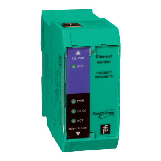
Page 9: Component Overview And Dimensions
Ethernet Isolator Product Specifications Non-Ex Non-Ex Non- Non- Intrinsically Intrinsically Intrinsically safe safe safe Ethernet Ethernet Ethernet Ethernet Switch Isolator Isolator Switch Ex d Enclosure Ethernet Ethernet Isolator Isolator Figure 2.1 Application Examples Component Overview and Dimensions Ethernet I.S. Port Isolator 10BASE-T/ 100BASE-TX... -
Page 10: Technical Data Ei-0D2-10Y-10B-Lt
Ethernet Isolator Product Specifications Technical Data EI-0D2-10Y-10B-LT Supply Rated voltage 19.2 ... 35 V DC Rated current 150 ... 100 mA Power loss Ethernet Interface Intrinsically safe port 10 BASE-T/100 BASE-TX Non-intrinsically safe port 10 BASE-T/100 BASE-TX Connection type 2 x RJ-45 , IEC 60603-7 Connector pinout female connector ;... -
Page 11: Mounting
2 devices with activated auto-crossover function. In general, the deactivation of the auto-crossover function at 1 device solves the problem. In certain cases, you have to switch-off auto-crossover at both sides. To prevent those connection problems, Pepperl+Fuchs recommends a fixed set- ting of the transfer polarity. Information on Signal Attenuation Because of derating effects at raising ambient temperatures, the maximum possi- ble Ethernet cable length may be reduced by 0.3 m .. - Page 12 Ethernet Isolator Installation and Commissioning Power Supply Wiring Connect the power supply to the Ethernet Isolator as follows. Remove the power supply connector plug from the bottom side of the Ethernet Isolator. Plug and screw the wires to the connector plug as follows: Plug-in the wired connector plug back into the power supply socket of the Ethernet Isolator.
-
Page 13: Suitable Ethernet Cables For Connection
Ethernet Isolator Installation and Commissioning Ethernet Wiring Plug in the standard, non-specific Ethernet cable into the non-intrinsically safe ports of the device. Interconnect the 2 Ethernet Isolators by plugging in an Ethernet cable into both the intrinsically safe ports of the devices. Ethernet Ethernet I.S. -
Page 14: Dismounting
Ethernet Isolator Installation and Commissioning Ethernet Cable Types for Different Use Cases Note Background Information The TIA/EIA-568-B Ethernet connector specification defines 2 types of pin assignment for an Ethernet cable. Standard Ethernet Patch Cable The standard Ethernet patch cable is a straight-through connection with both RJ45 connectors at each cable end wired the same way. -
Page 15: Operation
Ethernet Isolator Operation Operation LED Indication and Basic Troubleshooting LED Indication Explanation Remedy Ethernet Isolator active and powered Ethernet Isolator not pow- Check power supply and ered wiring Device defect Send the device to Pep- perl+Fuchs Ethernet Isolator active Ethernet transfer rate 10/100 10 Mbit/s Ethernet Isolator active... -
Page 16: Electromagnetic Compatibility Verification
Ethernet Isolator Electromagnetic Compatibility Verification Electromagnetic Compatibility Verification Verification in Accordance with EC Council Legislation Directive 2004/108/EC and 2014/30/EU Compatibility in Accordance with EN 61326-1 and NAMUR NE 21 Recommendation The electromagnetic compatibility (EMC) requirements, applicable for electrical equipment for measurement, control, and laboratory use in general are anchored in the international standard EN 61326. - Page 17 Pepperl+Fuchs Quality Download our latest policy here: www.pepperl-fuchs.com/quality www.pepperl-fuchs.com © Pepperl+Fuchs · Subject to modifications / TDOCT-1288C_ENG...
Need help?
Do you have a question about the EI-0D2-10Y-10B-LT and is the answer not in the manual?
Questions and answers